UNIT 2: LAN ARCHITECTURE, NETWORK PROTOCOLS AND MODELS
Key Unit Competency: To be able to identify computer network models, protocols and configure network devices
Introductory Activity
Look at figure 2.1 below and answer the following questions:

1. Describe what you see.
2. Are the above computers communicating? How and why?
3. In which case the communication may not be possible?
4. What type of network does the figure above represent?
5. How the Computers A and B are connected?
6. Is there any other way of connecting A, B and C
2.1 LAN architecture
Activity 2.1:
Visit your school computer lab and look at the existing Network and answer the followings questions:
1. Describe how computers are connected to the Network?
2. Determine the type of the logical or physical arrangement of network devices (nodes) in that network.
2.1.1 Definition of LAN Architecture?
A Local Area Network (LAN) architecture is the overall design of a computers network that interconnects computers within a limited area such as a residence, school, laboratory, university campus of office building. The LAN architecture consists of three levels: Physical, Media Access Control (MAC) and Logical Link Control (LLC).
•The LLC provides connection management, if needed.
•The Media Access Control (MAC) is a set of rules for accessing high speed physical links and for transferring data frames from one computer to another in a network.
•The Physical level deals mainly with actual transmission and reception of bits over the transmission medium.
2.1.2 Major Components of LANs
A LAN is made of the following main components:
-Hardware:
◊ Computers
◊ Network interface card (NIC) linked to physical address
◊ Media or Cables (Unshielded twisted pair, Coaxial cable, Optical fiber, Air for wireless)
◊ Hub, Switches, repeaters
-Access Methods: Rules that define how a computer puts data on and takes it from the network cable.
-Software: Programs to access and / or to manage the network.
2.1.3 Aspects of LAN architecture.
These aspects include:
-LAN’s physical topology: defines how the nodes of the network are physically connected
-LAN’s logical topology: how data is transmitted between nodes
-LAN’s MAC protocol: used for the physical identification of different devices within the network
2.1.4 Ethernet
Ethernet is a family of computer networking technologies commonly used in local area networks, metropolitan area networks and wide area networks. Ethernet cable is one of the most popular forms of network cable used in wired networks. They connect devices together within a local area network like PCs, routers and switches. A standard Ethernet network can transmit data at a rate up to 10 Megabits per second (10 Mbps). Ethernet uses CSMA/CD (Carrier Sense multiple Access with Collision Detection)
2.1.5 Carrier Sense Multiple Access with Collision Detection (CSMA/CD)
In a LAN, computers transmit data to each other. Normally, there is order to follow so that two computers can not send data at the same time while they are using the same route. When it happens that two computers send messages at the same time, there is what we call data collision. Therefore, a data collision occurs when two or more computers send data at the same time. When this happens, each computer stops data transmission and waits to resend it when the cable is free. Carrier Sense Multiple Access with Collision Detection (CSMA/CD) is a set of rules determining how network devices respond to a collision.
How does the CSMA/CD work?
Consider the following picture:

On the figure above, host A is trying to communicate with host B. Host A “senses” the wire and decides to send data. But, in the same time, host D sends its data to host C and the collision occurs. The sending devices (host A and host D) detect the collision and resend the data after a random period of time.
When a collision occurs on an Ethernet LAN, the following happens:
•A jam signal informs all devices that a collision occurred.
A signal sent by a device on an Ethernet network to indicate that a collision has occurred on the network is called a jam signal.
•The collision invokes a random back off algorithm (a set of rules which controls when each computer resend the data in order to assure that no more collision will happen again).
•Each device on the Ethernet segment stops transmitting for a short time until the timers expire.
•All hosts have equal priority to transmit after the timers have expired.
Application activity 2.1:
1. Realize a physical topology using devices like router, switches, Hubs, Ethernet cables and 4 computers available in your school computer lab as indicated in Fig. 2.2.
2. Describe how does the CSMA/CD enable the communication over Ethernet?
2.2 Cable Ethernet Standards
Activity 2.2:
Look around your school computer lab and answer the following question:Observe and describe the communication media (different types of Cables) available there.
2.2.1 Definition of standard
Standards provide guidelines to manufacturers, vendors, government agencies, and other service providers in guaranteeing national and international interoperability of data and telecommunications technology and processes. With Ethernet technologies, different types of standards have been so far used in networks.
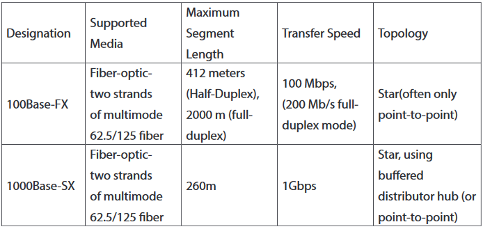
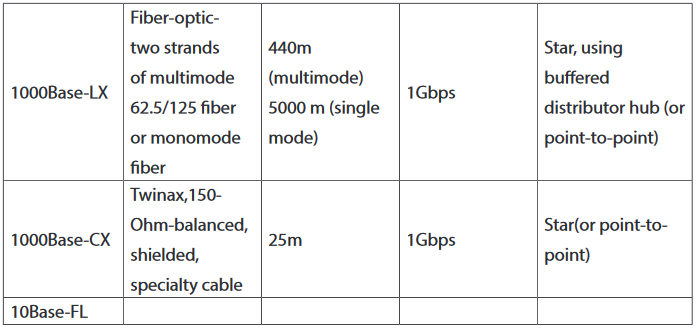
The different Ethernet technologies used in wired networks to connect computers are given in the following table. The choice of one or another type depends on the size of networks and the quantity of data to exchange.
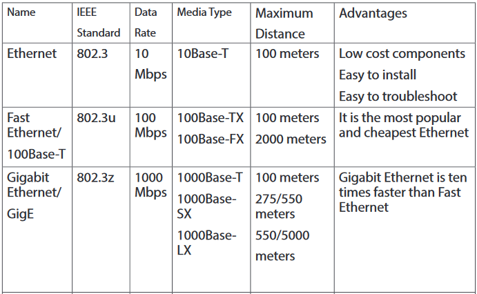
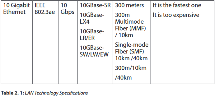
10BASE-F
10BASE-F is a generic term for the family of 10 Mbit/s Ethernet standards using fiber optic cable. In 10BASE-F, the 10 represents its maximum throughput of 10 Mbit/s, BASE indicates its use of base band transmission, and F indicates that it relies on medium of fiber-optic cable. In fact, there are at least three different kinds of 10BASE-F. All require two strands of 62.5/125 μm multimode fiber.One strand is used for data transmission and one strand is used for reception, making 10BASE-F a full-duplex technology.
The 10BASE-F variants include 10BASE-FL, 10BASE-FB and 10BASE-FP. Of these only 10BASE-FL experienced widespread use. All 10BASE-F variants deliver 10 Mbit/s over a fiber pair. These 10 Mbit/s standards have been largely replaced by faster Fast Ethernet, Gigabit Ethernet and 100 Gigabit Ethernet standards.
10BASE-FL
10BASE-FL is the most commonly used 10BASE-F specification of Ethernet over optical fiber. In 10BASE-FL, FL stands for fiber optic link. It replaces the original fiber-optic inter-repeater link (FOIRL) specification, but retains compatibility with FOIRL-based equipment. The maximum segment length supported is 2000 meters.When mixed with FOIRL equipment, maximum segment length is limited to FOIRL's 1000 meters.
Today, 10BASE-FL is rarely used in networking and has been replaced by the family of Fast Ethernet, Gigabit Ethernet and 100 Gigabit Ethernet standards.
10BASE-FB
The 10BASE-FB (10BASE-FiberBackbone) is a network segment used to bridge Ethernet hubs. Due to the synchronous operation of 10BASE-FB, delays normally associated with Ethernet repeaters are reduced, thus allowing segment distances to be extended without compromising the collision detection mechanism. The maximum allowable segment length for 10BASE-FB is 2000 meters.
10BASE-FP
10BASE-FP calls for a non-powered signal coupler capable of linking up to 33 devices, with each segment being up to 500m in length. This formed a star-type network centered on the signal coupler. There are no devices known to have implemented this standard.
2.2.1 Wireless network standards
Wireless LANs (WLANs) use radio frequencies (RFs) that are radiated into the air from an antenna that creates radio waves.
Because WLANs transmit over radio frequencies, they are regulated by the same types of laws used to govern things like AM/FM radios. It is the Federal Communications Commission (FCC) that regulates the use of wireless LAN devices, and the IEEE takes it from there and creates standards based on what frequencies the FCC releases for public use.
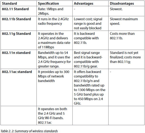
The wireless standards like the Ethernet standards are applied in different situations. The table below clearly describes each type.
2.2.3 Range, bandwidth and frequency
One characteristic that measures network performance is bandwidth. The bandwidth reflects the range of frequencies we need. However, the term can be used in two different contexts with two different measuring values: bandwidth in hertz and bandwidth in bits per second.
a. Bandwidth in Hertz
Bandwidth in hertz is the range of frequencies contained in a composite signal or the range of frequencies a channel can pass. For example, we can say the bandwidth of a subscriber telephone line is 4 kHz.
b.Bandwidth in Bits per Seconds
The term bandwidth can also refer to the number of bits per second that a channel, a link, or even a network can transmit per second. For example, one can say the bandwidth of a Fast Ethernet network is a maximum of 100 Mbps. This means that this network can send 100 Megabits per second.
2.2.3.1 Frequency and Network Range
The higher the frequency of a wireless signal, the shorter its range. 2.4 GHz wireless networks therefore cover a significantly larger range than 5 GHz networks. In particular, signals of 5 GHz frequencies do not penetrate solid objects nearly as well as do 2.4 GHz signals, limiting their reach inside homes.
Many older Wi-Fi devices do not contain 5 GHz radios and so must be connected to 2.4 GHz channels in any case.
2.2.3.2 Range, Bandwidth and Frequency
•The term ‘Bandwidth’ refers to the speed at which data is transferred over the wireless network (more bandwidth means faster downloading and uploading)
•The term ‘Range’ refers to the maximum distance from the router at which the network can be received (the greater the range, the further you can be from the router and still be connected).
•The term ‘Frequency’ refers to the number of waves that pass a fixed place in a given amount of time. So if the time it takes for a wave to pass is is 1/2 second, the frequency is 2 per second. If it takes 1/100 of an hour, the frequency is 100 per hour.
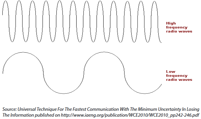
Usually frequency is measured in the hertz unit, named in honor of the 19th-century German physicist Heinrich Rudolf Hertz. The hertz measurement, abbreviated Hz, is the number of waves that pass by per second. For example, an "A" note on a violin string vibrates at about 440 Hz (440 vibrations per second).
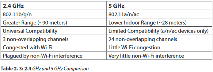
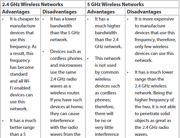
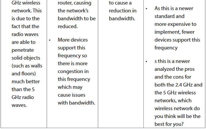
2.2.3.3 Advantages and Disadvantages of the 2.4 GHz and the 5 GHz Wireless Networks
2.2.3.4 Token ring
Token ring or IEEE 802.5 is a network where all computers are connected in a circular fashion. The term token is used to describe a segment of information that is sent through that circle. When a computer on the network can decode that token, it receives data.
A Multistation Access Unit (MSAU) is a hub or concentrator that connects a group of computers ("nodes" in network terminology) to a token ring local area network. For example, eight computers might be connected to an MSAU in one office and that MSAU would be connected to an MSAU in another office that served eight other computers. In turn, that MSAU could be connected to another MSAU in another office, which would be connected back to the first MSAU. Such a physical configuration is called a star topology. However, the logical configuration is a ring topology because every message passes through every computer one at a time, each passing it on to the next in a continuing circle.

Application activity 2.2:
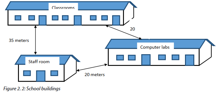
Your school has classrooms, computer labs and the staff room located in three different buildings as indicated in the figure below:
Questions:
1. Which kind of technology can you propose to connect computers in the 3 buildings. Explain you choice.
2. If you choose to install a wireless network within this school, in which building would you place the wireless device which serves the whole school? Explain.
3. What type of Ethernet cable would you use if you are requested to interconnect those three buildings? Explain.
2.3 Fiber Distributed Data Interface (FDDI)
2.3.1 Definition
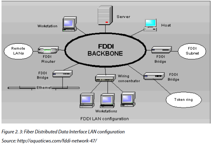
The Fiber Distributed Data Interface (FDDI) is a standard developed by the American National Standards Institute (ANSI) for transmitting data on optical fiber cables. FDDI supports transmission rates of 100 megabits per second on token-passing networks.
FDDI provides high-speed network backbones that can be used to connect and extend LANs.
2.3.2 Advantages of FDDI
The Fiber Distributed Data Interface allows the transmission of very large volumes of data over large distances. It provides high bandwidth.
2.3.3 Disadvantages
The Fiber Distributed Data Interface (FDDI) is an expensive technology to set up because the network devices require a special network card and also the required fiber optic cabling is expensive than twisted-pair cable. Because most Fiber Distributed Data Interface (FDDI) installations use a redundant second ring, more cabling is required.
2.3.4 Fiber Optic cables
A fiber optic cable is a glass or plastic strand that transmits information using light and is made up of one or more optical fibers enclosed together in a sheath or jacket. It has the following properties:
•Not affected by electromagnetic or radio frequency interference.
•All signals are converted to light pulses to enter the cable, and converted back into electrical signals when they leave it.
•Signals are clearer, can go farther, and have greater bandwidth than with copper cable.
•Signal can travel several miles or kilometers before the signal needs to be regenerated.
•Usually more expensive to use than copper cabling and the connectors are more costly and harder to assemble.
•Common connectors for fiber-optic networks are SC, ST, and LC. These three types of fiber optic connectors are half-duplex, which allows data to flow in only one direction.
Therefore, two cables are needed.
a. Types of fiber optic
There are three types of fiber optic cable commonly used: single mode, multimode and plastic optical fiber (POF).
1. Single-mode: Cable that has a very thin core. It is harder to make, uses lasers as a light source, and can transmit signals dozens of kilometers with ease.

2. Multimode: Cable that has a thicker core than single-mode cable. It is easier to make, can use simpler light sources (LEDs), and works well over distances of a few kilometers or less.

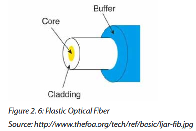
3. Plastic optical fiber (POF):Transparent glass or plastic fibers which allow light to be guided from one end to the other with minimal loss.
The Fiber optic technologies are summarized in the following table.
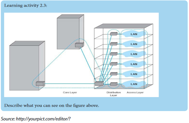
Application activity 2.3:
4. Discuss the advantages and disadvantages of FDDI within a Local Area Network.
5. Referring to the figure on learning activity 2.3, what type of fiber optic cable would you recommend for the core and distribution layers? Explain.
2.4 Network devices
Activity 2.4.
In groups, look at the devices given below and answer the questions:
6. Describe the role of each one within a Local Area Network.
7. Explain how you can make a Local Area Network using the following devices?
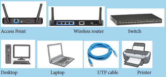
There are many networking devices: NIC cards, Repeaters, HUB, Bridges, Switches and Router
2.4.1 Wireless LAN cards (Network adapters)
Also called Network Interface Cards (NICs), they are connectivity devices enabling a desktop, server, printer, or other node to receive and transmit data over the network media
a. Types of Wireless Network Interface Cards (NICs)
NICs come in a variety of types depending on:
-The access method (for example, Ethernet versus Token Ring)
-Network transmission speed (for example, 100 Mbps versus 1 Gbps)
-Connector interfaces (for example, RJ-45 versus SC)
-Type of compatible motherboard or device (for example, PCI)
-Manufacturer (popular NIC manufacturers include 3Com, Adaptec, D
-Link, IBM, Intel,
-Kingston, Linksys, and so on)
b.Wireless NIC card installation and configuration
-Refer to the card manufacturer's quick
-start guide. Alternatively, you can also run the software installation program on the CD which comes with the PCI card and observe the steps to install it.
-Shut down the PC.
-Remove the cover.
-Locate an available PCI slot and remove the corresponding slot cover from the back of the PC.
-Carefully route the antenna through the open slot in the back of the PC, insert the card in the slot, and secure it. Replace the cover.
-Power up the PC. It should recognize and enable the new hardware.
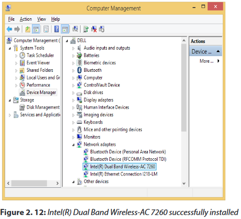
c. Wireless NIC card Driver installation through the Device Manager
Step 1: Right-click on Computer (or PC) to select Manage.
Step 2: On the left, select Device Manager to bring it up on the right.

Step 3: Right click on the unknown adapter to Update Driver Software.
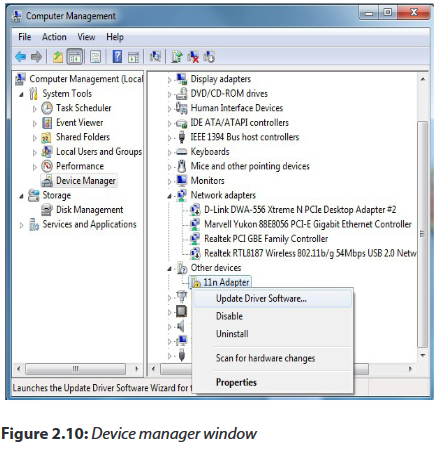
Step 4: Click to Search automatically for updated driver software.
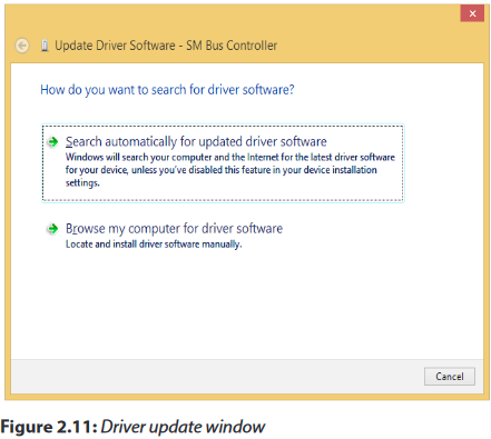
Step 5: Wait until the download process is successfully completed.
Step 6: Click on Save Settings or OK to apply the change.Confirmation of a successful Driver installation is achieved when the model of your adapter is labeled and listed in the Network adapters group of the Device Manager.
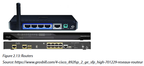
2.4.2 Routers and Access points
A wireless router is a device that performs the functions of a router and also includes the functions of a wireless access point. It is used to provide access to the Internet or a private computer network. Routers operate at the Network layer (Layer 3) of the OSI Model.
The Wireless access points (APs or WAPs) are networking devices that allow wireless Wi-Fi devices to connect to a wired network.
2.4.3 Configuring a wireless router
Step 1: Get to know your wireless router
•A power input jack one.
•One or more wired Ethernet jacks (often labeled 1, 2, 3, 4) for computers on your network which don't have wireless ability.
•One Ethernet jack for your broadband connection, often labeled “WAN” or “Internet.”
•A reset button. to
Step 2: Connect your router a wired PC for initial setup
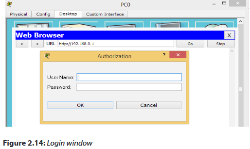
Step 3: Open web browser and connect to wireless router administration INTERFACE
To connect to your router, you need to know its default IP address and connect your browser to http://routeripaddress. For example, if you own a Linksys brand wireless router, its default IP address is 192.168.1.1, and therefore you open your browser to the URL http://192.168.1.1.
Most wireless routers also require you to log in to access configuration pages. Your router includes a manual or a "quick setup" guide which details both its default IP address and default login.
Step 4: Determine your broadband type
There are three common broadband connection methods:
•DHCP Dynamic IP: Basic network parameters are automatically assigned to your router by the broadband modem.
•PPPoE: Requires you to supply a username and password provided to you by your ISP.
•Static IP: Your broadband provider would have supplied you with a set of numeric addresses you need to connect to the network, as they are not assigned automatically.
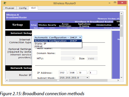
Step 5: Configure your broadband connection
On this model, you clicked the "Setup" menu and "Basic setup" sub menu. Again, your model may differ, and newer models may include a guided wizard that takes you through these steps.
Step 6: Configure your wireless network basics
If your router is connected to broadband and it is working successfully, we can setup the wireless networking configuration. On our sample router we clicked the "Wireless" sub menu.
Assign your wireless network a name, also known as Service Set Identifier (SSID). Choose a unique name in case there may be neighboring wireless routers nearby.

Step 7: Configure your wireless security
Most wireless network users will select one of four degrees of encryption security available in wireless hardware today.
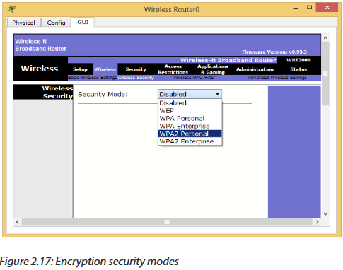
1. WEP: The oldest and least secure data encryption. All wireless gear supports WEP, though, it is useful when you need at least some kind of encryption to be compatible with older wireless hardware.
2. WPA: A more secure upgrade to WEP. Designed so that many older devices which included only WEP can be upgraded to support WPA.
3. WPA2: A significantly more secure upgrade to either WEP or WPA. Cannot upgrade older hardware to WPA2, but many new wireless devices support WPA2.
Note: At each step you must click on the “save Settings” button before you proceed with the next step
2.4.3.1 Router Operation Mode
Many of the routers offers different operation modes that you can use.
a. Wireless Router Mode
In wireless router/ IP sharing mode, the router connects to the Internet via PPPoE, DHCP, PPTP, L2TP, or Static IP and shares the wireless network to LAN clients or devices. Select this mode if you are a first-time user or you are not currently using any wired/wireless routers.
b.Repeater Mode
In Repeater mode, your router wirelessly connects to an existing wireless network to extend the wireless coverage. You will generally use repeaters or wireless extenders
when you have hard to reach places with your home Wi-Fi setup.
c. Access Point (AP) Mode
In Access Point (AP) mode, the router connects to a wireless router through an Ethernet cable to extend the wireless signal coverage to other network clients. This mode is best to be used in an office, hotel, and places where you only have wired network.
d.Media Bridge or Client Mode
With client mode or media bridge, it can connect to a wired device and works as a wireless adapter to receive wireless signal from your wireless network. The reason for this mode is that it can increase the speed of your wireless connection so that it matches the speed of the Ethernet connection.
2.4.3.2 Default gateway
A default gateway is used to allow devices in one network to communicate with devices in another network. If your computer, for example, is requesting an Internet webpage, the request first runs through your default gateway before exiting the local network to reach the Internet.An easier way to understand a default gateway might be to think of it as an intermediate device between the local network and the Internet.
a. Configuring the default gateway on a wireless router
Start packet tracer, add a wireless router and do the following:
-Click on wireless router and go to GUI tab.
-Set the Internet Connection type to Static IP.
-Configure the IP addressing according to the figure below.
-Scroll down and click on Save Settings.

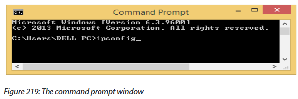
b.How to find your default gateway IP address
You might need to know the IP address of the default gateway if there is a network problem or if you need to make changes to your router.
-In Microsoft Windows, the IP address of a computer's default gateway can be accessed through Command Prompt with the ipconfig command, as well as through the Control Panel.
-The netstat and ip route commands are used on macOS and Linux for finding the default gateway address.

c. Configuring a default gateway on a desktop
-Open the control panel-Click on Network and Internet
-Click on Network and sharing center
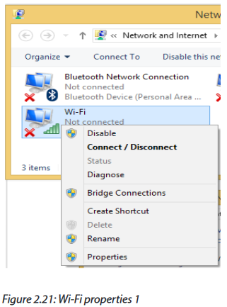
-Click on adapter settings
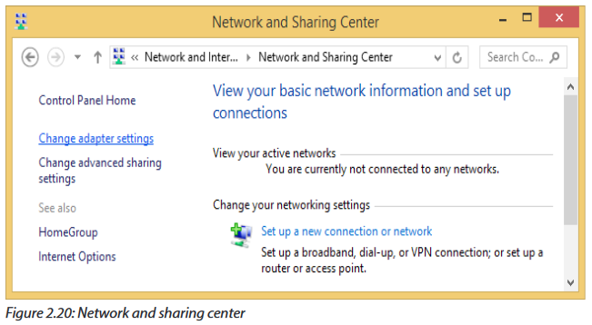
-Right click on wi-fi and choose properties

Key Unit Competency: To be able to identify computer network models, protocols and configure network devices
Introductory Activity
Look at figure 2.1 below and answer the following questions:
1. Describe what you see.
2. Are the above computers communicating? How and why?
3. In which case the communication may not be possible?
4. What type of network does the figure above represent?
5. How the Computers A and B are connected?
6. Is there any other way of connecting A, B and C
2.1 LAN architecture
Activity 2.1:
Visit your school computer lab and look at the existing Network and answer the followings questions:
1. Describe how computers are connected to the Network?
2. Determine the type of the logical or physical arrangement of network devices (nodes) in that network.
2.1.1 Definition of LAN Architecture?
A Local Area Network (LAN) architecture is the overall design of a computers network that interconnects computers within a limited area such as a residence, school, laboratory, university campus of office building. The LAN architecture consists of three levels: Physical, Media Access Control (MAC) and Logical Link Control (LLC).
•The LLC provides connection management, if needed.
•The Media Access Control (MAC) is a set of rules for accessing high speed physical links and for transferring data frames from one computer to another in a network.
•The Physical level deals mainly with actual transmission and reception of bits over the transmission medium.
2.1.2 Major Components of LANs
A LAN is made of the following main components:
-Hardware:
◊ Computers
◊ Network interface card (NIC) linked to physical address
◊ Media or Cables (Unshielded twisted pair, Coaxial cable, Optical fiber, Air for wireless)
◊ Hub, Switches, repeaters
-Access Methods: Rules that define how a computer puts data on and takes it from the network cable.
-Software: Programs to access and / or to manage the network.
2.1.3 Aspects of LAN architecture.
These aspects include:
-LAN’s physical topology: defines how the nodes of the network are physically connected
-LAN’s logical topology: how data is transmitted between nodes
-LAN’s MAC protocol: used for the physical identification of different devices within the network
2.1.4 Ethernet
Ethernet is a family of computer networking technologies commonly used in local area networks, metropolitan area networks and wide area networks. Ethernet cable is one of the most popular forms of network cable used in wired networks. They connect devices together within a local area network like PCs, routers and switches. A standard Ethernet network can transmit data at a rate up to 10 Megabits per second (10 Mbps). Ethernet uses CSMA/CD (Carrier Sense multiple Access with Collision Detection)
2.1.5 Carrier Sense Multiple Access with Collision Detection (CSMA/CD)
In a LAN, computers transmit data to each other. Normally, there is order to follow so that two computers can not send data at the same time while they are using the same route. When it happens that two computers send messages at the same time, there is what we call data collision. Therefore, a data collision occurs when two or more computers send data at the same time. When this happens, each computer stops data transmission and waits to resend it when the cable is free. Carrier Sense Multiple Access with Collision Detection (CSMA/CD) is a set of rules determining how network devices respond to a collision.
How does the CSMA/CD work?
Consider the following picture:
On the figure above, host A is trying to communicate with host B. Host A “senses” the wire and decides to send data. But, in the same time, host D sends its data to host C and the collision occurs. The sending devices (host A and host D) detect the collision and resend the data after a random period of time.
When a collision occurs on an Ethernet LAN, the following happens:
•A jam signal informs all devices that a collision occurred.
A signal sent by a device on an Ethernet network to indicate that a collision has occurred on the network is called a jam signal.
•The collision invokes a random back off algorithm (a set of rules which controls when each computer resend the data in order to assure that no more collision will happen again).
•Each device on the Ethernet segment stops transmitting for a short time until the timers expire.
•All hosts have equal priority to transmit after the timers have expired.
Application activity 2.1:
1. Realize a physical topology using devices like router, switches, Hubs, Ethernet cables and 4 computers available in your school computer lab as indicated in Fig. 2.2.
2. Describe how does the CSMA/CD enable the communication over Ethernet?
2.2 Cable Ethernet Standards
Activity 2.2:
Look around your school computer lab and answer the following question:Observe and describe the communication media (different types of Cables) available there.
2.2.1 Definition of standard
Standards provide guidelines to manufacturers, vendors, government agencies, and other service providers in guaranteeing national and international interoperability of data and telecommunications technology and processes. With Ethernet technologies, different types of standards have been so far used in networks.
The different Ethernet technologies used in wired networks to connect computers are given in the following table. The choice of one or another type depends on the size of networks and the quantity of data to exchange.
10BASE-F
10BASE-F is a generic term for the family of 10 Mbit/s Ethernet standards using fiber optic cable. In 10BASE-F, the 10 represents its maximum throughput of 10 Mbit/s, BASE indicates its use of base band transmission, and F indicates that it relies on medium of fiber-optic cable. In fact, there are at least three different kinds of 10BASE-F. All require two strands of 62.5/125 μm multimode fiber.One strand is used for data transmission and one strand is used for reception, making 10BASE-F a full-duplex technology.
The 10BASE-F variants include 10BASE-FL, 10BASE-FB and 10BASE-FP. Of these only 10BASE-FL experienced widespread use. All 10BASE-F variants deliver 10 Mbit/s over a fiber pair. These 10 Mbit/s standards have been largely replaced by faster Fast Ethernet, Gigabit Ethernet and 100 Gigabit Ethernet standards.
10BASE-FL
10BASE-FL is the most commonly used 10BASE-F specification of Ethernet over optical fiber. In 10BASE-FL, FL stands for fiber optic link. It replaces the original fiber-optic inter-repeater link (FOIRL) specification, but retains compatibility with FOIRL-based equipment. The maximum segment length supported is 2000 meters.When mixed with FOIRL equipment, maximum segment length is limited to FOIRL's 1000 meters.
Today, 10BASE-FL is rarely used in networking and has been replaced by the family of Fast Ethernet, Gigabit Ethernet and 100 Gigabit Ethernet standards.
10BASE-FB
The 10BASE-FB (10BASE-FiberBackbone) is a network segment used to bridge Ethernet hubs. Due to the synchronous operation of 10BASE-FB, delays normally associated with Ethernet repeaters are reduced, thus allowing segment distances to be extended without compromising the collision detection mechanism. The maximum allowable segment length for 10BASE-FB is 2000 meters.
10BASE-FP
10BASE-FP calls for a non-powered signal coupler capable of linking up to 33 devices, with each segment being up to 500m in length. This formed a star-type network centered on the signal coupler. There are no devices known to have implemented this standard.
2.2.1 Wireless network standards
Wireless LANs (WLANs) use radio frequencies (RFs) that are radiated into the air from an antenna that creates radio waves.
Because WLANs transmit over radio frequencies, they are regulated by the same types of laws used to govern things like AM/FM radios. It is the Federal Communications Commission (FCC) that regulates the use of wireless LAN devices, and the IEEE takes it from there and creates standards based on what frequencies the FCC releases for public use.
The wireless standards like the Ethernet standards are applied in different situations. The table below clearly describes each type.
2.2.3 Range, bandwidth and frequency
One characteristic that measures network performance is bandwidth. The bandwidth reflects the range of frequencies we need. However, the term can be used in two different contexts with two different measuring values: bandwidth in hertz and bandwidth in bits per second.
a. Bandwidth in Hertz
Bandwidth in hertz is the range of frequencies contained in a composite signal or the range of frequencies a channel can pass. For example, we can say the bandwidth of a subscriber telephone line is 4 kHz.
b.Bandwidth in Bits per Seconds
The term bandwidth can also refer to the number of bits per second that a channel, a link, or even a network can transmit per second. For example, one can say the bandwidth of a Fast Ethernet network is a maximum of 100 Mbps. This means that this network can send 100 Megabits per second.
2.2.3.1 Frequency and Network Range
The higher the frequency of a wireless signal, the shorter its range. 2.4 GHz wireless networks therefore cover a significantly larger range than 5 GHz networks. In particular, signals of 5 GHz frequencies do not penetrate solid objects nearly as well as do 2.4 GHz signals, limiting their reach inside homes.
Many older Wi-Fi devices do not contain 5 GHz radios and so must be connected to 2.4 GHz channels in any case.
2.2.3.2 Range, Bandwidth and Frequency
•The term ‘Bandwidth’ refers to the speed at which data is transferred over the wireless network (more bandwidth means faster downloading and uploading)
•The term ‘Range’ refers to the maximum distance from the router at which the network can be received (the greater the range, the further you can be from the router and still be connected).
•The term ‘Frequency’ refers to the number of waves that pass a fixed place in a given amount of time. So if the time it takes for a wave to pass is is 1/2 second, the frequency is 2 per second. If it takes 1/100 of an hour, the frequency is 100 per hour.
Usually frequency is measured in the hertz unit, named in honor of the 19th-century German physicist Heinrich Rudolf Hertz. The hertz measurement, abbreviated Hz, is the number of waves that pass by per second. For example, an "A" note on a violin string vibrates at about 440 Hz (440 vibrations per second).
2.2.3.3 Advantages and Disadvantages of the 2.4 GHz and the 5 GHz Wireless Networks
2.2.3.4 Token ring
Token ring or IEEE 802.5 is a network where all computers are connected in a circular fashion. The term token is used to describe a segment of information that is sent through that circle. When a computer on the network can decode that token, it receives data.
A Multistation Access Unit (MSAU) is a hub or concentrator that connects a group of computers ("nodes" in network terminology) to a token ring local area network. For example, eight computers might be connected to an MSAU in one office and that MSAU would be connected to an MSAU in another office that served eight other computers. In turn, that MSAU could be connected to another MSAU in another office, which would be connected back to the first MSAU. Such a physical configuration is called a star topology. However, the logical configuration is a ring topology because every message passes through every computer one at a time, each passing it on to the next in a continuing circle.
Application activity 2.2:
Your school has classrooms, computer labs and the staff room located in three different buildings as indicated in the figure below:
Questions:
1. Which kind of technology can you propose to connect computers in the 3 buildings. Explain you choice.
2. If you choose to install a wireless network within this school, in which building would you place the wireless device which serves the whole school? Explain.
3. What type of Ethernet cable would you use if you are requested to interconnect those three buildings? Explain.
2.3 Fiber Distributed Data Interface (FDDI)
2.3.1 Definition
The Fiber Distributed Data Interface (FDDI) is a standard developed by the American National Standards Institute (ANSI) for transmitting data on optical fiber cables. FDDI supports transmission rates of 100 megabits per second on token-passing networks.
FDDI provides high-speed network backbones that can be used to connect and extend LANs.
2.3.2 Advantages of FDDI
The Fiber Distributed Data Interface allows the transmission of very large volumes of data over large distances. It provides high bandwidth.
2.3.3 Disadvantages
The Fiber Distributed Data Interface (FDDI) is an expensive technology to set up because the network devices require a special network card and also the required fiber optic cabling is expensive than twisted-pair cable. Because most Fiber Distributed Data Interface (FDDI) installations use a redundant second ring, more cabling is required.
2.3.4 Fiber Optic cables
A fiber optic cable is a glass or plastic strand that transmits information using light and is made up of one or more optical fibers enclosed together in a sheath or jacket. It has the following properties:
•Not affected by electromagnetic or radio frequency interference.
•All signals are converted to light pulses to enter the cable, and converted back into electrical signals when they leave it.
•Signals are clearer, can go farther, and have greater bandwidth than with copper cable.
•Signal can travel several miles or kilometers before the signal needs to be regenerated.
•Usually more expensive to use than copper cabling and the connectors are more costly and harder to assemble.
•Common connectors for fiber-optic networks are SC, ST, and LC. These three types of fiber optic connectors are half-duplex, which allows data to flow in only one direction.
Therefore, two cables are needed.
a. Types of fiber optic
There are three types of fiber optic cable commonly used: single mode, multimode and plastic optical fiber (POF).
1. Single-mode: Cable that has a very thin core. It is harder to make, uses lasers as a light source, and can transmit signals dozens of kilometers with ease.
2. Multimode: Cable that has a thicker core than single-mode cable. It is easier to make, can use simpler light sources (LEDs), and works well over distances of a few kilometers or less.
3. Plastic optical fiber (POF):Transparent glass or plastic fibers which allow light to be guided from one end to the other with minimal loss.
The Fiber optic technologies are summarized in the following table.
Application activity 2.3:
4. Discuss the advantages and disadvantages of FDDI within a Local Area Network.
5. Referring to the figure on learning activity 2.3, what type of fiber optic cable would you recommend for the core and distribution layers? Explain.
2.4 Network devices
Activity 2.4.
In groups, look at the devices given below and answer the questions:
6. Describe the role of each one within a Local Area Network.
7. Explain how you can make a Local Area Network using the following devices?
There are many networking devices: NIC cards, Repeaters, HUB, Bridges, Switches and Router
2.4.1 Wireless LAN cards (Network adapters)
Also called Network Interface Cards (NICs), they are connectivity devices enabling a desktop, server, printer, or other node to receive and transmit data over the network media
a. Types of Wireless Network Interface Cards (NICs)
NICs come in a variety of types depending on:
-The access method (for example, Ethernet versus Token Ring)
-Network transmission speed (for example, 100 Mbps versus 1 Gbps)
-Connector interfaces (for example, RJ-45 versus SC)
-Type of compatible motherboard or device (for example, PCI)
-Manufacturer (popular NIC manufacturers include 3Com, Adaptec, D
-Link, IBM, Intel,
-Kingston, Linksys, and so on)
b.Wireless NIC card installation and configuration
-Refer to the card manufacturer's quick
-start guide. Alternatively, you can also run the software installation program on the CD which comes with the PCI card and observe the steps to install it.
-Shut down the PC.
-Remove the cover.
-Locate an available PCI slot and remove the corresponding slot cover from the back of the PC.
-Carefully route the antenna through the open slot in the back of the PC, insert the card in the slot, and secure it. Replace the cover.
-Power up the PC. It should recognize and enable the new hardware.
c. Wireless NIC card Driver installation through the Device Manager
Step 1: Right-click on Computer (or PC) to select Manage.
Step 2: On the left, select Device Manager to bring it up on the right.
Step 3: Right click on the unknown adapter to Update Driver Software.
Step 4: Click to Search automatically for updated driver software.
Step 5: Wait until the download process is successfully completed.
Step 6: Click on Save Settings or OK to apply the change.Confirmation of a successful Driver installation is achieved when the model of your adapter is labeled and listed in the Network adapters group of the Device Manager.
2.4.2 Routers and Access points
A wireless router is a device that performs the functions of a router and also includes the functions of a wireless access point. It is used to provide access to the Internet or a private computer network. Routers operate at the Network layer (Layer 3) of the OSI Model.
The Wireless access points (APs or WAPs) are networking devices that allow wireless Wi-Fi devices to connect to a wired network.
2.4.3 Configuring a wireless router
Step 1: Get to know your wireless router
•A power input jack one.
•One or more wired Ethernet jacks (often labeled 1, 2, 3, 4) for computers on your network which don't have wireless ability.
•One Ethernet jack for your broadband connection, often labeled “WAN” or “Internet.”
•A reset button. to
Step 2: Connect your router a wired PC for initial setup
Step 3: Open web browser and connect to wireless router administration INTERFACE
To connect to your router, you need to know its default IP address and connect your browser to http://routeripaddress. For example, if you own a Linksys brand wireless router, its default IP address is 192.168.1.1, and therefore you open your browser to the URL http://192.168.1.1.
Most wireless routers also require you to log in to access configuration pages. Your router includes a manual or a "quick setup" guide which details both its default IP address and default login.
Step 4: Determine your broadband type
There are three common broadband connection methods:
•DHCP Dynamic IP: Basic network parameters are automatically assigned to your router by the broadband modem.
•PPPoE: Requires you to supply a username and password provided to you by your ISP.
•Static IP: Your broadband provider would have supplied you with a set of numeric addresses you need to connect to the network, as they are not assigned automatically.
Step 5: Configure your broadband connection
On this model, you clicked the "Setup" menu and "Basic setup" sub menu. Again, your model may differ, and newer models may include a guided wizard that takes you through these steps.
Step 6: Configure your wireless network basics
If your router is connected to broadband and it is working successfully, we can setup the wireless networking configuration. On our sample router we clicked the "Wireless" sub menu.
Assign your wireless network a name, also known as Service Set Identifier (SSID). Choose a unique name in case there may be neighboring wireless routers nearby.
Step 7: Configure your wireless security
Most wireless network users will select one of four degrees of encryption security available in wireless hardware today.
1. WEP: The oldest and least secure data encryption. All wireless gear supports WEP, though, it is useful when you need at least some kind of encryption to be compatible with older wireless hardware.
2. WPA: A more secure upgrade to WEP. Designed so that many older devices which included only WEP can be upgraded to support WPA.
3. WPA2: A significantly more secure upgrade to either WEP or WPA. Cannot upgrade older hardware to WPA2, but many new wireless devices support WPA2.
Note: At each step you must click on the “save Settings” button before you proceed with the next step
2.4.3.1 Router Operation Mode
Many of the routers offers different operation modes that you can use.
a. Wireless Router Mode
In wireless router/ IP sharing mode, the router connects to the Internet via PPPoE, DHCP, PPTP, L2TP, or Static IP and shares the wireless network to LAN clients or devices. Select this mode if you are a first-time user or you are not currently using any wired/wireless routers.
b.Repeater Mode
In Repeater mode, your router wirelessly connects to an existing wireless network to extend the wireless coverage. You will generally use repeaters or wireless extenders
when you have hard to reach places with your home Wi-Fi setup.
c. Access Point (AP) Mode
In Access Point (AP) mode, the router connects to a wireless router through an Ethernet cable to extend the wireless signal coverage to other network clients. This mode is best to be used in an office, hotel, and places where you only have wired network.
d.Media Bridge or Client Mode
With client mode or media bridge, it can connect to a wired device and works as a wireless adapter to receive wireless signal from your wireless network. The reason for this mode is that it can increase the speed of your wireless connection so that it matches the speed of the Ethernet connection.
2.4.3.2 Default gateway
A default gateway is used to allow devices in one network to communicate with devices in another network. If your computer, for example, is requesting an Internet webpage, the request first runs through your default gateway before exiting the local network to reach the Internet.An easier way to understand a default gateway might be to think of it as an intermediate device between the local network and the Internet.
a. Configuring the default gateway on a wireless router
Start packet tracer, add a wireless router and do the following:
-Click on wireless router and go to GUI tab.
-Set the Internet Connection type to Static IP.
-Configure the IP addressing according to the figure below.
-Scroll down and click on Save Settings.
b.How to find your default gateway IP address
You might need to know the IP address of the default gateway if there is a network problem or if you need to make changes to your router.
-In Microsoft Windows, the IP address of a computer's default gateway can be accessed through Command Prompt with the ipconfig command, as well as through the Control Panel.
-The netstat and ip route commands are used on macOS and Linux for finding the default gateway address.
c. Configuring a default gateway on a desktop
-Open the control panel-Click on Network and Internet
-Click on Network and sharing center
-Click on adapter settings
-Right click on wi-fi and choose properties
-Choose Internet Protocol Version 4 (TCP/IPv4) and click on properties

-Enter IP address as follows and then click on OK:

2.4.4 Public and private IP2.
4.4.1 Public IP addresses
A public IP address is the one that your ISP (Internet Service Provider) provides to identify your home network to the outside world. It is an IP address that is unique throughout the entire Internet. A public IP address is worldwide unique, and can only be assigned to a unique device
Depending on your service, you might have an IP address that never changes (a fixed or static IP address). But most ISPs provide an IP address that can change from time to time (a dynamic IP address)
Example: Web and email servers directly accessible from the Internet use public IP addresses.
2.4.4.2 Private IP addresses
A private IP address provides unique identification for devices that are within your Local Area Network, such as your computer, your smartphones, and so on.If every device on every network had to have real routable public IP addresses, we would have run out of IP addresses to hand out years ago. Private IP addresses are used for the following reasons:
-To create addresses that cannot be routed through the public Internet
-To conserve public addresses
Examples:
-Computers, tablets and smartphones within an organization are usually assigned private IP addresses.
-A network printer residing in your school computer lab is assigned a private address so that only users within computer lab can print to your local printer.
-Notice that IP addresses, public or private, are assigned to devices according to network classes. The most used classes are A, B and C. They differ according to the number of networks and hence to the number of IP addresses in one network. From A to C, the number of possible networks increase while number of available IP addresses in a network reduces.

2.4.5 Configuring a wireless Access Point
The physical setup for a wireless access point is pretty simple: you take it out of the box, put it on a shelf or on top of a bookcase near a network jack and a power outlet, plug in the power cable, and plug in the network cable.
To get to the configuration page for the access point, you need to know the access point’s IP address. Then, you just type that address into the address bar of a browser from any computer on the network.
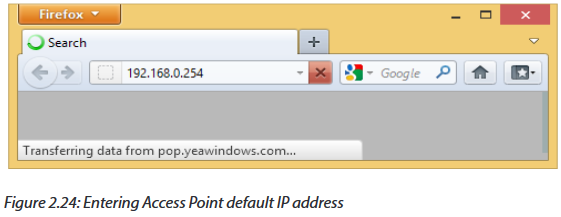
For example to configure TP-Link TL-WA701ND Access Point you will follow the following steps:
Step 1: Power the TP-Link TL-WA701ND using the barrel jack or PoE (Power-over-Ethernet) injector, and connect a computer to the access point using an Ethernet cable (if using the PoE injector, connect the LAN port to your computer, and the POE port to the access point).
Step 2: Ensure all wireless interfaces are disabled on the computer (such as WiFi and Bluetooth) and that DHCP is enabled on the Ethernet interface. Open a web browser and access the TL-WA701ND by entering 192.168.0.254 into the address bar.
Step 3: Log in using username admin and password admin
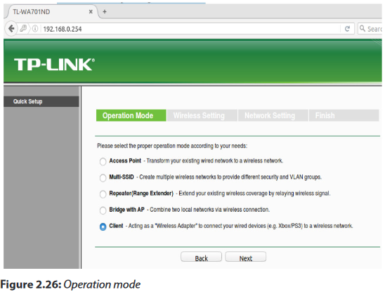
Step 4: The Quick Setup wizard will load in the browser. Click Next to start the configuration process.

Step 5: Select Client from the list of operating modes. Click Next.
Step 6: Click Survey to scan for a list of available wireless access points. Alternatively, skip to step 8 and manually enter information.

Step 7: From the list of available WiFi networks, select the network to use by clicking Connect to the far right. Make sure the network has a good connection by checking the signal strength. The higher the number, the stronger the connection.
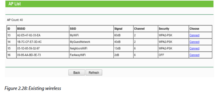
Step 8: Once the Connect option is clicked, these fields will automatically fill in. Alternatively, enter the Wireless Name (SSID) and Wireless Security Mode and Wireless Password. The wireless security settings will need to be manually entered for any password protected WiFi network. Click Next.

Step 9: The default values are typically fine for these settings. If needed, obtain the correct settings from the network administrator. Be sure to make a note/take a screenshot of the IP address set in this step, as it will replace the original fallback IP address. When the correct settings have been applied, click Next.
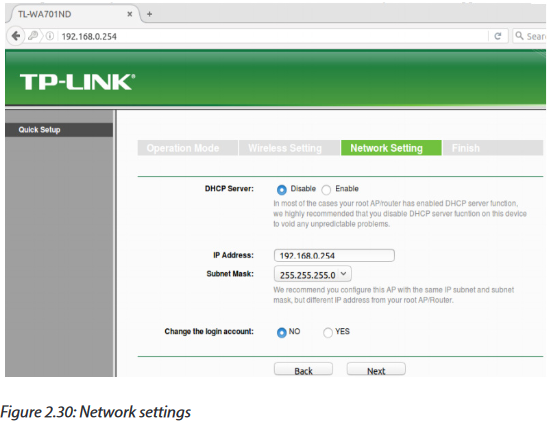
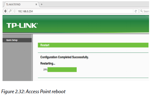
Step 10: Make a note or take a screenshot of the applied settings if desired, then click Save.

Step 11: The device will reboot. The configuration page will likely not load; try loading a web-page (e.g. http://www.irembo.gov.rw) while the TP-Link Access Point is connected to the computer to see if there is Internet connectivity.
Step 12: Troubleshooting
•The TP-Link TP-WA701ND does not have any LEDs illuminated
* Ensure the access point has power either directly to the barrel jack on the back, or via the POE injector’s POE Ethernet port. The POE injector requires power via barrel jack.
* Verify the ON/OFF button next to the access point’s Ethernet port is depressed in the ON position.
•I cannot access the device configuration page.
* The TP-Link WA701ND has a default fallback IP address of 192.168.0.254. To access the device configuration pages, connect a computer directly via an Ethernet cable, configure the computer to use an IPv4 address in the same range (for example, 192.168.0.100), open a web browser, and enter the fallback IP address of 192.168.0.254 in the address bar. If you changed the IP address on the Network Setting page during configuration step 9, use that IP address instead.
•I cannot access the device at all (lost credentials, major configuration issue, etc)
* The TP-Link TL-WA701ND has a recessed reset button located on the back of the device. This button is closest to the antenna, and a pin or paperclip is needed to press it. Hold the button down for 8+ seconds. All of the LEDs should turn off and back on; after this the initial configuration steps can be used to gain access. Note that this will reset all device settings to the factory default.
2.4.5 How to connect to the Internet through your wireless access point?
a. Connecting to Internet through the control panel
-Open the windows control panel, and then click network and Internet.
-The Network and Internet window appears.

-Click network and sharing center.
-The Network and Sharing Center window appears.
-Click set up a new connection or network.
 -Set up a Connection or Network window appears.-Click Manually connect to a wireless network
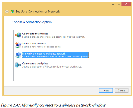
-Click Manually connect to a wireless network
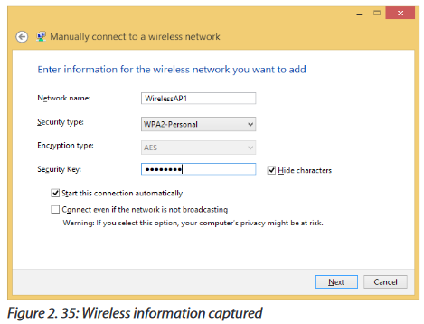
-Enter your wireless name in the Network name textbox, for example in our case we want to connect to “Wireless AP”
-Choose WPA2
-Personal for security type
-Choose AES for encryption type
-Type wireless key in the security key textbox
-Click next
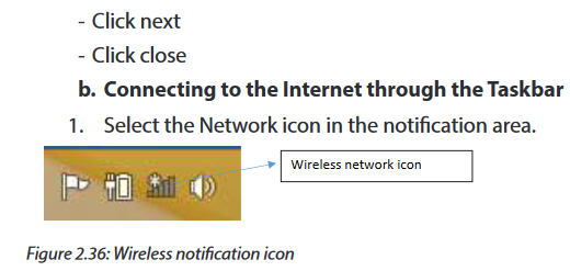
2. In the list of networks, choose the network that you want to connect to, and then select Connect.
3. Type the security key (often called the password).
4. Follow additional instructions if there are any.
2.4.7 Wireless Access Point vs Router
The Wireless Access Points (AP) and routers play the similar role but they have some differences. They all connect different networks. A router often has an Access Point built-in, but a standalone Access Point can’t be a router. An AP can be compared to a modem which is limited in its functionality on managing multiple devices or controlling an entire network with many devices.Routers on the other hand can manage an entire home or small business giving network capability to many computers and devices simultaneously.
2.4.7.1 Wireless Access Point Functions
APs give wireless network ability to any device that only has a hard-wired connection. It is done by plugging in an Ethernet cable and the AP would then communicate with WiFi devices and giving them network access. .For example a printer that has no built-in wireless can have a access point added which will give it wireless ability.
While current routers have built-in WiFi and play many roles including being an AP, many don’t use dedicated AP.APs are still used in many networks and they are used to help with WiFi dead spots and extending a wireless network.
An AP can be added in locations that have bad wireless network ability and give good coverage throughout a home or business.
2.4.7.2 Router Functions
From the above section, a router is a network device that can transfer data wirelessly or wired. It forwards data packets to the desired device and control LAN (local Area Networks) or WAN (Wide Area Networks) networks
2.4.7 SSID and encryption
2.4.7.1 SSID and Wireless Networking
An SSID (Service Set Identifier) is the primary name associated with an 802.11 Wireless Local Area Network (WLAN) including home networks and public hotspots. Client devices use this name to identify and join wireless networks.
When you right click on the icon of wireless network in the Task Bar (Bottom Right of the computer’s screen), the displayed list of names of different networks are the SSID that are covered now or have been used in past.
On home Wi-Fi networks, a broadband router or broadband modem stores the SSID but allows administrators to change it. Routers can broadcast this name to help wireless clients find the network. Router manufacturers set a default SSID for the Wi-Fi unit, such as Linksys, xfinitywifi, NETGEAR, dlink or just default. However, since the SSID can be changed, not all wireless networks have a standard name like that.
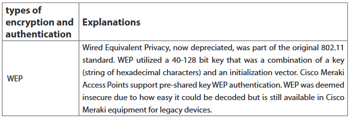
2.4.7.2 Wireless fundamentals: Encryption and authentication
Wireless encryption and authentication help users to make an educated decision on what type of security to implement into their wireless network. There exist different types of encryption and authentication. For example, CISCO Meraki is using the following:


Application activity 2.4:
A. Look around your school computer lab and do the following:
•Uninstall and reinstall wireless adapters into your desktops
•Switch on your computers and check whether wireless drivers are installed.
•Using your computers, check for available wireless signal?
•Login into your wireless router and change its SSID to “NetworkingLab”.
•What is the IP address of your computer?
•Discuss the advantages of protecting your wireless network with a password?
B. Using one smart phone, setup a computer network made of your laptops. Describe how to connect to that network. What is the name of the network? Change that name and set up a new password.
2.5 computer Network Protocols
Activity 2.5:
The school computer lab has 20 computers connected to the Local Area Network and Internet. Using his computer, the teacher wishes to get a copy of 40 MB document in all computers but he does not have any storage devices to facilitate the task. In groups, discuss possible ways to obtain this document in all computers in laboratory. Apply your proposed solutions.
2.5.1 Definition
A network protocol defines rules and conventions for communication between network devices. Network protocols include mechanisms for devices to identify and make connections with each other, as well as formatting rules that specify how data is packaged into messages sent and received.
Network protocols are grouped such that each one relies on the protocols that underlie it sometimes referred to as a protocol stack. The key network protocols are the following:
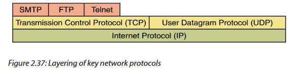
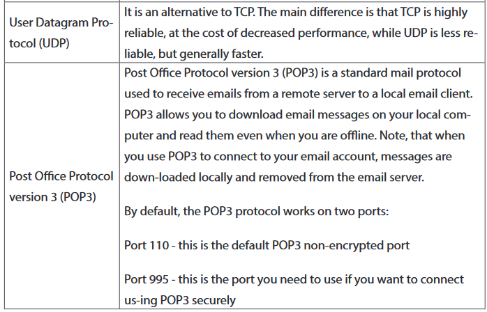
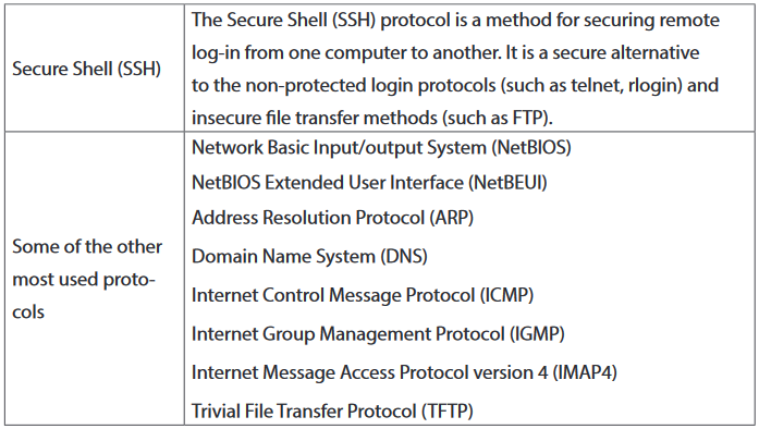
2.5.1 Most used protocols
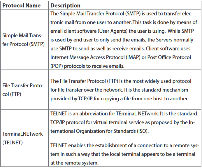
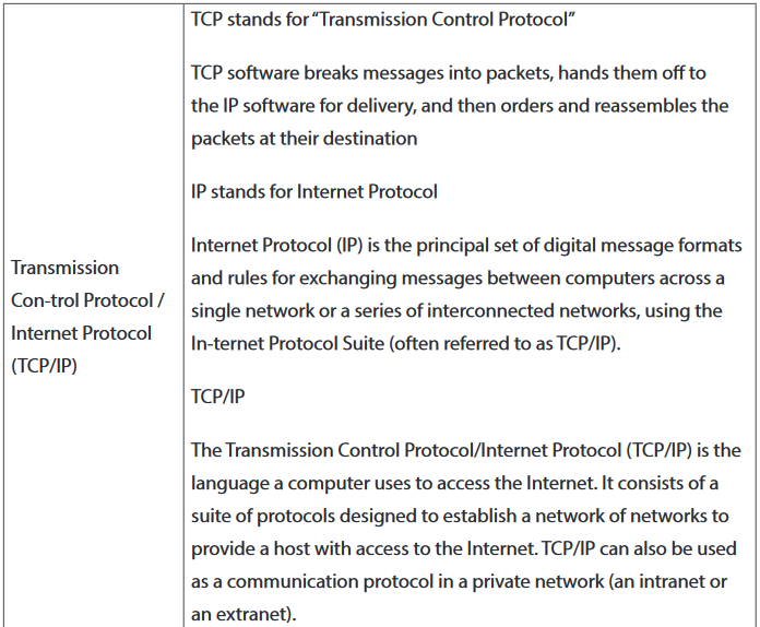
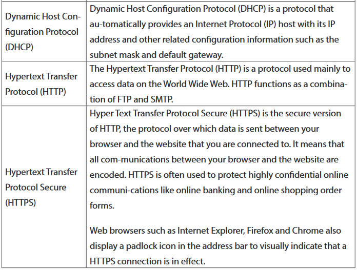
The most used protocols with their descriptions are given in the following table.

Application activity 2.5:
1. Discuss the role of protocols in computer communication?
2. Search on Internet a free application called FileZilla Client and FileZilla Server using FTP to get access remotely to documents on another computer in the school computer lab. Copy to /from any document between the 2 computers.
2.6 OSI model
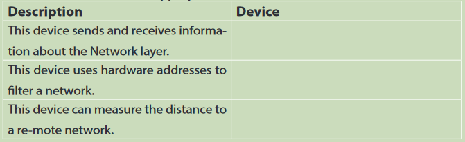
Activity 2.6:
Fill in the blanks with the appropriate device between hub, switch and router.
2.6.1 Definition
Open System Interconnect (OSI) is an open standard for all communication systems. OSI model is established by International Standard Organization (ISO). It is a general-purpose model for discussing or describing how computers communicate with one another over a network. Its seven-layered approach to data transmission divides the many operations up into specific related groups of actions at each layer
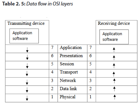
In the OSI model, data flows down the transmit layers, over the physical link, and then up through the receive layers. The transmitting computer software gives the data to be transmitted to the applications layer, where it is processed and passed from layer to layer down the stack with each layer performing its designated functions. The data is then transmitted over the physical layer of the network until the destination computer or another device receives it. At this point the data is passed up through the layers again, each layer performing its assigned operations until the data is used by the receiving computer’s software. The roles of OSI model layers are:

a. The Application Layer
The application layer enables the user, whether human or software, to access the network. It provides user interfaces and support for services such as domain name service (DNS), file transfer protocol (FTP), hypertext transfer protocol (HTTP), Internet message access protocol (IMAP), post office protocol (POP), simple mail transfer protocol (SMTP), Telenet, and terminal emulation. Devices used in this layer are Gateways, Firewalls, and all end devices like PC’s, Phones, and Servers.
b.The Presentation Layer
It presents data to the Application layer and is responsible for data translation and code formatting.
The presentation layer is concerned with the syntax and semantics of the information exchanged between two systems.
Specific responsibilities of the presentation layer include the following:
•Translation
•Encryption
•Compression
Devices which operate at this layer are Gateways, Firewalls and PC’s.
c. The Session Layer
The Session layer is responsible for setting up, managing, and then destroying down sessions between Presentation layer entities. This layer also provides dialogue control between devices, or nodes.
It coordinates communication between systems and serves to organize their communication by offering three different modes of communication: simplex, half duplex, and full duplex.
Specific responsibilities of the session layer include the following:
•Dialog control
•Synchronization
The devices used at this layer are Gateways, Firewalls, and PC’s.
d.The Transport Layer
The Transport layer segments and reassembles data into a data stream. Services located in the transport layer segment and reassemble data from upper-layer applications and unite it onto the same data stream. They provide end-to-end data transport services and can establish a logical connection between the sending host and destination host on an internetwork. At this layer we find devices like Gateways and Firewalls.
e. The Network Layer
The Network layer manages device addressing, tracks the location of devices on the network, and determines the best way to move data, which means that the Network layer must transport traffic between devices that are not locally attached. Routers (layer 3 devices) are specified at the Network layer and provide the routing services within an Internetwork.
The network layer is responsible for the delivery of individual packets from the source host to the destination host.
Two activities are performed:
•Logical addressing: IP addressing
•Routing: Source to destination transmission between networks
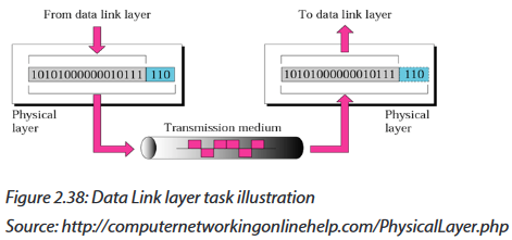
f. The Data Link Layer
The Data Link layer formats the message into pieces, each called a data frame, and adds a customized header containing the hardware destination and source address. This added information forms a sort of capsule that surrounds the original message.
To allow a host to send packets to individual hosts on a local network as well as transmit packets between routers, the Data Link layer uses hardware addressing.
Switches and bridges work at the Data Link layer and filter the network using hardware (MAC) addresses.
g.The Physical Layer
Finally arriving at the bottom, the Physical layer does two things: It sends bits and receives bits. Bits come only in values of 1 or 0. The Physical layer communicates directly with the various types of actual communication media.
The Physical layer specifies the electrical, mechanical, procedural, and functional requirements for activating, maintaining, and deactivating a physical link between end systems. This layer is also where you identify the interface between the data terminal equipment (DTE) and the data communication equipment (DCE). Devices like Hubs, Repeaters, Cables, and Fibers operate at this layer.

Notice that the following network devices operate on all seven layers of the OSI model:
-Network management stations (NMSs)
-Web and application servers
-Gateways (not default gateways)
-Network hosts
2.6.2 Advantages of using the OSI layered model
1. It divides the network communication process into smaller and simpler components, thus aiding component development, design, and troubleshooting.
2. It allows multiple-vendor development through standardization of network components.
3. It encourages industry standardization by defining what functions occur at each layer of the model.
4. It allows various types of network hardware and software to communicate.
5. It prevents changes in one layer from affecting other layers, so it does not hamper hardware or software development.
Application activity:
1. Which layer of the OSI model creates a virtual link between hosts before transmitting data?
2. What is the main reason of the creation of OSI model?
3. Describe each one of the 7 layers of the OSI model.
4. Which layer is responsible for converting data packets from the Data Link layer into electrical signals?
5. At which layer is routing implemented, enabling connections and path selection between two end systems?
6. Which layer defines how data is formatted, presented, encoded, and converted for use on the network?
7. Which layer is responsible for creating, managing, and terminating sessions between applications?
8. Search on Internet and propose the format of a packet sent between 2 computers through the
2.7 TCP/IP model
Learning activity 2.7:
One teacher at your school wants to send a 50MB file to students’ emails but when he tries to attach it the email server rejects because of the size limit. It says that it cannot upload files larger than 20MB.
1. What are other alternative to share this file?
2.7.1 Introduction
The TCP/IP protocol suite was developed prior to the OSI model. Therefore, the layers in the TCP/IP protocol suite do not exactly match those in the OSI model. TCP/IP model is the combination of TCP as well as IP models. This model ensures that data received is same as the data sent, and the data bytes are received in sequence. This model mainly defines how data should be sent (by sender) and received (by receiver). Most common examples of applications using this model include the email, media streaming, or World Wide Web (WWW). Presentation and session layers OSI model are not there in TCP/IP model.
TCP/IP model comprises 4 layers that are as follows:

1. Application Layer
Application layer is the top most layer of four layers TCP/IP model. Application layer is present on the top of the Transport layer. Application layer defines TCP/IP application protocols and how host programs interface with Transport layer services to use the network.
It groups the functions of OSI Application, Presentation and Session Layers. It includes protocols like:
-The Hypertext Transfer Protocol (HTTP) is used to transfer files that make up the Web pages of the World Wide Web.
-The File Transfer Protocol (FTP) is used for interactive file transfer.
-The Simple Mail Transfer Protocol (SMTP) is used for the transfer of mail messages and attachments.
-Telnet, a terminal emulation protocol, is used for logging on remotely to network hosts.
2. Transport layer
Transport Layer (also known as the Host-to-Host Transport layer) is the third layer of the four layer TCP/IP model. The position of the Transport layer is between Application layer and Internet layer. The purpose of Transport layer is to permit devices on the source and destination hosts to carry on a conversation. Transport layer defines the level of service and status of the connection used when transporting data. It is responsible for providing the Application layer with session and datagram communication services.
The core protocols of the Transport layer are Transmission Control Protocol (TCP) and the User Datagram Protocol (UDP).
-TCP provides a one-to-one, connection-oriented, reliable communications service. TCP is responsible for the establishment of a TCP connection, the sequencing and acknowledgment of packets sent, and the recovery of packets lost during transmission.
-UDP provides a one-to-one or one-to-many, connectionless, unreliable communications service. UDP is used when the amount of data to be transferred is small (such as the data that would fit into a single packet).The Transport layer encompasses the responsibilities of the OSI Transport layer and some of the responsibilities of the OSI Session layer.
3. Internet layer
The Internet layer is responsible for addressing, packaging, and routing functions. The core protocols of the Internet layer are IP, ARP, ICMP, and IGMP.
-The Internet Protocol (IP) is a routable protocol responsible for IP addressing, routing, and the fragmentation and reassembly of packets.
-The Address Resolution Protocol (ARP) is responsible for the resolution of the Internet layer address to the Network Interface layer address such as a hardware address.
-The Internet Control Message Protocol (ICMP) is responsible for providing diagnostic functions and reporting errors due to the unsuccessful delivery of IP packets.
-The Internet Group Management Protocol (IGMP) is responsible for the management of IP multicast groups.The Internet layer is analogous to the Network layer of the OSI model.
4. Network Access Layer
This layer basically controls hardware devices and media that make up the network. Its tasks include routing of data, sending it over the network, verifying the data format, and converting the signs from analog to the digital format. TCP/IP can be used to connect differing network types. These include LAN technologies such as Ethernet and Token Ring and WAN technologies such as X.25 and Frame Relay.
The Network Interface layer encompasses the Data Link and Physical layers of the OSI model.
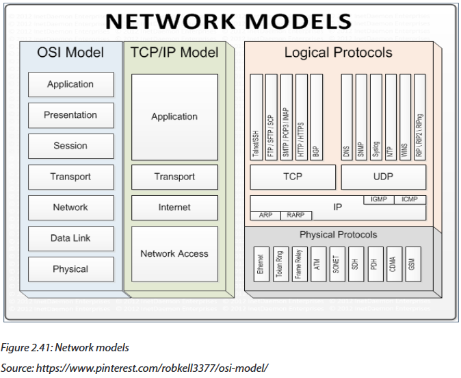
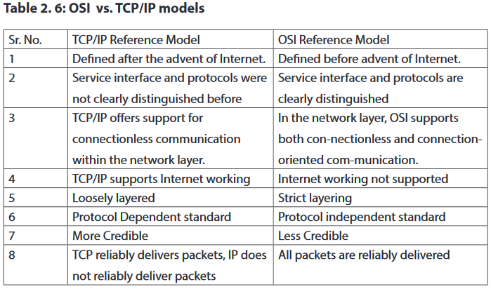
2.7.1 Summary of network models
The 2 network models do realize the same job of sending data between different networks. By comparing OSI and TCP/IP models, there is a difference because the number of layers differs. However, some layers like application in TCP/IP do the job done by many layers in OSI models. For example Application layer and Network layer in TCP/IP combine the role of many layers.
Application activity 2.7:
1. Which of the following are layers in the TCP/IP model? (Choose three.)
a. Application
b. Session
c. Transport
d. Internet
e. Data Link
f. Physical
2. What layer in the TCP/IP stack is equivalent to the Transport layer of the OSI model?
a. Application
b. Host-to-Host
c. Internet
d. Network Access
3. Using a figure, describe TCP/IP and OSI network models with their associated protocols.
4. Describe the purpose and basic operation of the protocols in the OSI and TCP models.
2.7.1 Network switching
Learning activity 2.8:
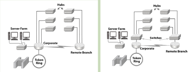
Look at the following two network designs represented by figure A and B and answer questions:
5. Describe what you see.
6. What is the difference between these two designs?
2.8.1 Definition
Switching is a process to forward packets coming in from one port to a port leading towards the destination. When data comes on a port it is called ingress, and when data leaves a port or goes out it is called egress.
A switched network consists of a series of interlinked nodes, called switches. In a switched network, some of these nodes are connected to the end systems (computers or telephones, for example). Others are used only for routing. The Figure below shows a switched network.
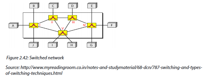
The end systems (communicating devices) are labeled A, B, C, D, and so on, and the switches are labeled I, II, III, IV, and V. Each switch is connected to multiple links.
The advantages of switches are as follows:
-Switches increase available network bandwidth
-Switches reduce the workload on individual computers
-Switches increase network performance
-Networks that include switches experience fewer frame collisions because switches create collision domains for each connection (a process called micro segmentation)
-Switches connect directly to workstations.
2.8.2 Switching methods
The classification of switched networks is given by the figure below.

2.8.2.1 Circuit-Switched Networks
Circuit switching is a switching method in which a dedicated communication path in physical form between two stations within a network is established, maintained and terminated for each communication session. Applications which use circuit switching may have to go through three phases:
•Establish a circuit
•Transfer the data
•Disconnect the circuit
2.8.2.2 Packet Switched Networks
In packet switched data networks all data to be transmitted is first broken down into smaller chunks called packets. The switching information is added in the header of each packet and transmitted independently.
It is easier for intermediate networking devices to store small size packets and they do not take much resources either on carrier path or in the internal memory of switches.

Packet switching can be done through the following technologies:
g. Datagram networks
Packets are treated independently and may take different routes. Datagram is better if numbers of packets are not very large.
h. Virtual circuit networks
In virtual circuit, a logical path is setup prior the transmission and therefore, no routing decision is to make which ensure that packet are forwarded more quickly than datagram. The logical path between destination and source also assure the sequencing of packet and better error control. However, virtual circuit is less reliable because Interruption in a switching node loses all circuit through that node.
2.8.2.3 Message switching
In message switching, if a station wishes to send a message to another station, it first adds the destination address to the message. Message switching does not establish a dedicated path between the two communicating devices i.e. no direct link is established between sender and receiver. Each message is treated as an independent unit.
Consider a connection between the users (A and D) in the figure below (i.e. A and D) is represented by a series of links (AB, BC, and CD).
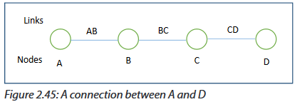
For example, when an email message is sent from A to D, it first passes over a local connection (AB). It is then passed at some later time to C (via link BC), and from there to the destination (via link CD). At each message switch, the received message is stored, and a connection is subsequently made to deliver the message to the neighboring message switch.
Application activity 2.8
1. How does the message switching differ from circuit switching?
2. Explain the technologies used in packet switching.
END UNIT ASSESSMENT ACTIVITIES
1. Your school has acquired 60 computers from the Rwanda Education Board (REB) and wishes to distribute them as follows:
- Administration: 3 computers
- Staff room: 7 computers
- Computer lab for students in Ordinary level: 30 computers
- Computer lab for students in Advanced level: 20 computers
a. List and describe specifications of all materials needed to setup 2 wireless LANs within the school.
b. Is it possible to secure those wireless networks?
c. Indicate the type of wireless security to be used.
2. Discuss the advantages of Fiber optic cables within a LAN.
3. Why routers and switches do not operate at the same OSI reference model layer?
4. What are the common steps in configuring both wireless router and access points?
5. Is it possible to change the default gateway of your computer? Explain.
6. When and how both public and private IP addresses are used within the same network?
7. Describe the purpose and basic operation of the protocols in the OSI and TCP models.
8. What are the advantages of using OSI layered model?
9. Discuss the importance of switches within a LAN.