Topic outline
UNIT 1: COMPUTER SECURITY
Key Unit Competency:
To be able to enumerate various security threats and ensure security of computer.
INTRODUCTORY ACTIVITY
A. Apply the following scenario.
1. In the school computer lab, some computers have been damaged by humidity, some computer screens that have been broken and other computers are not password protected. In groups, respond to the following questions. What is wrong with such A computer lab?
2. Identify the risks of an unsecured computer
3. Describe how this computer lab can be secured
4. Describe how data stored in a computer can be protected
5. What are the measures that can be considered to protect the computer lab physically and logically?
Describe what you see on the picture bellow.
1. Is this computer lab well organized?
2. Identify the security risks.
3. Propose solutions to improve the security of material inside this computer lab
1.1 Why computer security?
ACTIVITY 1.1
Visit the school computer lab and answer the following questions?
1. In the school computer lab, are all computers secured? If yes, describe how they are secured. If not, what to do to enhance the security of computers?
2. Describe the simple measures that can be taken to protect the computers in the school computer lab
Introduction
Nowadays, computers become an indispensable tool in the life of human beings. They are used in banking, in shopping, in communicating between people through emails and chats, etc. However, some intruders are joining the conversations and try to read emails of others without permission. Most of the time, they misuse their computers by attacking other systems, sending forged emails from computers, or examining personal information stored in others’ computers.
Computer security refers to techniques developed to safeguard information and systems stored on computers.
The protection of data (information security) is important. It reduces the probability of hardware and software problems and it increases the security of data stored in computers.
Why is computer security important?
Computer security is important for many reasons:
Computer security helps to keep safely data and equipment functioning properly and provide access only to appropriate people.
Computer security prevent unauthorized persons to enter in others computers without their consents.
Computer security helps to keep healthily computers against viruses, malware and other unintentional soft wares that can prevent computers to run smoothly.
Computer network need to be protected because Cyber criminals, hackers, and identity thieves present real and dangerous threats to any online system.
APPLICATION ACTIVITY 1.1
1. By using simple words, define computer security?
2. In pairs, discuss and write a brief report on importance of computer security at your school, in Rwanda and in the whole world.
3. Write down some cases of computer security break that have happened in Rwanda and in the world?
1.2 Computer threats
LEARNING ACTIVITIES 1.2
A hard disk is connected into a broken computer system case like the one below. When the computer is switched on, it shows that something is wrong. The user cannot work on it properly. It is very difficult to send a document to hard disk.
1. Describe what is happening to make the computer not functioning correctly.
2. Propose solutions to this problem
1.2.1 Threat definition
A threat, in the context of computer security, refers to anything that has the potential to cause serious harm to a computer system. A threat is an activity/ attack/ situation that may happen, with the potential to cause serious damage. Threats can lead to attacks on computer systems, networks and more.
1.2.2 Threat categories
Knowing how to identify computer security threats is the first step in protecting a computer. The threats could be intentional, accidental or caused by natural disasters. Computer threats are categorized in two categories; physical threats and logical threats:
Physical threats
Digital storage media and hardware are subject to numerous internal and external forces that can damage or destroy their readability. Below are some cases of physical threats:
•Improper storage environment (temperature, humidity, light, dust),
•Over use (mainly for physical contact media),
•Natural disaster (fire, flood, earthquake),
•Infrastructure failure (plumbing, electrical, climate control),
•Inadequate hardware maintenance,
•Hardware malfunction
Logical threats
Are events or attacks that remove, corrupt, deny access, allow access, or steal information from a computer without physical presence of somebody. These include viruses, worms, Trojans, spyware, adware, SQL injection etc.
Threats to information systems can cause:
•Hardware failure: A malfunction within the electronic circuits or electro mechanical components (disks, tapes) of a computer system. Example: a CPU socket damaged.
•Software failure: The inability of a program to continue processing due to erroneous logic. Example: a crash of a computer program.
•Electrical problems: are faults caused by electric like a low-resistance connection between two points in an electric circuit through which the current tends to flow rather than along the intended path.
•User errors: is an error made by the human user of a computer system in interacting with it. Example: a system file deleted unintentionally by a user.
•Telecommunication problems. Example: when the antenna are not working
•Program changes; modifications made to program. Example: a simple modification in a program can affect the whole software.
•Theft of data, software, services and equipment. When a physical or logical component of a system is stolen, the whole system stops. Example: a computer cannot run without a RAM or cannot run with a corrupted software
APPLICATION ACTIVITY 1.2
1. Discuss the difference between logical and physical threats and give examples for each?
2. Explain the difference between hardware and software failure
3. Explain how a computer user can cause the errors to information system.
4. In the school computer lab, take one computer and remove the RAM. What is happening to the system?
5. After analyzing the school computer lab, enumerate the different threats that are existing with the computer
1.3 Computer attacks
LEARNING ACTIVITY 1.3.
Suppose that yesterday when students were using computers in the school computer lab, everything worked well. They brought from outside different storage devices like flash disks and external hard disks used to copy various documents to the computers. Today morning, when the Lab attendant switched on the computers, most of them displayed suspected messages.
Discuss in groups what may be the cause of such behaviors. How the problem can be addressed in the laboratory?
In computer and computer networks an attack is any attempt to expose, alter, disable, destroy, steal or gain unauthorized access to or make unauthorized use of an asset. An attack can be active or passive.
An “active attack” attempts to alter system resources or affect their operation.
A “passive attack” attempts to learn or make use of information from the system but does not affect system resources.
The different kinds of attacks are summarized in the following image:
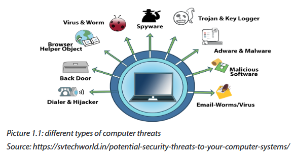
However, the frequent computer attacks are virus, worms, Trojan, spyware, Shoulder Surfing, Denial-of-Service, eavesdropping, social engineering and cyber crimes
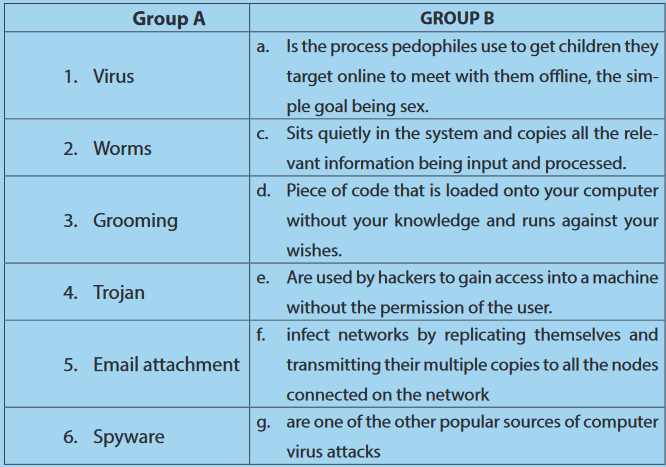
1.3.1 Virus
A virus is a self-duplicating computer program or piece of code that is loaded onto a computer without the user’s knowledge and runs against his/her wishes.Viruses can spread themselves from computer to computer, interfering with data and software. A virus is attached to small pieces of computer code, software, or documents. The virus executes when the software is run on a computer. If the virus is spread to other computers, those computers could continue to spread the virus.
Some viruses work by hiding on the first sector of a disk and loaded into memory. Other viruses insert themselves onto program files that start applications. Those files have the extension of .exe and .com the last category of viruses are viruses which infect programs that contain powerful macro languages like programming languages.
The common viruses are:
a. Worms
A worm is a computer program that sits in the computer memory, duplicates itself continuously until the system runs out of memory and crashes. Worms infect networks by replicating themselves and transmitting their multiple copies to all the nodes connected on the network.
b.Trojan
A Trojan may appear to be something interesting and harmless, such as a game, but when it runs it may have harmful effects. Unlike worms, Trojans do not replicate themselves but they are destructive.
Trojan are used by hackers to gain access into a machine without the permission of the user.
Normally when someone visits some websites which are malicious in nature, the trojan gets downloaded or may come from an infected source.
The Trojan gets installed in the computer and later on helps the hackers to gain access into that computer.
1.3.2 Denial of Service (DoS)
When a denial of service (DoS) attack occurs, a computer or a network user is unable to access resources like e-mail and the Internet. An attack can be directed at an operating system or at the network.
1.3.3 Spyware
Just like virus, Spyware also comes under that category of malware attacks, which means that it is a code or program written for doing some damage to the computer.
Although the working of spyware is different from the other types of malware mentioned, Spyware as the name suggests is used to spy into a system.
The job of the spyware is to silently sit inside the host system and observe the activities of the system.It may also come from other sources like detachable storage devices. Spyware sits quietly in the system and copies all the relevant information being input and processed.
Example of how spyware work:
Suppose a user is logging on to any bank.
Once the website of the bank opens, the user id and login password is input.
After that if the user wants to do a financial transaction, the transaction password has to be entered. All this information is quietly registered by the spyware. Then the spyware sends all the information recorded from the user’s computer to its parent i.e. probably a hacker somewhere on the Internet. The information may be transmitted even while the user is using the system.
Once the hacker has the user’s information, like bank name, login id and password, nothing can stop him/her from transferring the money from that account to anywhere else.
APPLICATION ACTIVITY 1.3a
1. What is a computer attack? Differentiate active attack to passive attack.
2. Explain the difference between worms and Trojan
3. Explain briefly how virus are categorized?
1.3.3 Social Engineering
A Social Engineer is a person who is able to gain access to equipment or a network by tricking people into providing him/her the necessary access information. Often, the Social Engineer gains the confidence of an employee and convinces him/her to divulge username and password information.
A Social Engineer may pose as a technician to try to gain entry into a facility. Once inside, he/she may look over shoulders to gather information, seek out papers on desks with passwords, or obtain a company directory with e-mail addresses.
So, Social Engineering is a technique/method used by someone by trying to socialize with someone else with the purpose of picking/getting his/her credentials or user name and password with intention to use them during his/her absence. A user never feels that revealing his/her credentials to someone that he/she trusts is wrong.
Example:
•A husband gives his credentials to her wife and vice versa.
•An Administrative Assistant gives his/her credentials to his/her boss.
•Etc
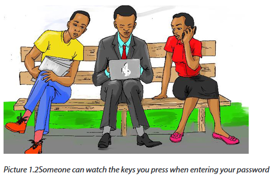
1.3.4 Shoulder Surfing
In computer security, shoulder surfing is a type of social engineering technique used to obtain information such as personal identification number, password and other confidential data by looking over the victim’s shoulder. This attack can be performed either from a closer range by directly looking over the owner of information.
1.3.5 Eavesdropping
Eavesdropping refers to the unauthorized monitoring of other people’s communications. It can be conducted on ordinary telephone systems, emails, instant messaging or other Internet services.
1.3.6 Cybercrimes
Cybercrime, also called computer crime, is any illegal activity that involves ICT tools such as a computer or network-connected device, such as a mobile phone.
Different types of cybercrimes:
•Cyberbullying
Cyberbullying is bullying that takes place using electronic technology. Electronic technology includes devices and equipment such as cell phones, computers, and tablets as well as communication tools including social media sites, text messages, chat, and websites.
Examples of cyberbullying include text messages, rumors sent by email or posted on social networking sites, and embarrassing pictures, videos, websites, or fake profiles, posting hurtful images, making online threats, and sending hurtful emails or texts.
Example: when someone tweets or posts on social media:
Today, the president of United States resigns because he failed to supply laptops in schools.
•Sexting
Sexting is the sending and receiving of text, photo or video messages of children and young people that are inappropriate and sexually explicit.
These images are mostly self-generated and shared through mobile phone MMS, Skype and social networking sites where images can be posted and shared such as Facebook, WhatsApp, Twitter, Tumblr, Flickr, YouTube, Instagram, Snapchat etc.
•Grooming
“Grooming” is the way sexual predators get from bad intentions to sexual exploitation. Sometimes it involves flattery, sometimes sympathy and other times offers of gifts, money, transportation, or modeling jobs.
1.3.7 Website hacking
1.3.7.1 Definitions
Hacking
Hacking is a term used to describe actions taken by someone to gain unauthorized access to a computer belonging to other people. It is the process by which cyber criminals gain access to your computer. After entering in that computer, a hacker can find weaknesses (or preexisting bugs) in the security settings and exploit them in order to access available information. He/she can also install a Trojan horse, providing a back door for hackers to enter and search for your information.
1.3.7.2 Website hacking techniques
Most of the information belonging to different individuals or institutions either private or public bring attention of outsiders who may want to break inside. The use of this information differ according to the interest of its users. The owners or administrators of websites should then put in place measures to protect their information and the users. There exist different techniques used by hackers and hence, there are many tools to deal with many kinds of theft and protect the websites.
Rwanda Information Society Authority (RISA) has pledged stronger cooperation with the public in enhancing cyber security for all computers in Rwanda amid an alert over an outbreak of a security attack that has affected over 150 countries. According to a statement, the cyber security attack is known as ransomware and bears different variations like WannaCrypt, WannaCry, WannaCryptor or Wcrya. The broad based ransomware attack has appeared in at least eight Asian nations, a dozen countries in Europe, Turkey and the United Arab Emirates and Argentina and appears to be sweeping around the globe, researchers said. The cyber-attack mostly affects computers that run Microsoft Operating Systems, by automatically encrypting the files and blocking the user’s access to the entire system. Over the last decade Rwanda’s strong growth through ICT promotion has brought untold opportunities and prosperity in the country. And as we globally face this challenge in cyber security, as a country we strongly believe that an integrated strategy to ensure effective regulation to our cyber security is significant at this point.
To mitigate this outbreak, RISA gave a set of actions to ensure lasting national prevention and protection:
1. Users are required to maintain daily backups of critical data including application, databases, mails systems, and user’s files. Backups should be regularly tested for data restoration.
2. All computers should be installed with latest security updates (specifically including MS17-010. Patch)
3. Until the security patch is applied, the Server Message Block v1 (SMB v1) should be disabled on all computers.
4. The LAN perimeter firewall should be configured with a rule to block all incoming SMB traffic on port 445.
5. All computers should be upgraded to Windows 10 to benefit from the latest protection from Microsoft. The Windows Defender Antivirus, which can detect the above malware, should also be enabled on all Windows systems.
6. Ensure your Antivirus signatures are up to date as major vendors are all working to deliver updated signatures to detect/ prevent this.
7. All users are advised not to open any suspicious email especially one that has an attachment, furthermore all users are advised not to download any files that they are not sure of the source.
Comprehensive action to strengthen our information and communication Technology sector countrywide is taken. However, in case of any compromise or attack, RISA advises that the affected computer/PC must be removed from the network and the incident must also be reported to Rwanda Computer Security Incident Response team with immediate effect.
WannaCry exploited a vulnerability in the Windows operating system and was among a large number of hacking tools and other files that a group known as the Shadow Brokers released on the internet. Shadow Brokers said that they obtained it from a secret NSA server.
The identity of Shadow Brokers is unknown though many security experts believe the group that surfaced in 2016 is linked to the Russian government.
1.3.8 Unwanted content
During the use of internet, some webmasters through the usage of cookies and other applications had managed that when someone is navigating in a given website, unwanted webpages are opened. This happens mostly for advertising of other products or services rendered by other institutions or companies that contracted the webmasters. Or, it happens by itself with malicious software.
1.3.9 Pornography and violence
1.3.9.1 Pornography
These are images and video whose focus is on n sex or sexual arousal either directly or indirectly. In that group of videos, many films on pornography are produced and sold all over the world. This kind of films hurts adults, children, couples, families, and society.
Families, Non-Government Organizations and government institutions in charge of education and social welfare need to fight seriously against it malpractice which addict our society and hence affect the whole development.
In Rwanda, the institutional and national ICT policies contain articles prohibiting to watch pornographic film in offices. The selling of these films is also officially banned.
1.3.9.2 Cyber violence
Cyber violence is defined as online behavior that constitutes or leads to assault against the well-being (physical, psychological, emotional) of an individual or group.
What distinguishes cyber violence from traditional off-line forms of violence is that in the former case, some significant portion of the behavior takes place online, although it may even be carried out in offline contexts. There exist four basic types of cyber violence namely online contact leading to off-line abuse, cyber stalking, online harassment, degrading representations.
1.3.10. Hate media and unwanted content
The hate media is a form of violence, which helps to demonize and stigmatize people that belong to different groups of society. This type of media has incited haters among citizens and in some cases influenced most of the genocide that the world has known.
APPLICATION ACTIVITY 1.3 b
1. Which types of computer attacks had happened your school computer lab or in Rwanda or in sub region?
2. How to recognize that a document in a computer is infected by virus?
3. Explain what is social engineering in computer security;
4. Explain the difference between social engineering and Shoulder Surfing techniques;
5. Explain the different types of cybercrimes
1.4 Sources of virus and other attacks
LEARNING ACTIVITIES 1.4
In the school computer lab, when one student inserted a flash disk in one computer, he/she gets a virus detection message and all files are immediately deleted and the flash disk becomes empty
Another student discovers that when he/she opens a document in my MS Word, the content is displayed in unknown characters.
The last students gets a message that looks like the one below:
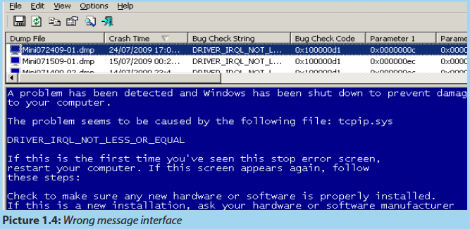
In groups, discuss what should be the causes for such problems.
Source of viruses
Virus infection in computers can be contacted through different means. Below are the common causes of computer virus attack.
A. Internet
It can not be denied that internet is one of the common sources of virus infection. This fact is not a real surprise and there is no point to stop using internet henceforth. Majority of all computer users are unaware as when viruses attack computer systems. Almost every computer user click/download everything that comes their way and therefore, unknowingly, invites the possibility of virus attacks.
B. Downloadable Programs
One of the possible sources of virus attacks is downloadable programs from the web. Unreliable sources and internet newsgroups are one of the main sources of computer virus attacks. Downloadable files are one of the best possible sources of virus. Any type of executable program including games, freeware, screen savers as well as executable files are one of the major sources of computer virus attacks.
C. Cracked Software
Cracked Software proves to be yet another source of virus attacks. Most people who download cracked and illegal versions of software online are unaware of the reality that they may contain virus sources as well. Such cracked forms of illegal files contain viruses and bugs that are difficult to detect as well as to remove.
D.Email Attachments
Email attachments are one of the other popular sources of computer virus attacks. Hence, you must handle email attachments with extreme care, especially if the email comes from an unknown sender. Installation of a good antivirus is necessary if one desires to eliminate the possibility of virus attacks.
E. Removable media
Removable media such as CDs, USB flash disks,... can be a source of viruses when the files they contain which may have been taken from other electronic devices, have been infected.
F. Bluetooth Transfer
Viruses can be contacted through a transfer of documents via a Bluetooth, once one of the computers is infected with a virus or the document to be transferred is infected.
APPLICATION ACTIVITY 1.4
1. Describe different ways of how internet is a virus source
2. Explain how CD is a source of virus in computer
1.5 Damage caused by Threats
LEARNING ACTIVITIES 1.5
From the previous lessons in this unit, different kinds of threats have been studied with their characteristics and their modes of contamination.
Discuss in groups the possible damages that they could cause in a computer, a school computer laboratory and in any network.
The consequences of the damages may vary according to the specific type of malware and the type of device that is infected plus the nature of the data that is stored on or accessed the device.
Whereas in some cases the results of a malware infection may be invisible to the user, in other cases the damage can have serious consequences.
Damages caused by threats:
For home users
-It can infect a computer if the user clicks on an infected banner or if he/she downloads and opens an attachment from a spam email or if he/she ends up on an infected website
-Harvest user’s data and send it to cyber criminal servers to use it in future attacks
-Destroy user’s data, it happens when the encryption key was not downloaded correctly and won’t work when trying to decrypt your data
-Hide from being detected by antivirus products because of its communication mechanisms
-Enlist your computer in a botnet and use its resources to launch attacks on other victims.
-Performance dropped when the user is not doing anything heavy.
On corporate network
-Web efacements and Semantic Attacks are used to propagate false information by changing the web page content subtly.
-In Domain Name Server (DNS) Attacks, when the user requests for a particular website to the DNS server, then he/she is diverted to an unwanted website because of a wrong Internet Protocol (IP) address generated by the DNS server (DHCP).
-Distributed Denial of Service (DDoS) Attacks involves high volume of communications to the targeted computers. It is the strategy that cyber attackers use to slow down those targeted computers.
-There are compound attacks whereby attackers can combine a number of attacks and make a series out of them which can destroy everything by leaving no possibility of recovery.
APPLICATION ACTIVITY 1.5
1. List and explain damages caused by virus in a computer system
2. List what damages caused by threats for home users
3. Enumerate other damages caused by virus that are not listed above
4. Use an example, explain how virus damage can reduce the production of any institution
1.6 Threats protection and precaution
ACTIVITY 1.6
In the school computer laboratory, to enter in a secured computer with password, someone needs to be given that password. If it has been forgotten, it becomes impossible to work with that computer. In groups, answer to the following questions:
1. What is the importance of login to computer with password?
2. List other security measures that can be used to protect a computer.
3. Explain how data stored in computer can be protected from damage?
As with any business asset, hardware, software, networks, and data resources need to be protected and secured to ensure quality, performance, and beneficial use.
They are four simple ways of protecting a computer:
1. To install antivirus software
2. To install firewall.
3. To install anti-spyware software.
4. To use complex and secure passwords.
Effective security measures can reduce errors, fraud, and losses.
1.6.1 Antivirus
i. Definition
Antivirus software are computer programs that attempt to identify, neutralize or eliminate harmful softwares. The term “antivirus” is used because the earliest lessons were designed to combat a wide range of threats, including worms, trojan and other malware. Antivirus software typically uses three different approaches to accomplish their tasks:
- The first way is to examine file looking like kwon viruses that match virus definition in virus dictionary
-The second way is to try and to recognize unusual behavior from a program which might signify a threat
-The last way is to prevent the execution of all computer codes which has not been identified as truth worthy
ii. Virus detection
An antivirus needs to scan the system in order to detect a security threat such as a virus. There exist 3 possible actions, depending to the user’s choice, when a virus has been found in a file:
• Move to quarantine: the infected file will be moved in protected repertory. It will thus be inaccessible and the code of the virus will not be executed.
• Repair/ Disinfect: the antivirus can also try to repair an infected file, i.e. to remove the code of the virus from the file. This is needed especially for program files.
• Delete: in this case, if the infected file cannot be repaired, there is no other alternative rather than deleting it. It is especially useful when this file is not essential to system, especially if it is not a program file.
After scanning an internal or external storage device, a report is generated in form of an interface. An example is shown below.
iii. Anti-Virus installation
In this case Kaspersky 2017 is going to be used as an example of how to install an antivirus.
Before the installation of Kaspersky 2017 on a computer, the following preparation has to be made:
•Make sure that the software is on external storage device or on another computer is a network;
•Check if the computer meets the requirements of Kaspersky Anti-Virus 2017;
•Make sure no antivirus software of Kaspersky Lab or other vendors is installed on your computer;
•Check if there is any incompatible software, remove it;
•Close all running applications;
Check if it is Kaspersky Anti-Virus 2017 installation under Windows 10, then click on the Desktop tile on the start screen.
Standard Installation:
1. Download the installation file from Kaspersky Lab website and run it. Then, the user follows the instructions given by the system.
2. If the antivirus Kaspersky installation file is saved in another computer of the same network, connect to that computer and run the executive file from it or displace it using a removable storage. The instructions will be followed as in the point above
3. Insert the disc into the CD/DVD drive if it contains the Kaspersky installation file. If the installation does not start automatically, run the installation file manually. Click Install.
4. Read the License Agreement in the window that appear afterward by clicking on the respective link. Accept its terms to install the application. Respond to other windows that may display in halfway during the installation
5. Wait until installation is completed. Make sure the Start Kaspersky Anti-Virus check box is selected, then click Finish.
Updating an antivirus
As mentioned above, new viruses are created every day. But if an antivirus is not aware of the signature of the newly developed virus, it will not know it and this enables the virus to attack the computer. It is important to regularly update the list of signatures of antivirus and if possible every day or at least after 3 days. These signatures are offered by the company which has developed the antivirus used. Signatures of viruses are kept in a database created by the company that created the antivirus. The steps to go through while updating an anti virus software depends on the type of that anti virus.
1.6.2 Anti spyware
Anti-spyware software is a type of program designed to prevent and detect unwanted spyware program installations and to remove those programs if installed. Detection may be either rule based or based on downloaded definition files that identify currently active spyware programs. Notice that most anti-virus software such as AVG contain inbuilt anti spyware software.
There exist many anti spyware software but the most popular are the following: AVG Anti Spyware, CheckFlow Anti Spyware 2005, CounterSpy, NoAdware, Avast and ScanSpyware
1.6.3 Firewall
Computers connected to communication networks, such as the internet, are particularly vulnerable to electronic attack because so many people have access to them. These computers can be protected by using firewall computers or firewall software placed between the networked computers and the network. The firewall examines, filters, and reports on all information passing through the network to ensure its appropriateness.
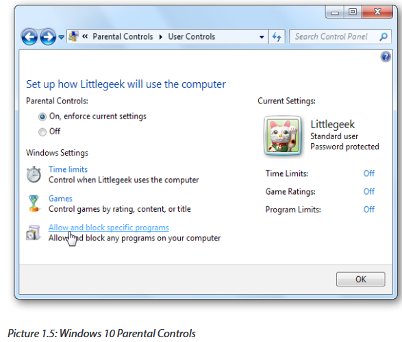
1.6.4 Parental Control
(Family Safety for any user)
The Parental Controls feature is a valuable tool for controlling the amount of time the children spend on the computer and the programs they’re using. Parental controls can filter the web, blocking inadvertent access to inappropriate websites.
1.6.5 Access control
Access control is a security technique that can be used to regulate who or what can view or use resources in a computing environment.
The access control model used by some operating systems ensures authorized use of its objects by security principles. Security principles include users and groups. Security principles perform actions on objects, which include files, folders, printers, registry keys and Active Directory.
Username and Password
The user can protect the access to the operating system. The administrator defines the passwords of users who are allowed to use the computer. If users do not enter the valid credentials (Username and Password), access will be denied.
•New account and password creation
1. From your current account, go to Settings > Accounts > Other People.
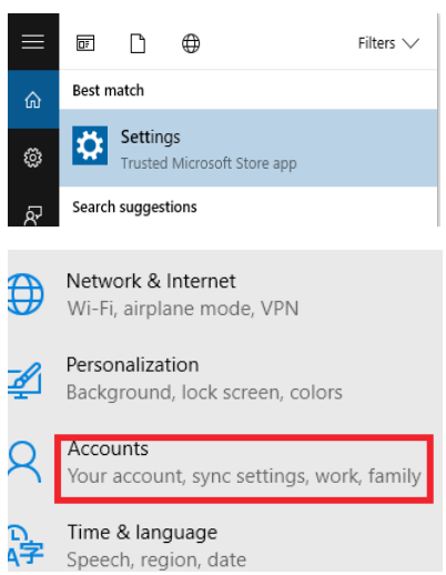
1. Click Add someone else to this PC.
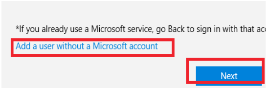
2. That dialog box wants you to enter the email address associated with a Microsoft account. Ignore that box and instead click I don’t have this person’s sign-in information.

3. The previous option opens a new dialog box that encourages you to create a new Microsoft account, which is not your goal. Ignore the fields at the top of this dialog box and instead click Add a user without a Microsoft account.
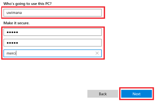
4. Now create that local user account, entering a short descriptive user name, a password you’ll be able to remember, and a password hint (which is mandatory).
1.6.6 Identification
Identification occurs when a user (or any subject) claims or professes an identity. This can be accomplished with a username, a process ID, a smart card, or anything else that can uniquely identify a subject. Security systems use this identity when determining if a subject can access an object.
In computer security, general access control includes authentication and authorization. Authentication and access control are often combined into a single operation, so that access is approved based on successful authentication, or based on an anonymous access token. Authentication methods and tokens include passwords, biometric scans, physical keys, electronic keys and devices.
*Authentication
Authentication is a process in which the credentials provided are compared to those on file in a database of authorized users’ information on a local operating system or within an authentication server. If the credentials match, the process is completed and the user is granted authorization for access. The permissions and folders returned define both the environment the user sees and the way he can interact with it, including hours of access and other rights such as the amount of allocated storage space.
Therefore, Authentication verifies the identity and authentication enables authorization
*Authorization
Authorization is the process of giving someone permission to do or have something. In multi-user computer systems, a system administrator defines for the system which users are allowed access to the system and what privileges of use (such as access to which file directories, hours of access, amount of allocated storage space, and so forth).
1.6.7 Biometric authentication
Biometric authentication is a security process that relies on the unique biological characteristics of an individual to verify that he/she is who is says he/she is. Typically, biometric authentication is used to manage access to physical and digital resources such as buildings, rooms and computing devices.
Types of biometric authentication technologies:
Retina scans produce an image of the blood vessel pattern in the light-sensitive surface lining the individual’s inner eye.
Iris recognition is used to identify individuals based on unique patterns within the ring-shaped region surrounding the pupil of the eye.
Finger scanning, the digital version of the ink-and-paper fingerprinting process, and works with details in the pattern of raised areas and branches in a human finger image.
Finger vein ID is based on the unique vascular pattern in an individual’s finger.
Facial recognition systems work with numeric codes called face prints, which identify 80 nodal points on a human face.
Voice identification systems rely on characteristics created by the shape of the speaker’s mouth and throat, rather than more variable conditions
1.6.8 Encryption and Decryption
Definition of Key Terms
Cryptography means “secret writing.” However, the term is used to refer to the science and art of transforming messages to make them secure and immune to attacks.
Encryption is the process of encoding a message or information in such a way that only authorized parties can access it. Encryption does not of itself prevent intervention, but denies the intelligible content to a would-be interceptor.
To read an encrypted file, you must have access to a secret key or password that enables you to decrypt it. Unencrypted data is called plain text; encrypted data is referred to as cipher text.
Decryption is the process of taking encoded or encrypted text or other data and converting it back into text that you or the computer can read and understand. This term could be used to describe a method of un encrypting the data manually or with un encrypting the data using the proper codes or keys. It is reversing encryption process
Cryptosystem: A combination of encryption and decryption methods
Cleartext or Plaintext: The original message, before being transformed, is called plaintext. After the message is transformed, it is called ciphertext. An encryption algorithm transforms the plaintext into ciphertext; a decryption algorithm transforms the ciphertext back into plaintext.
1.6.9 Data Backup and recovery point
a. Data backup
Just as the system restore points allow the restoration of operating system configuration files, backup tools allow the recovery of data. The user can use the Microsoft backup tool to perform backups as required.
Storing backup copies of data and having backup computer capabilities are important basic safeguards because the data can then be restored if it was altered or destroyed by a computer crime or accident. Here are some considerations for data backups:
•Computer data should be backed up frequently
•Should be stored nearby in secure locations.
•Transporting sensitive data to storage locations should also be done securely.
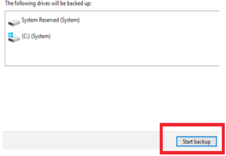
By using MS windows 10, the backup is done in this way:
1. Open control panel.
2. Click on system and security.

3. Click on backup and restore (windows 7).
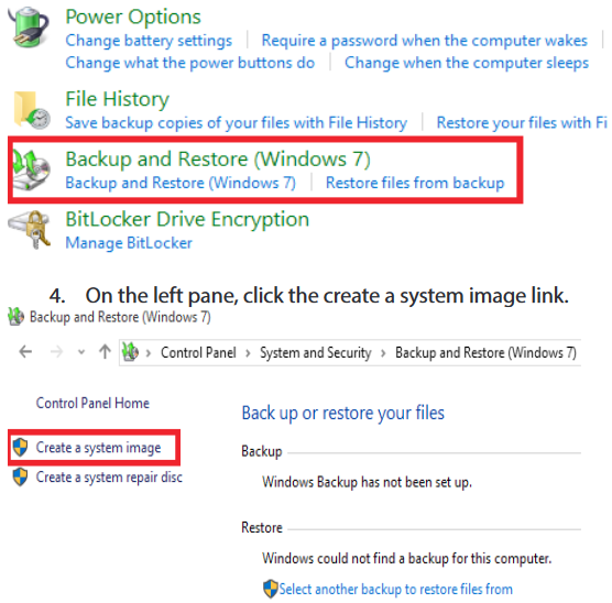
5. Under “where do you want to save the backup?” choose location.
6. Using the “on a hard disk” drop-down menu, select the storage to save the backup and click on start back up button
b. Recovery point
i. Fix problems with system restore
Microsoft Windows Operating System helps to recover from problems that might stop it from working properly, but there may come a time when it needs some manual intervention. Microsoft’s latest operating system has a similar set of recovery tools as easier versions for this, but not all work in the way you would expect and there are some new options at your disposal, too.
ii. System restore on windows 10
As with earlier versions of windows, system restore allows to ‘rewind’ windows installation to an earlier working state, without affecting the documents inside the computer. This is possible because windows automatically saves restore points when something significant happens, such as installing a windows update or a new application the idea being that if it goes wrong, the last restore point (or an even earlier one) can be returned back and get things performing as they were previously. The problem is that system restore is disabled by default in windows 10 and should therefore be enabled before benefiting from its features. Here is how to enable it:
•Open system restore
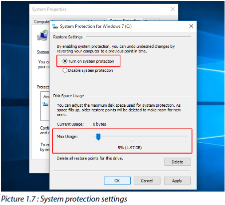
Search for system restore in the windows Operating System search box and select create a restore point from the list of results. When the system properties dialog box appears, click the system protection tab and then click the configure button. The following interface is coming from Microsoft Windows 10 Operating System.

•Enable system restore
Click to enable turn on system protection and then use the max usage slider to determine how much of your hard drive to use to store restore points — 5% to 10% is usually sufficient — and click OK. If you ever need to create a restore point manually, return to this dialog box and click the Create button, otherwise Microsoft windows 10 will create them automatically.
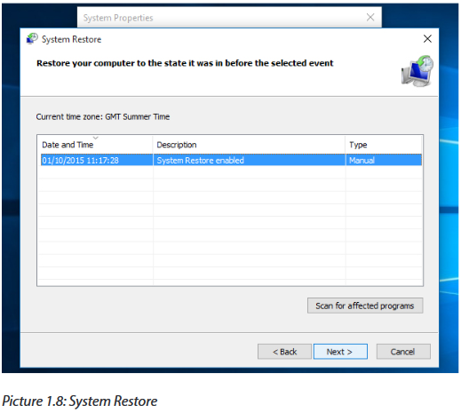
•Restore your PC
Whenever you want to return to a restore point, open the system properties dialog box again (see step 1), click the system protection tab and then click the System restore button. Follow the on-screen instructions and select the desired restore point when prompted. You can also click the scan for affected programs button before going any further, to see what might change on your PC afterwards. When you’re happy to proceed, click next.
a. If system restore doesn’t work event
Some serious windows problems can prevent you from rewinding to a restore point with system restore, but all is not lost. All you need to do is start windows 10 in safe mode. This bare bones windows mode only runs the essential parts of windows, which means any problematic apps, drivers or settings will be disabled. System restore will then usually be successful.
1. Open advanced start-up
Go to start > settings > update & security > recovery and click restart now below advanced start-up.

2. Start system restore in safe mode
Windows will then restart and display a choose an option menu. Select troubleshoot > advanced options > system restore and use system restore in the usual way.

b. Recovering from more serious problems
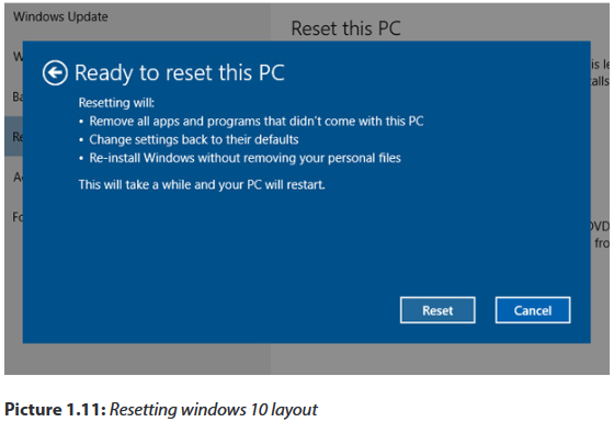
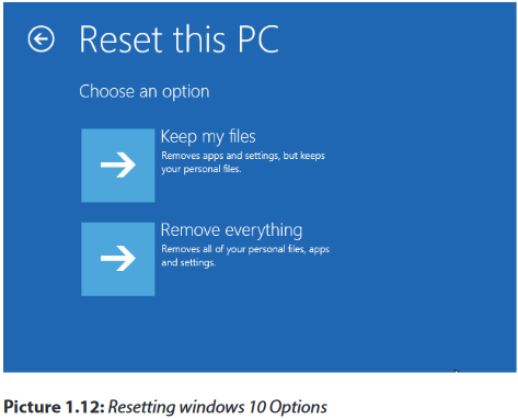
System restore won’t always rescue your PC from very serious problems, but windows 10 still has extra trick up its sleeve. It can restore windows to a factory fresh state without affecting your documents, although everything else (including apps) are removed. Even so, you should make sure you have a back up of your important files before using this option, just in case.
1. Open reset this PC
Go to start > settings > update & security > recovery and click get started below reset this PC.
2. Reset windows 10, but save your files
On the next screen, click keep my files and follow the on-screen instructions to reset windows 10. You’ll see a list of apps that will be removed and be asked to confirm your choice before going any further.
3. Reset this PC from safe mode
As with system restore, serious windows 10 problems can prevent reset this PC from working, but you can also run it from safe mode to bypass this. Follow step 1 under if system restore won’t work above, but instead choose troubleshoot > reset this PC > keep my files under step 2.
APPLICATION ACTIVITY 1.6
1. By using clear example, compare access control and parental control
2. In a bank, any customer can create and use an identity (e.g., a user name and password) to log into that bank's online service but the bank's policy must ensure that the user can only access to his/her individual ac-count online once his/her identity is verified.a. Identify which type of security is used in this bank?b. Why is it important?
3. What is the purpose of creating different computer users?
4. After anti-virus installation, where do you place the unusable CD and CD box?
5. At your school, the anti-virus used or installed in computers it was for haw many users?
Suppose that, the anti-virus keys are stolen by someone else to use it on network. What can be the consequences for that anti-virus users in that school? How the computer users can avoid that illegal action?
6. In the computer lab, configure the firewall
END UNITY ASSESSMENT
Part 1. Written
1. What is computer security? What is the purpose of computer security?
2. With an example, explain how you can protect a computer from physical threats?
3. Use three characters in an information exchange scenario; we use computers called Mulisa, Ndoli, and Kamana. Mulisa is the person who needs to send secure data.Ndoli is the recipient of the data. Kamana is the person who somehow disturbs the communication between Mulisa and Ndoli by intercepting messages to uncover the data or by sending her own disguised messages.
a. In the scenario, identify to whom belong clear text, plain text and ciphertext
b. Differentiate cipher tex to plaintext
4. Explain the difference between finger scanning and finger vein ID
5. By using example, explain access control in authorization
6. Which type of attack that enable a computer user to access his/her e-mail address?
7. What do you understand by social engineering technique? Give examples
8. It is heard that some web site become hacked by unknown people. Which strategies can be used to avoid young Rwandan programmers to engage in that action?
9. Using an arrow match the following in Group A with their corresponding in B
Part 2 Practice
In school computer lab, every student takes a computer and do the following activities:
1. With one external hard disk, make a backup of the local disk drive C
2. Update the anti-virus found on the computers
3. Add a new user on the computer
Files: 3UNIT 2: LAN ARCHITECTURE, NETWORK PROTOCOLS AND MODELS
Key Unit Competency: To be able to identify computer network models, protocols and configure network devices
Introductory Activity
Look at figure 2.1 below and answer the following questions:

1. Describe what you see.
2. Are the above computers communicating? How and why?
3. In which case the communication may not be possible?
4. What type of network does the figure above represent?
5. How the Computers A and B are connected?
6. Is there any other way of connecting A, B and C
2.1 LAN architecture
Activity 2.1:
Visit your school computer lab and look at the existing Network and answer the followings questions:
1. Describe how computers are connected to the Network?
2. Determine the type of the logical or physical arrangement of network devices (nodes) in that network.
2.1.1 Definition of LAN Architecture?
A Local Area Network (LAN) architecture is the overall design of a computers network that interconnects computers within a limited area such as a residence, school, laboratory, university campus of office building. The LAN architecture consists of three levels: Physical, Media Access Control (MAC) and Logical Link Control (LLC).
•The LLC provides connection management, if needed.
•The Media Access Control (MAC) is a set of rules for accessing high speed physical links and for transferring data frames from one computer to another in a network.
•The Physical level deals mainly with actual transmission and reception of bits over the transmission medium.
2.1.2 Major Components of LANs
A LAN is made of the following main components:
-Hardware:
◊ Computers
◊ Network interface card (NIC) linked to physical address
◊ Media or Cables (Unshielded twisted pair, Coaxial cable, Optical fiber, Air for wireless)
◊ Hub, Switches, repeaters
-Access Methods: Rules that define how a computer puts data on and takes it from the network cable.
-Software: Programs to access and / or to manage the network.
2.1.3 Aspects of LAN architecture.
These aspects include:
-LAN’s physical topology: defines how the nodes of the network are physically connected
-LAN’s logical topology: how data is transmitted between nodes
-LAN’s MAC protocol: used for the physical identification of different devices within the network
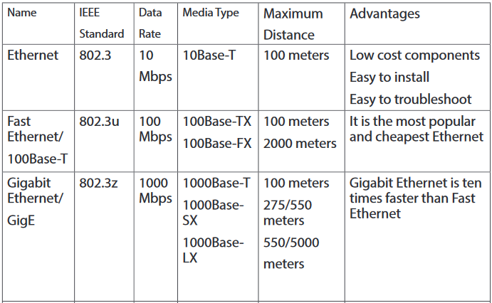
2.1.4 Ethernet
Ethernet is a family of computer networking technologies commonly used in local area networks, metropolitan area networks and wide area networks. Ethernet cable is one of the most popular forms of network cable used in wired networks. They connect devices together within a local area network like PCs, routers and switches. A standard Ethernet network can transmit data at a rate up to 10 Megabits per second (10 Mbps). Ethernet uses CSMA/CD (Carrier Sense multiple Access with Collision Detection)
2.1.5 Carrier Sense Multiple Access with Collision Detection (CSMA/CD)
In a LAN, computers transmit data to each other. Normally, there is order to follow so that two computers can not send data at the same time while they are using the same route. When it happens that two computers send messages at the same time, there is what we call data collision. Therefore, a data collision occurs when two or more computers send data at the same time. When this happens, each computer stops data transmission and waits to resend it when the cable is free. Carrier Sense Multiple Access with Collision Detection (CSMA/CD) is a set of rules determining how network devices respond to a collision.
How does the CSMA/CD work?
Consider the following picture:

On the figure above, host A is trying to communicate with host B. Host A “senses” the wire and decides to send data. But, in the same time, host D sends its data to host C and the collision occurs. The sending devices (host A and host D) detect the collision and resend the data after a random period of time.
When a collision occurs on an Ethernet LAN, the following happens:
•A jam signal informs all devices that a collision occurred.
A signal sent by a device on an Ethernet network to indicate that a collision has occurred on the network is called a jam signal.
•The collision invokes a random back off algorithm (a set of rules which controls when each computer resend the data in order to assure that no more collision will happen again).
•Each device on the Ethernet segment stops transmitting for a short time until the timers expire.
•All hosts have equal priority to transmit after the timers have expired.
Application activity 2.1:
1. Realize a physical topology using devices like router, switches, Hubs, Ethernet cables and 4 computers available in your school computer lab as indicated in Fig. 2.2.
2. Describe how does the CSMA/CD enable the communication over Ethernet?
2.2 Cable Ethernet Standards
Activity 2.2:
Look around your school computer lab and answer the following question:Observe and describe the communication media (different types of Cables) available there.
2.2.1 Definition of standard
Standards provide guidelines to manufacturers, vendors, government agencies, and other service providers in guaranteeing national and international interoperability of data and telecommunications technology and processes. With Ethernet technologies, different types of standards have been so far used in networks.
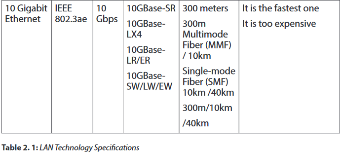
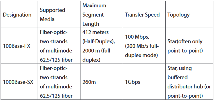
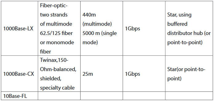
The different Ethernet technologies used in wired networks to connect computers are given in the following table. The choice of one or another type depends on the size of networks and the quantity of data to exchange.
10BASE-F
10BASE-F is a generic term for the family of 10 Mbit/s Ethernet standards using fiber optic cable. In 10BASE-F, the 10 represents its maximum throughput of 10 Mbit/s, BASE indicates its use of base band transmission, and F indicates that it relies on medium of fiber-optic cable. In fact, there are at least three different kinds of 10BASE-F. All require two strands of 62.5/125 μm multimode fiber.One strand is used for data transmission and one strand is used for reception, making 10BASE-F a full-duplex technology.
The 10BASE-F variants include 10BASE-FL, 10BASE-FB and 10BASE-FP. Of these only 10BASE-FL experienced widespread use. All 10BASE-F variants deliver 10 Mbit/s over a fiber pair. These 10 Mbit/s standards have been largely replaced by faster Fast Ethernet, Gigabit Ethernet and 100 Gigabit Ethernet standards.
10BASE-FL
10BASE-FL is the most commonly used 10BASE-F specification of Ethernet over optical fiber. In 10BASE-FL, FL stands for fiber optic link. It replaces the original fiber-optic inter-repeater link (FOIRL) specification, but retains compatibility with FOIRL-based equipment. The maximum segment length supported is 2000 meters.When mixed with FOIRL equipment, maximum segment length is limited to FOIRL's 1000 meters.
Today, 10BASE-FL is rarely used in networking and has been replaced by the family of Fast Ethernet, Gigabit Ethernet and 100 Gigabit Ethernet standards.
10BASE-FB
The 10BASE-FB (10BASE-FiberBackbone) is a network segment used to bridge Ethernet hubs. Due to the synchronous operation of 10BASE-FB, delays normally associated with Ethernet repeaters are reduced, thus allowing segment distances to be extended without compromising the collision detection mechanism. The maximum allowable segment length for 10BASE-FB is 2000 meters.
10BASE-FP
10BASE-FP calls for a non-powered signal coupler capable of linking up to 33 devices, with each segment being up to 500m in length. This formed a star-type network centered on the signal coupler. There are no devices known to have implemented this standard.
2.2.1 Wireless network standards
Wireless LANs (WLANs) use radio frequencies (RFs) that are radiated into the air from an antenna that creates radio waves.
Because WLANs transmit over radio frequencies, they are regulated by the same types of laws used to govern things like AM/FM radios. It is the Federal Communications Commission (FCC) that regulates the use of wireless LAN devices, and the IEEE takes it from there and creates standards based on what frequencies the FCC releases for public use.
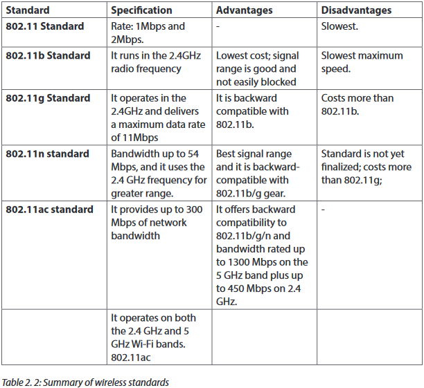
The wireless standards like the Ethernet standards are applied in different situations. The table below clearly describes each type.
2.2.3 Range, bandwidth and frequency
One characteristic that measures network performance is bandwidth. The bandwidth reflects the range of frequencies we need. However, the term can be used in two different contexts with two different measuring values: bandwidth in hertz and bandwidth in bits per second.
a. Bandwidth in Hertz
Bandwidth in hertz is the range of frequencies contained in a composite signal or the range of frequencies a channel can pass. For example, we can say the bandwidth of a subscriber telephone line is 4 kHz.
b.Bandwidth in Bits per Seconds
The term bandwidth can also refer to the number of bits per second that a channel, a link, or even a network can transmit per second. For example, one can say the bandwidth of a Fast Ethernet network is a maximum of 100 Mbps. This means that this network can send 100 Megabits per second.
2.2.3.1 Frequency and Network Range
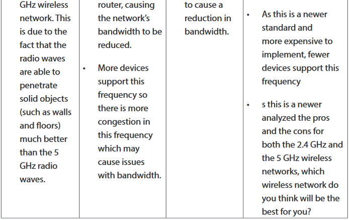
The higher the frequency of a wireless signal, the shorter its range. 2.4 GHz wireless networks therefore cover a significantly larger range than 5 GHz networks. In particular, signals of 5 GHz frequencies do not penetrate solid objects nearly as well as do 2.4 GHz signals, limiting their reach inside homes.
Many older Wi-Fi devices do not contain 5 GHz radios and so must be connected to 2.4 GHz channels in any case.
2.2.3.2 Range, Bandwidth and Frequency
•The term ‘Bandwidth’ refers to the speed at which data is transferred over the wireless network (more bandwidth means faster downloading and uploading)
•The term ‘Range’ refers to the maximum distance from the router at which the network can be received (the greater the range, the further you can be from the router and still be connected).
•The term ‘Frequency’ refers to the number of waves that pass a fixed place in a given amount of time. So if the time it takes for a wave to pass is is 1/2 second, the frequency is 2 per second. If it takes 1/100 of an hour, the frequency is 100 per hour.
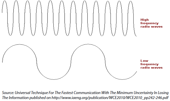
Usually frequency is measured in the hertz unit, named in honor of the 19th-century German physicist Heinrich Rudolf Hertz. The hertz measurement, abbreviated Hz, is the number of waves that pass by per second. For example, an "A" note on a violin string vibrates at about 440 Hz (440 vibrations per second).
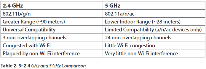
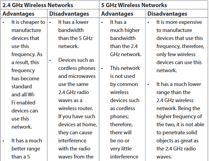
2.2.3.3 Advantages and Disadvantages of the 2.4 GHz and the 5 GHz Wireless Networks
2.2.3.4 Token ring
Token ring or IEEE 802.5 is a network where all computers are connected in a circular fashion. The term token is used to describe a segment of information that is sent through that circle. When a computer on the network can decode that token, it receives data.
A Multistation Access Unit (MSAU) is a hub or concentrator that connects a group of computers ("nodes" in network terminology) to a token ring local area network. For example, eight computers might be connected to an MSAU in one office and that MSAU would be connected to an MSAU in another office that served eight other computers. In turn, that MSAU could be connected to another MSAU in another office, which would be connected back to the first MSAU. Such a physical configuration is called a star topology. However, the logical configuration is a ring topology because every message passes through every computer one at a time, each passing it on to the next in a continuing circle.

Application activity 2.2:
Your school has classrooms, computer labs and the staff room located in three different buildings as indicated in the figure below:
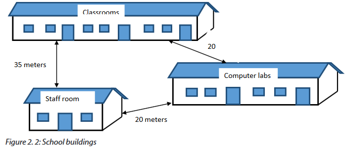
Questions:
1. Which kind of technology can you propose to connect computers in the 3 buildings. Explain you choice.
2. If you choose to install a wireless network within this school, in which building would you place the wireless device which serves the whole school? Explain.
3. What type of Ethernet cable would you use if you are requested to interconnect those three buildings? Explain.
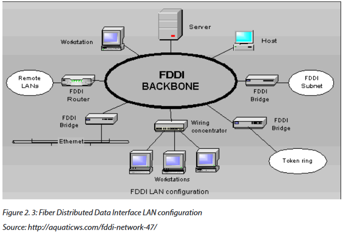
2.3 Fiber Distributed Data Interface (FDDI)
2.3.1 Definition
The Fiber Distributed Data Interface (FDDI) is a standard developed by the American National Standards Institute (ANSI) for transmitting data on optical fiber cables. FDDI supports transmission rates of 100 megabits per second on token-passing networks.
FDDI provides high-speed network backbones that can be used to connect and extend LANs.
2.3.2 Advantages of FDDI
The Fiber Distributed Data Interface allows the transmission of very large volumes of data over large distances. It provides high bandwidth.
2.3.3 Disadvantages
The Fiber Distributed Data Interface (FDDI) is an expensive technology to set up because the network devices require a special network card and also the required fiber optic cabling is expensive than twisted-pair cable. Because most Fiber Distributed Data Interface (FDDI) installations use a redundant second ring, more cabling is required.
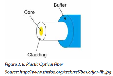
2.3.4 Fiber Optic cables
A fiber optic cable is a glass or plastic strand that transmits information using light and is made up of one or more optical fibers enclosed together in a sheath or jacket. It has the following properties:
•Not affected by electromagnetic or radio frequency interference.
•All signals are converted to light pulses to enter the cable, and converted back into electrical signals when they leave it.
•Signals are clearer, can go farther, and have greater bandwidth than with copper cable.
•Signal can travel several miles or kilometers before the signal needs to be regenerated.
•Usually more expensive to use than copper cabling and the connectors are more costly and harder to assemble.
•Common connectors for fiber-optic networks are SC, ST, and LC. These three types of fiber optic connectors are half-duplex, which allows data to flow in only one direction.
Therefore, two cables are needed.
a. Types of fiber optic
There are three types of fiber optic cable commonly used: single mode, multimode and plastic optical fiber (POF).
1. Single-mode: Cable that has a very thin core. It is harder to make, uses lasers as a light source, and can transmit signals dozens of kilometers with ease.

2. Multimode: Cable that has a thicker core than single-mode cable. It is easier to make, can use simpler light sources (LEDs), and works well over distances of a few kilometers or less.

3. Plastic optical fiber (POF):Transparent glass or plastic fibers which allow light to be guided from one end to the other with minimal loss.
The Fiber optic technologies are summarized in the following table.
Application activity 2.3:
4. Discuss the advantages and disadvantages of FDDI within a Local Area Network.
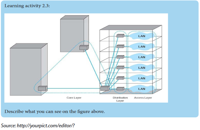
5. Referring to the figure on learning activity 2.3, what type of fiber optic cable would you recommend for the core and distribution layers? Explain.
2.4 Network devices
Activity 2.4.
In groups, look at the devices given below and answer the questions:
6. Describe the role of each one within a Local Area Network.
7. Explain how you can make a Local Area Network using the following devices?
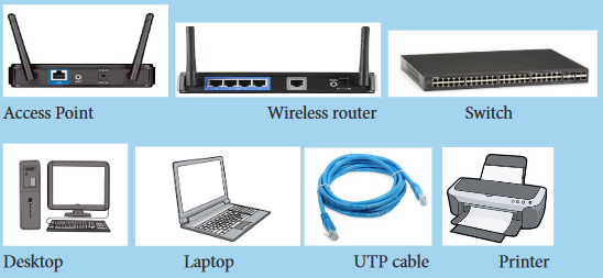
There are many networking devices: NIC cards, Repeaters, HUB, Bridges, Switches and Router
2.4.1 Wireless LAN cards (Network adapters)
Also called Network Interface Cards (NICs), they are connectivity devices enabling a desktop, server, printer, or other node to receive and transmit data over the network media
a. Types of Wireless Network Interface Cards (NICs)
NICs come in a variety of types depending on:
-The access method (for example, Ethernet versus Token Ring)
-Network transmission speed (for example, 100 Mbps versus 1 Gbps)
-Connector interfaces (for example, RJ-45 versus SC)
-Type of compatible motherboard or device (for example, PCI)
-Manufacturer (popular NIC manufacturers include 3Com, Adaptec, D
-Link, IBM, Intel,
-Kingston, Linksys, and so on)
b.Wireless NIC card installation and configuration
-Refer to the card manufacturer's quick
-start guide. Alternatively, you can also run the software installation program on the CD which comes with the PCI card and observe the steps to install it.
-Shut down the PC.
-Remove the cover.
-Locate an available PCI slot and remove the corresponding slot cover from the back of the PC.
-Carefully route the antenna through the open slot in the back of the PC, insert the card in the slot, and secure it. Replace the cover.
-Power up the PC. It should recognize and enable the new hardware.
c. Wireless NIC card Driver installation through the Device Manager
Step 1: Right-click on Computer (or PC) to select Manage.
Step 2: On the left, select Device Manager to bring it up on the right.

Step 3: Right click on the unknown adapter to Update Driver Software.
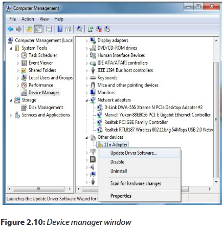
Step 4: Click to Search automatically for updated driver software.
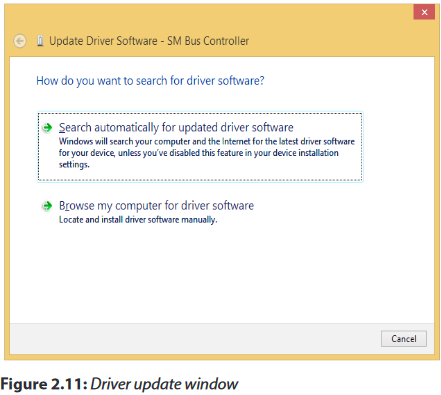
Step 5: Wait until the download process is successfully completed.
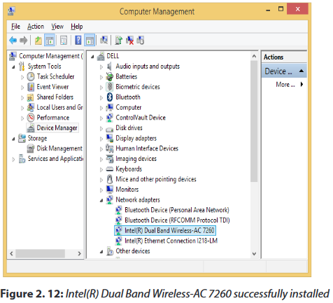
Step 6: Click on Save Settings or OK to apply the change.Confirmation of a successful Driver installation is achieved when the model of your adapter is labeled and listed in the Network adapters group of the Device Manager.
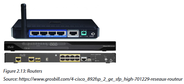
2.4.2 Routers and Access points
A wireless router is a device that performs the functions of a router and also includes the functions of a wireless access point. It is used to provide access to the Internet or a private computer network. Routers operate at the Network layer (Layer 3) of the OSI Model.
The Wireless access points (APs or WAPs) are networking devices that allow wireless Wi-Fi devices to connect to a wired network.
2.4.3 Configuring a wireless router
Step 1: Get to know your wireless router
•A power input jack one.
•One or more wired Ethernet jacks (often labeled 1, 2, 3, 4) for computers on your network which don't have wireless ability.
•One Ethernet jack for your broadband connection, often labeled “WAN” or “Internet.”
•A reset button. to
Step 2: Connect your router a wired PC for initial setup
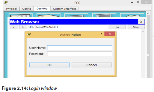
Step 3: Open web browser and connect to wireless router administration INTERFACE
To connect to your router, you need to know its default IP address and connect your browser to http://routeripaddress. For example, if you own a Linksys brand wireless router, its default IP address is 192.168.1.1, and therefore you open your browser to the URL http://192.168.1.1.
Most wireless routers also require you to log in to access configuration pages. Your router includes a manual or a "quick setup" guide which details both its default IP address and default login.
Step 4: Determine your broadband type
There are three common broadband connection methods:
•DHCP Dynamic IP: Basic network parameters are automatically assigned to your router by the broadband modem.
•PPPoE: Requires you to supply a username and password provided to you by your ISP.
•Static IP: Your broadband provider would have supplied you with a set of numeric addresses you need to connect to the network, as they are not assigned automatically.
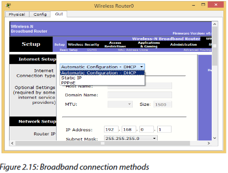
Step 5: Configure your broadband connection
On this model, you clicked the "Setup" menu and "Basic setup" sub menu. Again, your model may differ, and newer models may include a guided wizard that takes you through these steps.
Step 6: Configure your wireless network basics
If your router is connected to broadband and it is working successfully, we can setup the wireless networking configuration. On our sample router we clicked the "Wireless" sub menu.
Assign your wireless network a name, also known as Service Set Identifier (SSID). Choose a unique name in case there may be neighboring wireless routers nearby.

Step 7: Configure your wireless security
Most wireless network users will select one of four degrees of encryption security available in wireless hardware today.
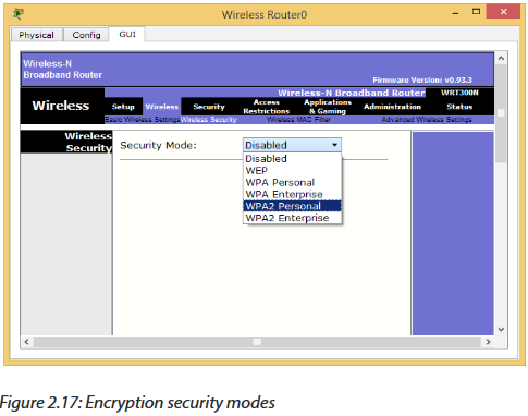
1. WEP: The oldest and least secure data encryption. All wireless gear supports WEP, though, it is useful when you need at least some kind of encryption to be compatible with older wireless hardware.
2. WPA: A more secure upgrade to WEP. Designed so that many older devices which included only WEP can be upgraded to support WPA.
3. WPA2: A significantly more secure upgrade to either WEP or WPA. Cannot upgrade older hardware to WPA2, but many new wireless devices support WPA2.
Note: At each step you must click on the “save Settings” button before you proceed with the next step
2.4.3.1 Router Operation Mode
Many of the routers offers different operation modes that you can use.
a. Wireless Router Mode
In wireless router/ IP sharing mode, the router connects to the Internet via PPPoE, DHCP, PPTP, L2TP, or Static IP and shares the wireless network to LAN clients or devices. Select this mode if you are a first-time user or you are not currently using any wired/wireless routers.
b.Repeater Mode
In Repeater mode, your router wirelessly connects to an existing wireless network to extend the wireless coverage. You will generally use repeaters or wireless extenders
when you have hard to reach places with your home Wi-Fi setup.
c. Access Point (AP) Mode
In Access Point (AP) mode, the router connects to a wireless router through an Ethernet cable to extend the wireless signal coverage to other network clients. This mode is best to be used in an office, hotel, and places where you only have wired network.
d.Media Bridge or Client Mode
With client mode or media bridge, it can connect to a wired device and works as a wireless adapter to receive wireless signal from your wireless network. The reason for this mode is that it can increase the speed of your wireless connection so that it matches the speed of the Ethernet connection.
2.4.3.2 Default gateway
A default gateway is used to allow devices in one network to communicate with devices in another network. If your computer, for example, is requesting an Internet webpage, the request first runs through your default gateway before exiting the local network to reach the Internet.An easier way to understand a default gateway might be to think of it as an intermediate device between the local network and the Internet.
a. Configuring the default gateway on a wireless router
Start packet tracer, add a wireless router and do the following:
-Click on wireless router and go to GUI tab.
-Set the Internet Connection type to Static IP.
-Configure the IP addressing according to the figure below.
-Scroll down and click on Save Settings.

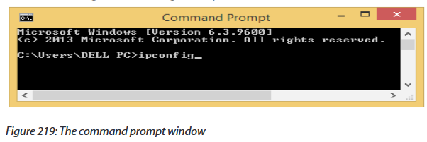
b.How to find your default gateway IP address
You might need to know the IP address of the default gateway if there is a network problem or if you need to make changes to your router.
-In Microsoft Windows, the IP address of a computer's default gateway can be accessed through Command Prompt with the ipconfig command, as well as through the Control Panel.
-The netstat and ip route commands are used on macOS and Linux for finding the default gateway address.

c. Configuring a default gateway on a desktop
-Open the control panel-Click on Network and Internet
-Click on Network and sharing center
-Click on adapter settings
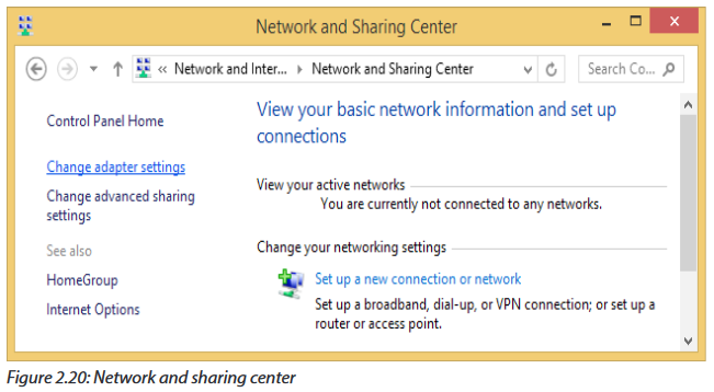
-Right click on wi-fi and choose properties

Key Unit Competency: To be able to identify computer network models, protocols and configure network devices
Introductory Activity
Look at figure 2.1 below and answer the following questions:
1. Describe what you see.
2. Are the above computers communicating? How and why?
3. In which case the communication may not be possible?
4. What type of network does the figure above represent?
5. How the Computers A and B are connected?
6. Is there any other way of connecting A, B and C
2.1 LAN architecture
Activity 2.1:
Visit your school computer lab and look at the existing Network and answer the followings questions:
1. Describe how computers are connected to the Network?
2. Determine the type of the logical or physical arrangement of network devices (nodes) in that network.
2.1.1 Definition of LAN Architecture?
A Local Area Network (LAN) architecture is the overall design of a computers network that interconnects computers within a limited area such as a residence, school, laboratory, university campus of office building. The LAN architecture consists of three levels: Physical, Media Access Control (MAC) and Logical Link Control (LLC).
•The LLC provides connection management, if needed.
•The Media Access Control (MAC) is a set of rules for accessing high speed physical links and for transferring data frames from one computer to another in a network.
•The Physical level deals mainly with actual transmission and reception of bits over the transmission medium.
2.1.2 Major Components of LANs
A LAN is made of the following main components:
-Hardware:
◊ Computers
◊ Network interface card (NIC) linked to physical address
◊ Media or Cables (Unshielded twisted pair, Coaxial cable, Optical fiber, Air for wireless)
◊ Hub, Switches, repeaters
-Access Methods: Rules that define how a computer puts data on and takes it from the network cable.
-Software: Programs to access and / or to manage the network.
2.1.3 Aspects of LAN architecture.
These aspects include:
-LAN’s physical topology: defines how the nodes of the network are physically connected
-LAN’s logical topology: how data is transmitted between nodes
-LAN’s MAC protocol: used for the physical identification of different devices within the network
2.1.4 Ethernet
Ethernet is a family of computer networking technologies commonly used in local area networks, metropolitan area networks and wide area networks. Ethernet cable is one of the most popular forms of network cable used in wired networks. They connect devices together within a local area network like PCs, routers and switches. A standard Ethernet network can transmit data at a rate up to 10 Megabits per second (10 Mbps). Ethernet uses CSMA/CD (Carrier Sense multiple Access with Collision Detection)
2.1.5 Carrier Sense Multiple Access with Collision Detection (CSMA/CD)
In a LAN, computers transmit data to each other. Normally, there is order to follow so that two computers can not send data at the same time while they are using the same route. When it happens that two computers send messages at the same time, there is what we call data collision. Therefore, a data collision occurs when two or more computers send data at the same time. When this happens, each computer stops data transmission and waits to resend it when the cable is free. Carrier Sense Multiple Access with Collision Detection (CSMA/CD) is a set of rules determining how network devices respond to a collision.
How does the CSMA/CD work?
Consider the following picture:
On the figure above, host A is trying to communicate with host B. Host A “senses” the wire and decides to send data. But, in the same time, host D sends its data to host C and the collision occurs. The sending devices (host A and host D) detect the collision and resend the data after a random period of time.
When a collision occurs on an Ethernet LAN, the following happens:
•A jam signal informs all devices that a collision occurred.
A signal sent by a device on an Ethernet network to indicate that a collision has occurred on the network is called a jam signal.
•The collision invokes a random back off algorithm (a set of rules which controls when each computer resend the data in order to assure that no more collision will happen again).
•Each device on the Ethernet segment stops transmitting for a short time until the timers expire.
•All hosts have equal priority to transmit after the timers have expired.
Application activity 2.1:
1. Realize a physical topology using devices like router, switches, Hubs, Ethernet cables and 4 computers available in your school computer lab as indicated in Fig. 2.2.
2. Describe how does the CSMA/CD enable the communication over Ethernet?
2.2 Cable Ethernet Standards
Activity 2.2:
Look around your school computer lab and answer the following question:Observe and describe the communication media (different types of Cables) available there.
2.2.1 Definition of standard
Standards provide guidelines to manufacturers, vendors, government agencies, and other service providers in guaranteeing national and international interoperability of data and telecommunications technology and processes. With Ethernet technologies, different types of standards have been so far used in networks.
The different Ethernet technologies used in wired networks to connect computers are given in the following table. The choice of one or another type depends on the size of networks and the quantity of data to exchange.
10BASE-F
10BASE-F is a generic term for the family of 10 Mbit/s Ethernet standards using fiber optic cable. In 10BASE-F, the 10 represents its maximum throughput of 10 Mbit/s, BASE indicates its use of base band transmission, and F indicates that it relies on medium of fiber-optic cable. In fact, there are at least three different kinds of 10BASE-F. All require two strands of 62.5/125 μm multimode fiber.One strand is used for data transmission and one strand is used for reception, making 10BASE-F a full-duplex technology.
The 10BASE-F variants include 10BASE-FL, 10BASE-FB and 10BASE-FP. Of these only 10BASE-FL experienced widespread use. All 10BASE-F variants deliver 10 Mbit/s over a fiber pair. These 10 Mbit/s standards have been largely replaced by faster Fast Ethernet, Gigabit Ethernet and 100 Gigabit Ethernet standards.
10BASE-FL
10BASE-FL is the most commonly used 10BASE-F specification of Ethernet over optical fiber. In 10BASE-FL, FL stands for fiber optic link. It replaces the original fiber-optic inter-repeater link (FOIRL) specification, but retains compatibility with FOIRL-based equipment. The maximum segment length supported is 2000 meters.When mixed with FOIRL equipment, maximum segment length is limited to FOIRL's 1000 meters.
Today, 10BASE-FL is rarely used in networking and has been replaced by the family of Fast Ethernet, Gigabit Ethernet and 100 Gigabit Ethernet standards.
10BASE-FB
The 10BASE-FB (10BASE-FiberBackbone) is a network segment used to bridge Ethernet hubs. Due to the synchronous operation of 10BASE-FB, delays normally associated with Ethernet repeaters are reduced, thus allowing segment distances to be extended without compromising the collision detection mechanism. The maximum allowable segment length for 10BASE-FB is 2000 meters.
10BASE-FP
10BASE-FP calls for a non-powered signal coupler capable of linking up to 33 devices, with each segment being up to 500m in length. This formed a star-type network centered on the signal coupler. There are no devices known to have implemented this standard.
2.2.1 Wireless network standards
Wireless LANs (WLANs) use radio frequencies (RFs) that are radiated into the air from an antenna that creates radio waves.
Because WLANs transmit over radio frequencies, they are regulated by the same types of laws used to govern things like AM/FM radios. It is the Federal Communications Commission (FCC) that regulates the use of wireless LAN devices, and the IEEE takes it from there and creates standards based on what frequencies the FCC releases for public use.
The wireless standards like the Ethernet standards are applied in different situations. The table below clearly describes each type.
2.2.3 Range, bandwidth and frequency
One characteristic that measures network performance is bandwidth. The bandwidth reflects the range of frequencies we need. However, the term can be used in two different contexts with two different measuring values: bandwidth in hertz and bandwidth in bits per second.
a. Bandwidth in Hertz
Bandwidth in hertz is the range of frequencies contained in a composite signal or the range of frequencies a channel can pass. For example, we can say the bandwidth of a subscriber telephone line is 4 kHz.
b.Bandwidth in Bits per Seconds
The term bandwidth can also refer to the number of bits per second that a channel, a link, or even a network can transmit per second. For example, one can say the bandwidth of a Fast Ethernet network is a maximum of 100 Mbps. This means that this network can send 100 Megabits per second.
2.2.3.1 Frequency and Network Range
The higher the frequency of a wireless signal, the shorter its range. 2.4 GHz wireless networks therefore cover a significantly larger range than 5 GHz networks. In particular, signals of 5 GHz frequencies do not penetrate solid objects nearly as well as do 2.4 GHz signals, limiting their reach inside homes.
Many older Wi-Fi devices do not contain 5 GHz radios and so must be connected to 2.4 GHz channels in any case.
2.2.3.2 Range, Bandwidth and Frequency
•The term ‘Bandwidth’ refers to the speed at which data is transferred over the wireless network (more bandwidth means faster downloading and uploading)
•The term ‘Range’ refers to the maximum distance from the router at which the network can be received (the greater the range, the further you can be from the router and still be connected).
•The term ‘Frequency’ refers to the number of waves that pass a fixed place in a given amount of time. So if the time it takes for a wave to pass is is 1/2 second, the frequency is 2 per second. If it takes 1/100 of an hour, the frequency is 100 per hour.
Usually frequency is measured in the hertz unit, named in honor of the 19th-century German physicist Heinrich Rudolf Hertz. The hertz measurement, abbreviated Hz, is the number of waves that pass by per second. For example, an "A" note on a violin string vibrates at about 440 Hz (440 vibrations per second).
2.2.3.3 Advantages and Disadvantages of the 2.4 GHz and the 5 GHz Wireless Networks
2.2.3.4 Token ring
Token ring or IEEE 802.5 is a network where all computers are connected in a circular fashion. The term token is used to describe a segment of information that is sent through that circle. When a computer on the network can decode that token, it receives data.
A Multistation Access Unit (MSAU) is a hub or concentrator that connects a group of computers ("nodes" in network terminology) to a token ring local area network. For example, eight computers might be connected to an MSAU in one office and that MSAU would be connected to an MSAU in another office that served eight other computers. In turn, that MSAU could be connected to another MSAU in another office, which would be connected back to the first MSAU. Such a physical configuration is called a star topology. However, the logical configuration is a ring topology because every message passes through every computer one at a time, each passing it on to the next in a continuing circle.
Application activity 2.2:
Your school has classrooms, computer labs and the staff room located in three different buildings as indicated in the figure below:
Questions:
1. Which kind of technology can you propose to connect computers in the 3 buildings. Explain you choice.
2. If you choose to install a wireless network within this school, in which building would you place the wireless device which serves the whole school? Explain.
3. What type of Ethernet cable would you use if you are requested to interconnect those three buildings? Explain.
2.3 Fiber Distributed Data Interface (FDDI)
2.3.1 Definition
The Fiber Distributed Data Interface (FDDI) is a standard developed by the American National Standards Institute (ANSI) for transmitting data on optical fiber cables. FDDI supports transmission rates of 100 megabits per second on token-passing networks.
FDDI provides high-speed network backbones that can be used to connect and extend LANs.
2.3.2 Advantages of FDDI
The Fiber Distributed Data Interface allows the transmission of very large volumes of data over large distances. It provides high bandwidth.
2.3.3 Disadvantages
The Fiber Distributed Data Interface (FDDI) is an expensive technology to set up because the network devices require a special network card and also the required fiber optic cabling is expensive than twisted-pair cable. Because most Fiber Distributed Data Interface (FDDI) installations use a redundant second ring, more cabling is required.
2.3.4 Fiber Optic cables
A fiber optic cable is a glass or plastic strand that transmits information using light and is made up of one or more optical fibers enclosed together in a sheath or jacket. It has the following properties:
•Not affected by electromagnetic or radio frequency interference.
•All signals are converted to light pulses to enter the cable, and converted back into electrical signals when they leave it.
•Signals are clearer, can go farther, and have greater bandwidth than with copper cable.
•Signal can travel several miles or kilometers before the signal needs to be regenerated.
•Usually more expensive to use than copper cabling and the connectors are more costly and harder to assemble.
•Common connectors for fiber-optic networks are SC, ST, and LC. These three types of fiber optic connectors are half-duplex, which allows data to flow in only one direction.
Therefore, two cables are needed.
a. Types of fiber optic
There are three types of fiber optic cable commonly used: single mode, multimode and plastic optical fiber (POF).
1. Single-mode: Cable that has a very thin core. It is harder to make, uses lasers as a light source, and can transmit signals dozens of kilometers with ease.
2. Multimode: Cable that has a thicker core than single-mode cable. It is easier to make, can use simpler light sources (LEDs), and works well over distances of a few kilometers or less.
3. Plastic optical fiber (POF):Transparent glass or plastic fibers which allow light to be guided from one end to the other with minimal loss.
The Fiber optic technologies are summarized in the following table.
Application activity 2.3:
4. Discuss the advantages and disadvantages of FDDI within a Local Area Network.
5. Referring to the figure on learning activity 2.3, what type of fiber optic cable would you recommend for the core and distribution layers? Explain.
2.4 Network devices
Activity 2.4.
In groups, look at the devices given below and answer the questions:
6. Describe the role of each one within a Local Area Network.
7. Explain how you can make a Local Area Network using the following devices?
There are many networking devices: NIC cards, Repeaters, HUB, Bridges, Switches and Router
2.4.1 Wireless LAN cards (Network adapters)
Also called Network Interface Cards (NICs), they are connectivity devices enabling a desktop, server, printer, or other node to receive and transmit data over the network media
a. Types of Wireless Network Interface Cards (NICs)
NICs come in a variety of types depending on:
-The access method (for example, Ethernet versus Token Ring)
-Network transmission speed (for example, 100 Mbps versus 1 Gbps)
-Connector interfaces (for example, RJ-45 versus SC)
-Type of compatible motherboard or device (for example, PCI)
-Manufacturer (popular NIC manufacturers include 3Com, Adaptec, D
-Link, IBM, Intel,
-Kingston, Linksys, and so on)
b.Wireless NIC card installation and configuration
-Refer to the card manufacturer's quick
-start guide. Alternatively, you can also run the software installation program on the CD which comes with the PCI card and observe the steps to install it.
-Shut down the PC.
-Remove the cover.
-Locate an available PCI slot and remove the corresponding slot cover from the back of the PC.
-Carefully route the antenna through the open slot in the back of the PC, insert the card in the slot, and secure it. Replace the cover.
-Power up the PC. It should recognize and enable the new hardware.
c. Wireless NIC card Driver installation through the Device Manager
Step 1: Right-click on Computer (or PC) to select Manage.
Step 2: On the left, select Device Manager to bring it up on the right.
Step 3: Right click on the unknown adapter to Update Driver Software.
Step 4: Click to Search automatically for updated driver software.
Step 5: Wait until the download process is successfully completed.
Step 6: Click on Save Settings or OK to apply the change.Confirmation of a successful Driver installation is achieved when the model of your adapter is labeled and listed in the Network adapters group of the Device Manager.
2.4.2 Routers and Access points
A wireless router is a device that performs the functions of a router and also includes the functions of a wireless access point. It is used to provide access to the Internet or a private computer network. Routers operate at the Network layer (Layer 3) of the OSI Model.
The Wireless access points (APs or WAPs) are networking devices that allow wireless Wi-Fi devices to connect to a wired network.
2.4.3 Configuring a wireless router
Step 1: Get to know your wireless router
•A power input jack one.
•One or more wired Ethernet jacks (often labeled 1, 2, 3, 4) for computers on your network which don't have wireless ability.
•One Ethernet jack for your broadband connection, often labeled “WAN” or “Internet.”
•A reset button. to
Step 2: Connect your router a wired PC for initial setup
Step 3: Open web browser and connect to wireless router administration INTERFACE
To connect to your router, you need to know its default IP address and connect your browser to http://routeripaddress. For example, if you own a Linksys brand wireless router, its default IP address is 192.168.1.1, and therefore you open your browser to the URL http://192.168.1.1.
Most wireless routers also require you to log in to access configuration pages. Your router includes a manual or a "quick setup" guide which details both its default IP address and default login.
Step 4: Determine your broadband type
There are three common broadband connection methods:
•DHCP Dynamic IP: Basic network parameters are automatically assigned to your router by the broadband modem.
•PPPoE: Requires you to supply a username and password provided to you by your ISP.
•Static IP: Your broadband provider would have supplied you with a set of numeric addresses you need to connect to the network, as they are not assigned automatically.
Step 5: Configure your broadband connection
On this model, you clicked the "Setup" menu and "Basic setup" sub menu. Again, your model may differ, and newer models may include a guided wizard that takes you through these steps.
Step 6: Configure your wireless network basics
If your router is connected to broadband and it is working successfully, we can setup the wireless networking configuration. On our sample router we clicked the "Wireless" sub menu.
Assign your wireless network a name, also known as Service Set Identifier (SSID). Choose a unique name in case there may be neighboring wireless routers nearby.
Step 7: Configure your wireless security
Most wireless network users will select one of four degrees of encryption security available in wireless hardware today.
1. WEP: The oldest and least secure data encryption. All wireless gear supports WEP, though, it is useful when you need at least some kind of encryption to be compatible with older wireless hardware.
2. WPA: A more secure upgrade to WEP. Designed so that many older devices which included only WEP can be upgraded to support WPA.
3. WPA2: A significantly more secure upgrade to either WEP or WPA. Cannot upgrade older hardware to WPA2, but many new wireless devices support WPA2.
Note: At each step you must click on the “save Settings” button before you proceed with the next step
2.4.3.1 Router Operation Mode
Many of the routers offers different operation modes that you can use.
a. Wireless Router Mode
In wireless router/ IP sharing mode, the router connects to the Internet via PPPoE, DHCP, PPTP, L2TP, or Static IP and shares the wireless network to LAN clients or devices. Select this mode if you are a first-time user or you are not currently using any wired/wireless routers.
b.Repeater Mode
In Repeater mode, your router wirelessly connects to an existing wireless network to extend the wireless coverage. You will generally use repeaters or wireless extenders
when you have hard to reach places with your home Wi-Fi setup.
c. Access Point (AP) Mode
In Access Point (AP) mode, the router connects to a wireless router through an Ethernet cable to extend the wireless signal coverage to other network clients. This mode is best to be used in an office, hotel, and places where you only have wired network.
d.Media Bridge or Client Mode
With client mode or media bridge, it can connect to a wired device and works as a wireless adapter to receive wireless signal from your wireless network. The reason for this mode is that it can increase the speed of your wireless connection so that it matches the speed of the Ethernet connection.
2.4.3.2 Default gateway
A default gateway is used to allow devices in one network to communicate with devices in another network. If your computer, for example, is requesting an Internet webpage, the request first runs through your default gateway before exiting the local network to reach the Internet.An easier way to understand a default gateway might be to think of it as an intermediate device between the local network and the Internet.
a. Configuring the default gateway on a wireless router
Start packet tracer, add a wireless router and do the following:
-Click on wireless router and go to GUI tab.
-Set the Internet Connection type to Static IP.
-Configure the IP addressing according to the figure below.
-Scroll down and click on Save Settings.
b.How to find your default gateway IP address
You might need to know the IP address of the default gateway if there is a network problem or if you need to make changes to your router.
-In Microsoft Windows, the IP address of a computer's default gateway can be accessed through Command Prompt with the ipconfig command, as well as through the Control Panel.
-The netstat and ip route commands are used on macOS and Linux for finding the default gateway address.
c. Configuring a default gateway on a desktop
-Open the control panel-Click on Network and Internet
-Click on Network and sharing center
-Click on adapter settings
-Right click on wi-fi and choose properties
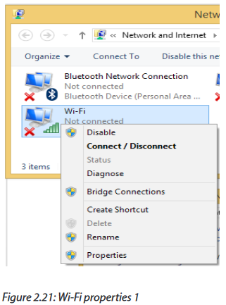
-Choose Internet Protocol Version 4 (TCP/IPv4) and click on properties

-Enter IP address as follows and then click on OK:

2.4.4 Public and private IP2.
4.4.1 Public IP addresses
A public IP address is the one that your ISP (Internet Service Provider) provides to identify your home network to the outside world. It is an IP address that is unique throughout the entire Internet. A public IP address is worldwide unique, and can only be assigned to a unique device
Depending on your service, you might have an IP address that never changes (a fixed or static IP address). But most ISPs provide an IP address that can change from time to time (a dynamic IP address)
Example: Web and email servers directly accessible from the Internet use public IP addresses.
2.4.4.2 Private IP addresses
A private IP address provides unique identification for devices that are within your Local Area Network, such as your computer, your smartphones, and so on.If every device on every network had to have real routable public IP addresses, we would have run out of IP addresses to hand out years ago. Private IP addresses are used for the following reasons:
-To create addresses that cannot be routed through the public Internet
-To conserve public addresses
Examples:
-Computers, tablets and smartphones within an organization are usually assigned private IP addresses.
-A network printer residing in your school computer lab is assigned a private address so that only users within computer lab can print to your local printer.
-Notice that IP addresses, public or private, are assigned to devices according to network classes. The most used classes are A, B and C. They differ according to the number of networks and hence to the number of IP addresses in one network. From A to C, the number of possible networks increase while number of available IP addresses in a network reduces.

2.4.5 Configuring a wireless Access Point
The physical setup for a wireless access point is pretty simple: you take it out of the box, put it on a shelf or on top of a bookcase near a network jack and a power outlet, plug in the power cable, and plug in the network cable.
To get to the configuration page for the access point, you need to know the access point’s IP address. Then, you just type that address into the address bar of a browser from any computer on the network.
For example to configure TP-Link TL-WA701ND Access Point you will follow the following steps:
Step 1: Power the TP-Link TL-WA701ND using the barrel jack or PoE (Power-over-Ethernet) injector, and connect a computer to the access point using an Ethernet cable (if using the PoE injector, connect the LAN port to your computer, and the POE port to the access point).
Step 2: Ensure all wireless interfaces are disabled on the computer (such as WiFi and Bluetooth) and that DHCP is enabled on the Ethernet interface. Open a web browser and access the TL-WA701ND by entering 192.168.0.254 into the address bar.
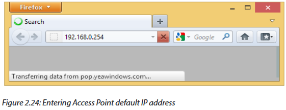
Step 3: Log in using username admin and password admin
Step 4: The Quick Setup wizard will load in the browser. Click Next to start the configuration process.

Step 5: Select Client from the list of operating modes. Click Next.
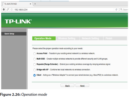
Step 6: Click Survey to scan for a list of available wireless access points. Alternatively, skip to step 8 and manually enter information.

Step 7: From the list of available WiFi networks, select the network to use by clicking Connect to the far right. Make sure the network has a good connection by checking the signal strength. The higher the number, the stronger the connection.
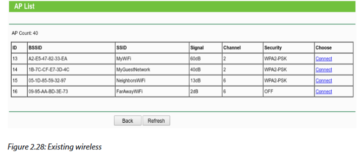
Step 8: Once the Connect option is clicked, these fields will automatically fill in. Alternatively, enter the Wireless Name (SSID) and Wireless Security Mode and Wireless Password. The wireless security settings will need to be manually entered for any password protected WiFi network. Click Next.

Step 9: The default values are typically fine for these settings. If needed, obtain the correct settings from the network administrator. Be sure to make a note/take a screenshot of the IP address set in this step, as it will replace the original fallback IP address. When the correct settings have been applied, click Next.
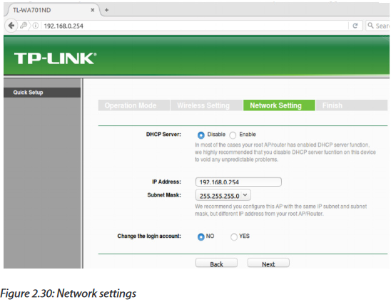
Step 10: Make a note or take a screenshot of the applied settings if desired, then click Save.

Step 11: The device will reboot. The configuration page will likely not load; try loading a web-page (e.g. http://www.irembo.gov.rw) while the TP-Link Access Point is connected to the computer to see if there is Internet connectivity.
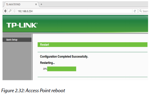
Step 12: Troubleshooting
•The TP-Link TP-WA701ND does not have any LEDs illuminated
* Ensure the access point has power either directly to the barrel jack on the back, or via the POE injector’s POE Ethernet port. The POE injector requires power via barrel jack.
* Verify the ON/OFF button next to the access point’s Ethernet port is depressed in the ON position.
•I cannot access the device configuration page.
* The TP-Link WA701ND has a default fallback IP address of 192.168.0.254. To access the device configuration pages, connect a computer directly via an Ethernet cable, configure the computer to use an IPv4 address in the same range (for example, 192.168.0.100), open a web browser, and enter the fallback IP address of 192.168.0.254 in the address bar. If you changed the IP address on the Network Setting page during configuration step 9, use that IP address instead.
•I cannot access the device at all (lost credentials, major configuration issue, etc)
* The TP-Link TL-WA701ND has a recessed reset button located on the back of the device. This button is closest to the antenna, and a pin or paperclip is needed to press it. Hold the button down for 8+ seconds. All of the LEDs should turn off and back on; after this the initial configuration steps can be used to gain access. Note that this will reset all device settings to the factory default.
2.4.5 How to connect to the Internet through your wireless access point?
a. Connecting to Internet through the control panel
-Open the windows control panel, and then click network and Internet.
-The Network and Internet window appears.

-Click network and sharing center.
-The Network and Sharing Center window appears.
-Click set up a new connection or network.
 -Set up a Connection or Network window appears.-Click Manually connect to a wireless network
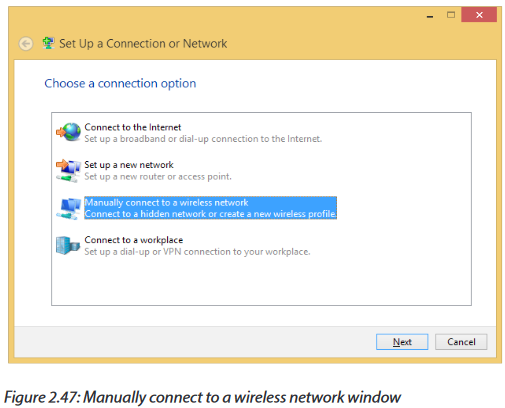
-Click Manually connect to a wireless network
-Enter your wireless name in the Network name textbox, for example in our case we want to connect to “Wireless AP”
-Choose WPA2
-Personal for security type
-Choose AES for encryption type
-Type wireless key in the security key textbox
-Click next
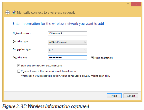
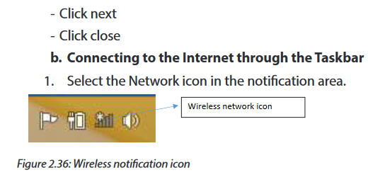
2. In the list of networks, choose the network that you want to connect to, and then select Connect.
3. Type the security key (often called the password).
4. Follow additional instructions if there are any.
2.4.7 Wireless Access Point vs Router
The Wireless Access Points (AP) and routers play the similar role but they have some differences. They all connect different networks. A router often has an Access Point built-in, but a standalone Access Point can’t be a router. An AP can be compared to a modem which is limited in its functionality on managing multiple devices or controlling an entire network with many devices.Routers on the other hand can manage an entire home or small business giving network capability to many computers and devices simultaneously.
2.4.7.1 Wireless Access Point Functions
APs give wireless network ability to any device that only has a hard-wired connection. It is done by plugging in an Ethernet cable and the AP would then communicate with WiFi devices and giving them network access. .For example a printer that has no built-in wireless can have a access point added which will give it wireless ability.
While current routers have built-in WiFi and play many roles including being an AP, many don’t use dedicated AP.APs are still used in many networks and they are used to help with WiFi dead spots and extending a wireless network.
An AP can be added in locations that have bad wireless network ability and give good coverage throughout a home or business.
2.4.7.2 Router Functions
From the above section, a router is a network device that can transfer data wirelessly or wired. It forwards data packets to the desired device and control LAN (local Area Networks) or WAN (Wide Area Networks) networks
2.4.7 SSID and encryption
2.4.7.1 SSID and Wireless Networking
An SSID (Service Set Identifier) is the primary name associated with an 802.11 Wireless Local Area Network (WLAN) including home networks and public hotspots. Client devices use this name to identify and join wireless networks.
When you right click on the icon of wireless network in the Task Bar (Bottom Right of the computer’s screen), the displayed list of names of different networks are the SSID that are covered now or have been used in past.
On home Wi-Fi networks, a broadband router or broadband modem stores the SSID but allows administrators to change it. Routers can broadcast this name to help wireless clients find the network. Router manufacturers set a default SSID for the Wi-Fi unit, such as Linksys, xfinitywifi, NETGEAR, dlink or just default. However, since the SSID can be changed, not all wireless networks have a standard name like that.
2.4.7.2 Wireless fundamentals: Encryption and authentication
Wireless encryption and authentication help users to make an educated decision on what type of security to implement into their wireless network. There exist different types of encryption and authentication. For example, CISCO Meraki is using the following:
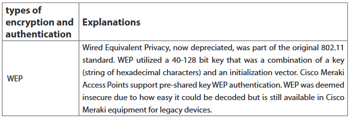


Application activity 2.4:
A. Look around your school computer lab and do the following:
•Uninstall and reinstall wireless adapters into your desktops
•Switch on your computers and check whether wireless drivers are installed.
•Using your computers, check for available wireless signal?
•Login into your wireless router and change its SSID to “NetworkingLab”.
•What is the IP address of your computer?
•Discuss the advantages of protecting your wireless network with a password?
B. Using one smart phone, setup a computer network made of your laptops. Describe how to connect to that network. What is the name of the network? Change that name and set up a new password.
2.5 computer Network Protocols
Activity 2.5:
The school computer lab has 20 computers connected to the Local Area Network and Internet. Using his computer, the teacher wishes to get a copy of 40 MB document in all computers but he does not have any storage devices to facilitate the task. In groups, discuss possible ways to obtain this document in all computers in laboratory. Apply your proposed solutions.
2.5.1 Definition
A network protocol defines rules and conventions for communication between network devices. Network protocols include mechanisms for devices to identify and make connections with each other, as well as formatting rules that specify how data is packaged into messages sent and received.
Network protocols are grouped such that each one relies on the protocols that underlie it sometimes referred to as a protocol stack. The key network protocols are the following:
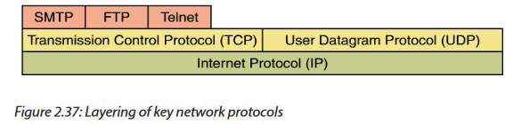
2.5.1 Most used protocols
The most used protocols with their descriptions are given in the following table.
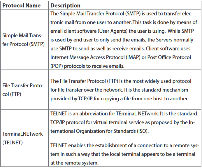
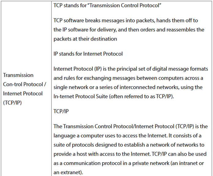
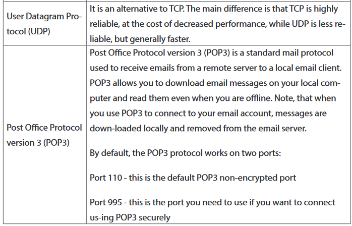

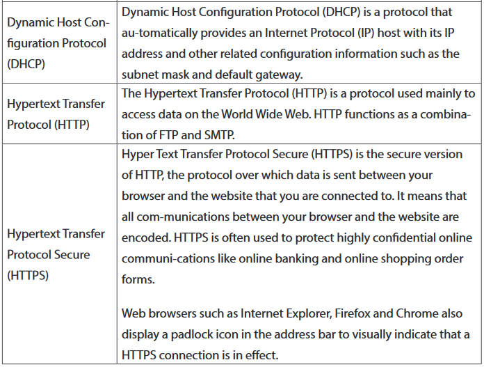
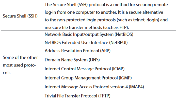
Application activity 2.5:
1. Discuss the role of protocols in computer communication?
2. Search on Internet a free application called FileZilla Client and FileZilla Server using FTP to get access remotely to documents on another computer in the school computer lab. Copy to /from any document between the 2 computers.
2.6 OSI model
Activity 2.6:
Fill in the blanks with the appropriate device between hub, switch and router.
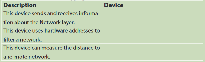
2.6.1 Definition
Open System Interconnect (OSI) is an open standard for all communication systems. OSI model is established by International Standard Organization (ISO). It is a general-purpose model for discussing or describing how computers communicate with one another over a network. Its seven-layered approach to data transmission divides the many operations up into specific related groups of actions at each layer
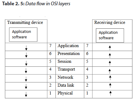
In the OSI model, data flows down the transmit layers, over the physical link, and then up through the receive layers. The transmitting computer software gives the data to be transmitted to the applications layer, where it is processed and passed from layer to layer down the stack with each layer performing its designated functions. The data is then transmitted over the physical layer of the network until the destination computer or another device receives it. At this point the data is passed up through the layers again, each layer performing its assigned operations until the data is used by the receiving computer’s software. The roles of OSI model layers are:

a. The Application Layer
The application layer enables the user, whether human or software, to access the network. It provides user interfaces and support for services such as domain name service (DNS), file transfer protocol (FTP), hypertext transfer protocol (HTTP), Internet message access protocol (IMAP), post office protocol (POP), simple mail transfer protocol (SMTP), Telenet, and terminal emulation. Devices used in this layer are Gateways, Firewalls, and all end devices like PC’s, Phones, and Servers.
b.The Presentation Layer
It presents data to the Application layer and is responsible for data translation and code formatting.
The presentation layer is concerned with the syntax and semantics of the information exchanged between two systems.
Specific responsibilities of the presentation layer include the following:
•Translation
•Encryption
•Compression
Devices which operate at this layer are Gateways, Firewalls and PC’s.
c. The Session Layer
The Session layer is responsible for setting up, managing, and then destroying down sessions between Presentation layer entities. This layer also provides dialogue control between devices, or nodes.
It coordinates communication between systems and serves to organize their communication by offering three different modes of communication: simplex, half duplex, and full duplex.
Specific responsibilities of the session layer include the following:
•Dialog control
•Synchronization
The devices used at this layer are Gateways, Firewalls, and PC’s.
d.The Transport Layer
The Transport layer segments and reassembles data into a data stream. Services located in the transport layer segment and reassemble data from upper-layer applications and unite it onto the same data stream. They provide end-to-end data transport services and can establish a logical connection between the sending host and destination host on an internetwork. At this layer we find devices like Gateways and Firewalls.
e. The Network Layer
The Network layer manages device addressing, tracks the location of devices on the network, and determines the best way to move data, which means that the Network layer must transport traffic between devices that are not locally attached. Routers (layer 3 devices) are specified at the Network layer and provide the routing services within an Internetwork.
The network layer is responsible for the delivery of individual packets from the source host to the destination host.
Two activities are performed:
•Logical addressing: IP addressing
•Routing: Source to destination transmission between networks
f. The Data Link Layer
The Data Link layer formats the message into pieces, each called a data frame, and adds a customized header containing the hardware destination and source address. This added information forms a sort of capsule that surrounds the original message.
To allow a host to send packets to individual hosts on a local network as well as transmit packets between routers, the Data Link layer uses hardware addressing.
Switches and bridges work at the Data Link layer and filter the network using hardware (MAC) addresses.
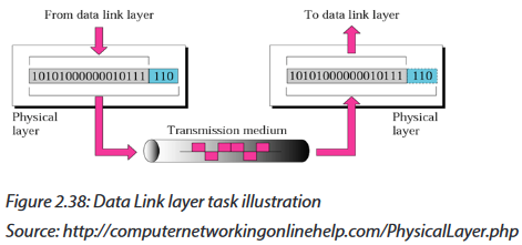
g.The Physical Layer
Finally arriving at the bottom, the Physical layer does two things: It sends bits and receives bits. Bits come only in values of 1 or 0. The Physical layer communicates directly with the various types of actual communication media.
The Physical layer specifies the electrical, mechanical, procedural, and functional requirements for activating, maintaining, and deactivating a physical link between end systems. This layer is also where you identify the interface between the data terminal equipment (DTE) and the data communication equipment (DCE). Devices like Hubs, Repeaters, Cables, and Fibers operate at this layer.

Notice that the following network devices operate on all seven layers of the OSI model:
-Network management stations (NMSs)
-Web and application servers
-Gateways (not default gateways)
-Network hosts
2.6.2 Advantages of using the OSI layered model
1. It divides the network communication process into smaller and simpler components, thus aiding component development, design, and troubleshooting.
2. It allows multiple-vendor development through standardization of network components.
3. It encourages industry standardization by defining what functions occur at each layer of the model.
4. It allows various types of network hardware and software to communicate.
5. It prevents changes in one layer from affecting other layers, so it does not hamper hardware or software development.
Application activity:
1. Which layer of the OSI model creates a virtual link between hosts before transmitting data?
2. What is the main reason of the creation of OSI model?
3. Describe each one of the 7 layers of the OSI model.
4. Which layer is responsible for converting data packets from the Data Link layer into electrical signals?
5. At which layer is routing implemented, enabling connections and path selection between two end systems?
6. Which layer defines how data is formatted, presented, encoded, and converted for use on the network?
7. Which layer is responsible for creating, managing, and terminating sessions between applications?
8. Search on Internet and propose the format of a packet sent between 2 computers through the
2.7 TCP/IP model
Learning activity 2.7:
One teacher at your school wants to send a 50MB file to students’ emails but when he tries to attach it the email server rejects because of the size limit. It says that it cannot upload files larger than 20MB.
1. What are other alternative to share this file?
2.7.1 Introduction
The TCP/IP protocol suite was developed prior to the OSI model. Therefore, the layers in the TCP/IP protocol suite do not exactly match those in the OSI model. TCP/IP model is the combination of TCP as well as IP models. This model ensures that data received is same as the data sent, and the data bytes are received in sequence. This model mainly defines how data should be sent (by sender) and received (by receiver). Most common examples of applications using this model include the email, media streaming, or World Wide Web (WWW). Presentation and session layers OSI model are not there in TCP/IP model.
TCP/IP model comprises 4 layers that are as follows:

1. Application Layer
Application layer is the top most layer of four layers TCP/IP model. Application layer is present on the top of the Transport layer. Application layer defines TCP/IP application protocols and how host programs interface with Transport layer services to use the network.
It groups the functions of OSI Application, Presentation and Session Layers. It includes protocols like:
-The Hypertext Transfer Protocol (HTTP) is used to transfer files that make up the Web pages of the World Wide Web.
-The File Transfer Protocol (FTP) is used for interactive file transfer.
-The Simple Mail Transfer Protocol (SMTP) is used for the transfer of mail messages and attachments.
-Telnet, a terminal emulation protocol, is used for logging on remotely to network hosts.
2. Transport layer
Transport Layer (also known as the Host-to-Host Transport layer) is the third layer of the four layer TCP/IP model. The position of the Transport layer is between Application layer and Internet layer. The purpose of Transport layer is to permit devices on the source and destination hosts to carry on a conversation. Transport layer defines the level of service and status of the connection used when transporting data. It is responsible for providing the Application layer with session and datagram communication services.
The core protocols of the Transport layer are Transmission Control Protocol (TCP) and the User Datagram Protocol (UDP).
-TCP provides a one-to-one, connection-oriented, reliable communications service. TCP is responsible for the establishment of a TCP connection, the sequencing and acknowledgment of packets sent, and the recovery of packets lost during transmission.
-UDP provides a one-to-one or one-to-many, connectionless, unreliable communications service. UDP is used when the amount of data to be transferred is small (such as the data that would fit into a single packet).The Transport layer encompasses the responsibilities of the OSI Transport layer and some of the responsibilities of the OSI Session layer.
3. Internet layer
The Internet layer is responsible for addressing, packaging, and routing functions. The core protocols of the Internet layer are IP, ARP, ICMP, and IGMP.
-The Internet Protocol (IP) is a routable protocol responsible for IP addressing, routing, and the fragmentation and reassembly of packets.
-The Address Resolution Protocol (ARP) is responsible for the resolution of the Internet layer address to the Network Interface layer address such as a hardware address.
-The Internet Control Message Protocol (ICMP) is responsible for providing diagnostic functions and reporting errors due to the unsuccessful delivery of IP packets.
-The Internet Group Management Protocol (IGMP) is responsible for the management of IP multicast groups.The Internet layer is analogous to the Network layer of the OSI model.
4. Network Access Layer
This layer basically controls hardware devices and media that make up the network. Its tasks include routing of data, sending it over the network, verifying the data format, and converting the signs from analog to the digital format. TCP/IP can be used to connect differing network types. These include LAN technologies such as Ethernet and Token Ring and WAN technologies such as X.25 and Frame Relay.
The Network Interface layer encompasses the Data Link and Physical layers of the OSI model.
2.7.1 Summary of network models
The 2 network models do realize the same job of sending data between different networks. By comparing OSI and TCP/IP models, there is a difference because the number of layers differs. However, some layers like application in TCP/IP do the job done by many layers in OSI models. For example Application layer and Network layer in TCP/IP combine the role of many layers.
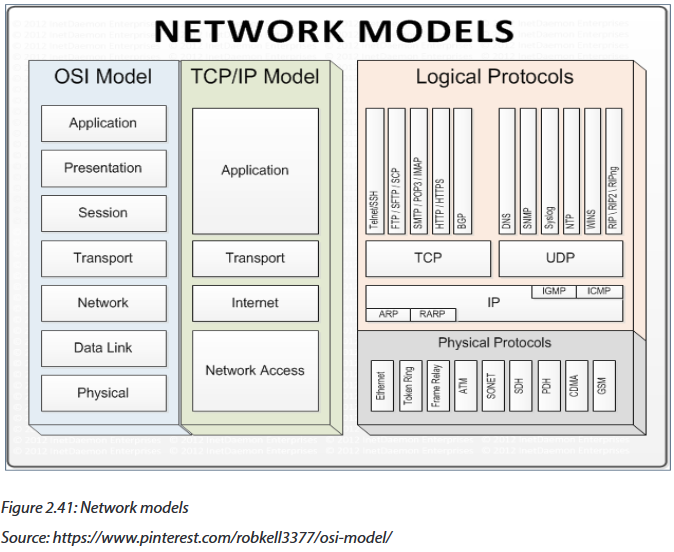
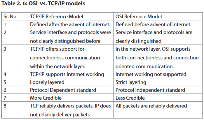
Application activity 2.7:
1. Which of the following are layers in the TCP/IP model? (Choose three.)
a. Application
b. Session
c. Transport
d. Internet
e. Data Link
f. Physical
2. What layer in the TCP/IP stack is equivalent to the Transport layer of the OSI model?
a. Application
b. Host-to-Host
c. Internet
d. Network Access
3. Using a figure, describe TCP/IP and OSI network models with their associated protocols.
4. Describe the purpose and basic operation of the protocols in the OSI and TCP models.
2.7.1 Network switching
Learning activity 2.8:
Look at the following two network designs represented by figure A and B and answer questions:
5. Describe what you see.
6. What is the difference between these two designs?
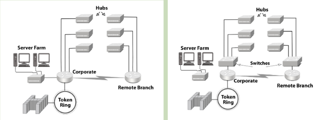
2.8.1 Definition
Switching is a process to forward packets coming in from one port to a port leading towards the destination. When data comes on a port it is called ingress, and when data leaves a port or goes out it is called egress.
A switched network consists of a series of interlinked nodes, called switches. In a switched network, some of these nodes are connected to the end systems (computers or telephones, for example). Others are used only for routing. The Figure below shows a switched network.
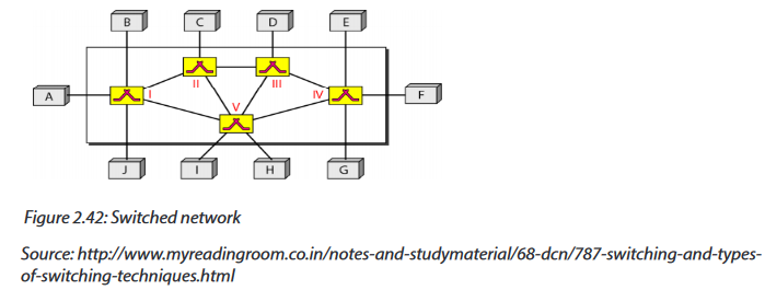
The end systems (communicating devices) are labeled A, B, C, D, and so on, and the switches are labeled I, II, III, IV, and V. Each switch is connected to multiple links.
The advantages of switches are as follows:
-Switches increase available network bandwidth
-Switches reduce the workload on individual computers
-Switches increase network performance
-Networks that include switches experience fewer frame collisions because switches create collision domains for each connection (a process called micro segmentation)
-Switches connect directly to workstations.
2.8.2 Switching methods
The classification of switched networks is given by the figure below.

2.8.2.1 Circuit-Switched Networks
Circuit switching is a switching method in which a dedicated communication path in physical form between two stations within a network is established, maintained and terminated for each communication session. Applications which use circuit switching may have to go through three phases:
•Establish a circuit
•Transfer the data
•Disconnect the circuit
2.8.2.2 Packet Switched Networks
In packet switched data networks all data to be transmitted is first broken down into smaller chunks called packets. The switching information is added in the header of each packet and transmitted independently.
It is easier for intermediate networking devices to store small size packets and they do not take much resources either on carrier path or in the internal memory of switches.

Packet switching can be done through the following technologies:
g. Datagram networks
Packets are treated independently and may take different routes. Datagram is better if numbers of packets are not very large.
h. Virtual circuit networks
In virtual circuit, a logical path is setup prior the transmission and therefore, no routing decision is to make which ensure that packet are forwarded more quickly than datagram. The logical path between destination and source also assure the sequencing of packet and better error control. However, virtual circuit is less reliable because Interruption in a switching node loses all circuit through that node.
2.8.2.3 Message switching
In message switching, if a station wishes to send a message to another station, it first adds the destination address to the message. Message switching does not establish a dedicated path between the two communicating devices i.e. no direct link is established between sender and receiver. Each message is treated as an independent unit.
Consider a connection between the users (A and D) in the figure below (i.e. A and D) is represented by a series of links (AB, BC, and CD).
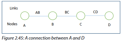
For example, when an email message is sent from A to D, it first passes over a local connection (AB). It is then passed at some later time to C (via link BC), and from there to the destination (via link CD). At each message switch, the received message is stored, and a connection is subsequently made to deliver the message to the neighboring message switch.
Application activity 2.8
1. How does the message switching differ from circuit switching?
2. Explain the technologies used in packet switching.
END UNIT ASSESSMENT ACTIVITIES
1. Your school has acquired 60 computers from the Rwanda Education Board (REB) and wishes to distribute them as follows:
- Administration: 3 computers
- Staff room: 7 computers
- Computer lab for students in Ordinary level: 30 computers
- Computer lab for students in Advanced level: 20 computers
a. List and describe specifications of all materials needed to setup 2 wireless LANs within the school.
b. Is it possible to secure those wireless networks?
c. Indicate the type of wireless security to be used.
2. Discuss the advantages of Fiber optic cables within a LAN.
3. Why routers and switches do not operate at the same OSI reference model layer?
4. What are the common steps in configuring both wireless router and access points?
5. Is it possible to change the default gateway of your computer? Explain.
6. When and how both public and private IP addresses are used within the same network?
7. Describe the purpose and basic operation of the protocols in the OSI and TCP models.
8. What are the advantages of using OSI layered model?
9. Discuss the importance of switches within a LAN.
UNIT 3 :NETWORKING PROJECT
UNIT 3: NETWORKING PROJECT
Key Unit Competency:To be able to build a computer wired and wireless network
INTRODUCTORY ACTIVITYObserve the following figure
Figure: 3.1: Networking tools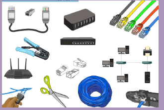
Observe the figure above and answer the following questions
1. List all the medium in the figure above
2. Using two telephones or two laptops state different steps which can help sharing films via Bluetooth technology.
3. Choose the different tools which can help in crossover Network cable making4. Describe all network tools available in the school computer Lab and in the figure 3.1
3.1 Build Peer to Peer network
Project I: Preparing Ethernet cables and devices
P2P Project 3.1. A
1) You are given 10 computers, UTP cables, RG-45, crimping tools, switch/ hub
a. Arrange the tools and devices required to build P2P network
b. Prepare cables required to build P2P network
c. Test each cable if they are properly working.
d. Connect cables to different devices.
e. How will you dispose your useless materials?
f. To avoid the loss of many materials which are costly, what measures would you
take?
Observation: If you have a green light, the connection is successful; if the
color is Red, the connection is failed, please revise you cabling. If tried twicewithout success, please call the teacher/Lab technician.
3.1.1 Tools required building P2P Network
This practice has crucial important as when files are shared to the network will reduce
the cost of printout papers as one document can be shared by many users who
stands in the same P2P network or when sharing printer to the same P2P network,
all users can enjoy printing without taking time in installing setup to all computers
in the same work group.
In order to build peer to peer network we need several equipment discussed in
previous network classes, the maximum number of computer to build a P2P network
is 10, transmission media needed is UTP cables. We use crossover to connect the
same devices (hub to hub, computer to computer, router to router, and switch to
switch) and straight through cable to connect different devices (Computer to switch,
computer to hub). We use star topology where we need Switch/hub as the central
devices. To build a P2P network of 2 computers we need only two computers and
Ethernet cable (Strait through cable), for P2P network of more than 2 computers we
need computers, Ethernet cables (Crossover and Straight through) and Switch/hub.
3.1.2 Process to build P2P network
We are going to build a peer to peer network for small office or home office.
Step 1: Make sure all computers are turned off, organized and arranged.
In this practice we need to arrange 10 computers which is the maximum number of
computer allowed in P2P network.Step 2: Install central devices (Switch or hub).
Step 3: Connect each end of the UTP CAT 6 straight through cables to connect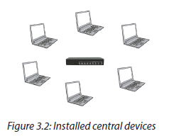
computers to Switch/ Hub.
When connecting devices, UTP CAT 6 straight through cable is required to connect
the same devices (Computer to computer) and UTP CAT 6 crossover cable to connect
different devices (Switch to computer), depending on number of devices we have in
our practice, more Ethernet cables are need. There are some tools which are needed
to make ethernet cables and different steps learned in the previous school (S5, Unit
3 Introduction to networking) are needed.
Tools used to make Ethernet cables: cat 6 cables, RJ 45 , RJ 45 crimping tool, scissors,
Cable tester, drilling machine, hammer, screw driver, cable strripper, cable ducts
Making straight through cable and Crossover cable:
Step 1: Strip the cable jacket about 1.5 inch down from the end.
Step 2: Spread the four pairs of twisted wire apart. For Cat 5e, you can use the pull
string to strip the jacket farther down if you need to, then cut the pull string. Cat 6
cables have a spine that will also need to be cut.
Step 3: Untwist the wire pairs and neatly align them in the T568B orientation. Be
sure not to untwist them any farther down the cable than where the jacket begins;
we want to leave as much of the cable twisted as possible.
Step 4: Cut the wires as straight as possible, about 0.5 inch above the end of the
jacket.
Step 5: Carefully insert the wires all the way into the modular connector, making
sure that each wire passes through the appropriate guides inside the connector.
Step 6: Push the connector inside the crimping tool and squeeze the crimper all the
way down.
Step 7: Repeat steps 1-6 for the other end of the cable.
Step 8: To make sure you’ve successfully terminated each end of the cable, use a
cable tester to test each pin.
The following figure shows how you should keep each wire according to their colorsfor each type of cable (Crossover and straight through cables)
You should also use numbers of wires in case you are confused by colors. The following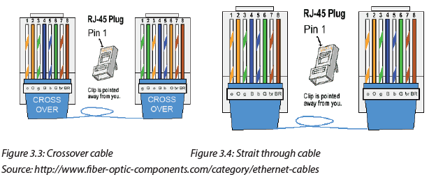
figure helps also to create the indicated cables.
a. Straight Cable
After making Ethernet cable we need to make them tested using cable tester using packet
tracer, we can connect devices using different cables not only packet tracer which can beused but also real computers depending on the resources/ computer lab.
Project II: Static IP address configuration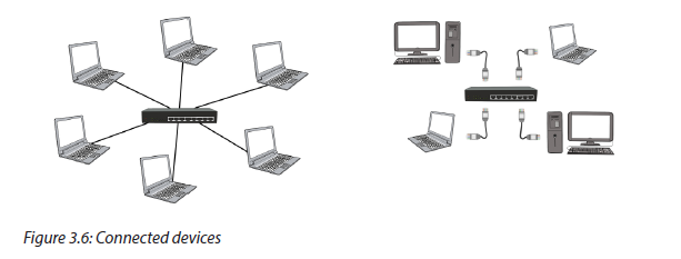
P2P Project 3.1. B
Using previous exercises P2P project 3.1.A, after arranging computers and connect
them with different cables accordingly do the following:
a. Define IP address scheme to be used
b. Assign each computer a static IP address
c. After assigning static IP address, test if they are connected using ping
command.
d. Identify the materials to be used for keeping devices clean.
Observation: By pinging each computer, the observation will be on the replies, if IP
address is assigned successfully, the packet sent will be equal to 4, received will be 4
and the lost will be 0, else it is not assigned successfully else repeat the process. If failedtwice call the teacher/Lab technician for guidance.
Step 4: Define IP address scheme
Listing IP addresses that will be used to different computers is an important step
that will be helpful to define the same working group for being able to share files,
folder, printers and network.
In this project we use maximum 10 computers which are allowed to build P2P
network, the IP addresses given to the PCs can be in the same network for being inthe same work group to share resources such as folder, printer, files and network.
The following are IP addresses we will use in this practice:
PC1: 192.168.0.1, PC2: 192.168.0.2, PC3: 192.168.0.3, PC4: 192.168.0.4,
PC5: 192.168.0.5, PC6: 192.168.0.6, PC7: 192.168.0.6, PC8: 192.168.0.8,
PC9: 192.168.0.9, PC10: 192.168.0.10
Step 5: Configure static IP address for each computer.
Process1: In windows 10, go to search and type in Control panel and click on it
Process2: Click the link “View network status and tasks” under the “Networkand Internet” heading.
Process 3: Click the link on the left of the window labeled Change adapter settings.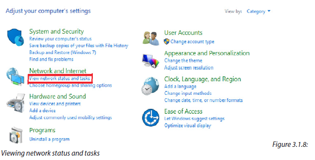
Process 3: change adaptor settings
Process 4: You might have more than one Internet connection listed in this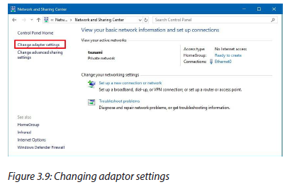
window. If this is the case you will need to determine which one is your connection
to the Internet. Once you have found it, right click on your network adapter andchoose properties to open up the properties window of this internet connection.
Process 5: Find the option of Internet Protocol Version 4 (TCP/IPv4) and click on
it. Then choose one option (Internet Protocol Version 4)
Process 6: Select “Use the following IP address” and enter the IP address,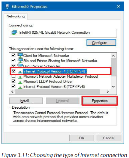
Subnet Mask, Default Gateway and DNS server. Click OK and close the Local AreaConnection properties window.
When choosing “Use the following IP address” the IP must be configured as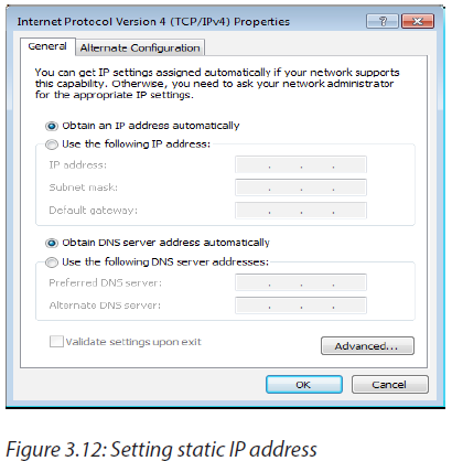
Static
Procces7: As an example, assign one PC1 an IP address of 192.168.0.1 and use the
subnet mask 255.255.255.0.For PC1
Procces 8: As an example, assign one PC2 an IP address of 192.168.0.2 and use the
subnet mask 255.255.255.0.
For PC2
Process 9: Do the same for other 8 PCs
Step 6: Ping each computer to verify if they are connected
Process 1: In windows 10, go to search and type in CMD then press Enter
Process 2: Type Ping 192.162.0.1 (if you use a computer assigned with
192.168.0.2 type in: ping 192.168.0.2) then press Enter button, the replies shouldbe as indicated in the figure below
Figure 3.1.15: IP address Replies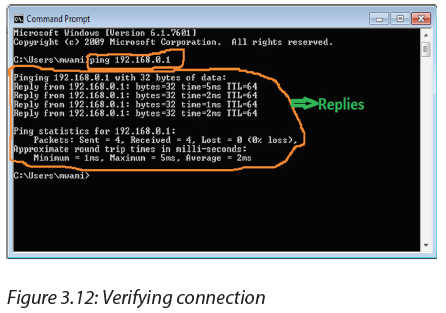
Step 7: Do the same as what you did on step 5 to all PCs
Note: if you receive timeout message when attempting to ping your selected IP
address, it is possible that the internet connection firewall is interfering, unpluggedcables, mistake on IP configuration, etc
How to allow internet connection through the firewall?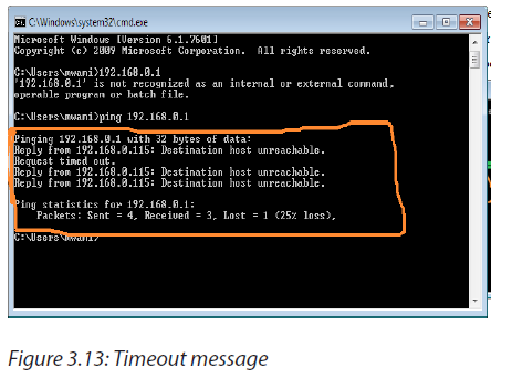
- Right click on My Network places, then select properties.
- Right click local Area connection and select properties once again,
- Click the advanced tab. Uncheck the box titled: protect my computer from
the internet.
- Click OK. Now, try typing the selected IP address again.
Once you get two computers to communicate successfully together, you can nowenjoy the benefit of files, printer, internet sharing.
Project III: Sharing folder, files, printer and internet
P2P Project 3.1.C
Using previous exercises P2P project 3.1.B, after assigning each computer its own IP address,
do the following
a. Put all computers in the same work group network
b. Share files, folder, printers and network.
c. How to avoid piracy in networking.
Observation: When files, folder, printer and internet are successfully to all permitted PCs,
they should be seen and retrieved on other PCs and enjoying using them when you are
in the same P2P network. The shared printer must print to every connected PC even if
there is no setup installed. If fails to share repeat the process once else call to the teacher/Lab technician for guidance
To share folder requires creating a home group/ workgroup, for the topic discussed
in S5, creating home group/ work group is discussed, here we need to change a
home group/ work group to be able to share files, folder, printer and network.
The following are the steps to change the home group/ workgroup in Windows 10
Step1: With the right mouse button click the Start icon and choose System. If you
have a touch enabled device, click and hold the start button, then tap the Systembutton.
Step2: Under “Computer name, domain, and workgroup settings” click on Change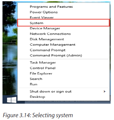
Settings
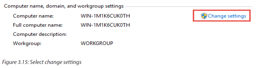
Step3: Under the tab “Computer Name” find the Change… button and click it
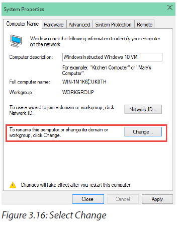
Step4: Under “Member Of” change the Workgroup name.
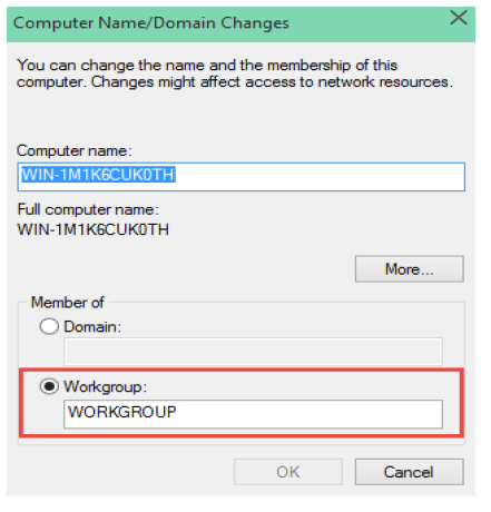
Figure 3.17: Select workgroup
Step 5: Change the name from WORKGROUP to S6A
Step 6: Then click on OK, the system will prompt to reboot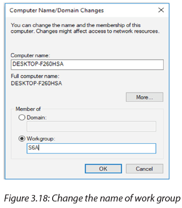
After rebooting the system, the new folder/files/printer or network will be added
to the existing Home group following the steps below
Step 1: Use the Windows key + E keyboard shortcut to open File Explorer
Step 2: On the left pane, expand your computer’s libraries on Home Group
Step 3: Right-click Documents and choose Properties
Step 4: Click Properties.Step 5: Click Add.
Step 6: Select the folder you want to share and click Include folder.
Step 7: Click Apply.
Step 8: Click OK.
Now the folder will be accessible by anyone who joined the Home Group when
they browse the Documents folder
3.2 Wireless Router installation and configuration
Note: This configuration is for TP-Link wireless Router, for other types of wireless
routers, consult manufacturer requirements and guidance.
Project I: Wireless router connection and Setting
P2P Project 3.1.C
Using previous exercises P2P project 3.1.B, after assigning each computer its own IP
address, do the following
a. Put all computers in the same work group network
b. Share files, folder, printers and network.
c. How to avoid piracy in networking.
Observation: When files, folder, printer and internet are successfully to all permitted PCs,
they should be seen and retrieved on other PCs and enjoying using them when you are
in the same P2P network. The shared printer must print to every connected PC even if
there is no setup installed. If fails to share repeat the process once else call to the teacher/
Lab technician for guidance
This unit provides procedures for configuring the basic parameters of your router;
it also describes the default configuration on startup.
3.2.1 Default configuration
When you first boot up the router, some basic configuration has already been
performed for TP-Link wireless router. All of the LAN and WAN interfaces have been
created, console and VTY (Virtual Teletype) ports are configured, and the inside
interface for Network Address Translation has been assigned.
3.2.2 Wireless Router configuration requirements
For some routers web browsers are needed to configure them to the wireless
router, others need Ethernet cables to be configured, they are also some which
needs their catalog where there is written all process to configure them.
To configure wireless Router the following materials are needed:
• A wireless router,
• A computer or laptop with wireless capabilities.
• Two Ethernet cables.
Step 1: Prepare router and switch on it.
Step2: Connect router to the Laptop/PC with wireless capability
Step3: Access Dashboard using default IP address and Password
The different process will be applicable when prompting to the Dashboard using
default IP and password.
Process1: Open the web browser and key in the address bar the default IP address
(192.168.0.1)
Process2: The server asks for the default username and password. The user willthen write in the form the default username and password
Process 3: Prompting default dashboard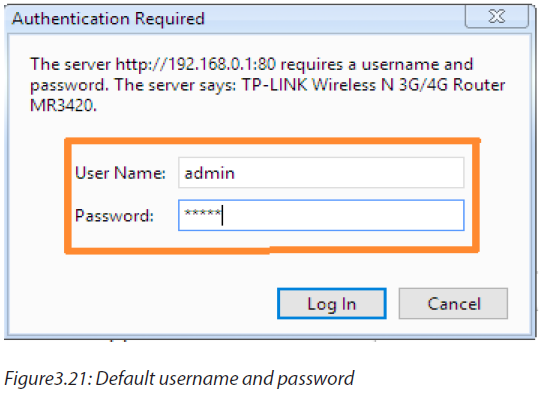
The figure below will be displayed after entering default username and password
Step4: Configure internet using information from the ISP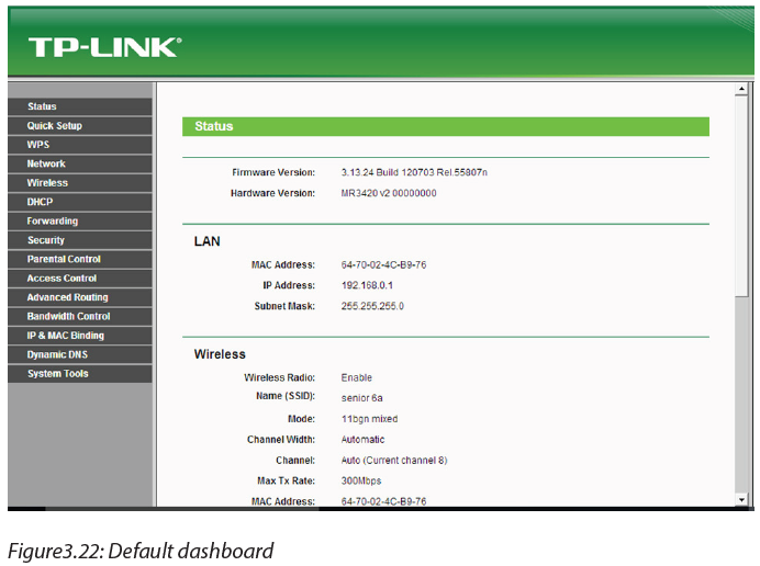
When configuring internet using information from ISP, some processes are
applicableProcess1: Click on Network then select internet mode and click Save
Process2: Click on Quick Setup to start configuring internet using information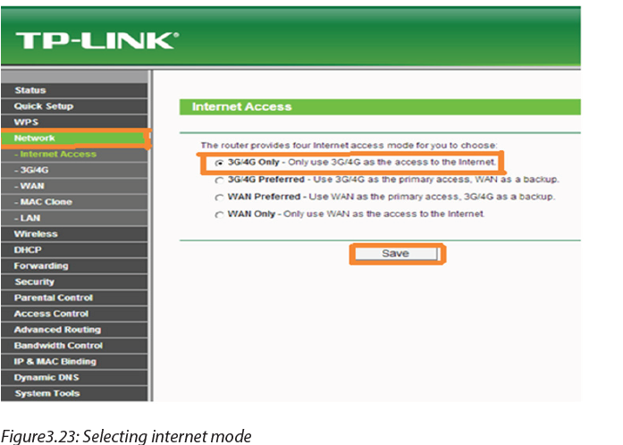
from ISP where the selected internet mode is activated, then click Next.
Process3: On Wireless name rename the existing name of wireless and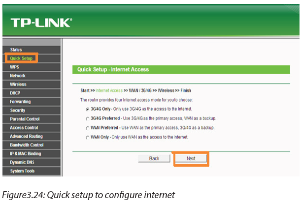
authenticate by set your own password for network protection.
In this practice, we use
Wireless name: senior 6aPassword: Kigali12
Process 3: After renaming Wireless and authentication, click Finish to apply the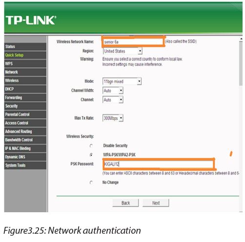
change, and then move to set DHCP settings.
Project II: Wireless security configuration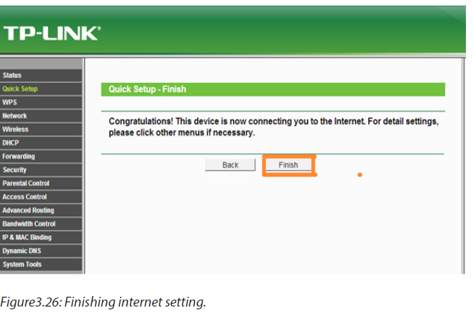
Wireless Router configuration Project 3.2.B
Following what is done in Wireless Router 3.2.A
a. Configure the wireless security
b. Set DHCP settings?
c. What measures would you take to keep data on router confidential?
Observation: If wireless router is successfully configured it will be seen on each device
which has capabilities to be connected to the wireless and using the name of the wireless
and password connect to verify if it is working, if it is not working repeat configurationonce if fails twice, call to the teacher for guidance.
Step5: configure LAN and IP using DHCP
Go to Wireless then Wireless Security and configure the wireless security. WPA/
WPA2-Personal is recommended as the most secure option. Once configured,
click Save.
There are many wireless security protocols. Here is a basic list ranking the current
Wi-Fi security methods available on any modern (post-2006) router, ordered from
best to worst: WPA2 + AES, WPA + AES, WPA + TKIP/AES (TKIP is there as a fallback
method), WPA + TKIP, WEP and Open Network (no security at all).
Ideally, you will disable Wi-Fi Protected Setup (WPS) and set your router to WPA2
+ AES. Everything else on the list is less than ideal step down from that. Once you
get to WEP, your security level is so low, it’s about as effective as a chain link fence.
The fence exists simply to say “hey, this is my property” but anyone who actuallywanted to go in could just climb right over it.
Note: If using a dual band router, repeat this process.
Step 5:
Go to DHCP→ DHCP Settings and select Disable the DHCP Server. Clickon Save.
Step 6: Set the IP from ISP and go to the System Tools and select Reboot to reboot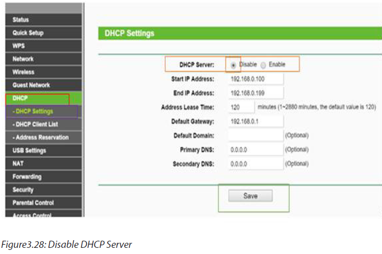
the device.
3.3 Building Client/Server network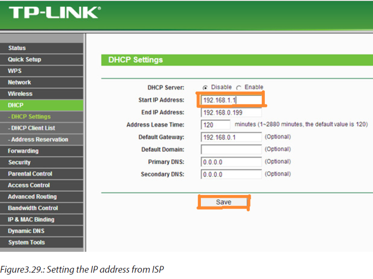
Project I: Creating and setting an FTP folder
Client/server project 3.3.A
1. You are given 2 computers and strait through cables
a. Create an FTP Folder
b. Configure IP address
c. Configure an FTP Server
d. When file is needed to be used by many people in the group, sometimes
printing or sending to flash disk is needed which is costly and sometimes
spread viruses. What measures would you take to avoid high cost and
virus spreading?
Observation: If the FTP folder is successfully created it will be available on server computer
and start enjoying using it for the next session to create an FTP site. If it fails once,call to the teacher/lab technician for guidance.
3.3.1 Creating an FTP client/server network
With a home FTP server, you are able to upload and download files from anywhere
to your PC, Similar to cloud storage but without the limitations.
Setting up a File transfer protocol (FTP) server may sound complicated, but it’s
actually quite easy to set up especially if using Windows 10.Step 1: Create a folder that your FTP users will be accessing on C: drive.
Step2: Press the “Windows key + R” on your keyboard to open the Run window,
and type CMD, click OK to open the command prompt window.
Step3: Here type “ipconfig” and press enter, write down the IP address and the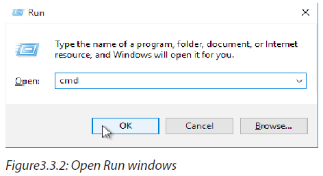
default gateway IP, because we are going to use it in the next steps. Here thefollowing IP addresses will be used: 10.0.0.17 and 10.0.0.1
Step4: Then go to Control Panel -> Programs and Features.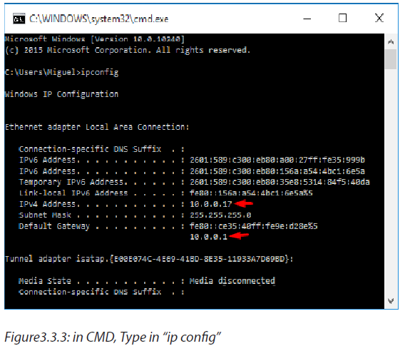
Step5: Navigate to Turn Windows features on or off on the top left.
Step 6: Select the check box, next to “Internet Information Services” also collapse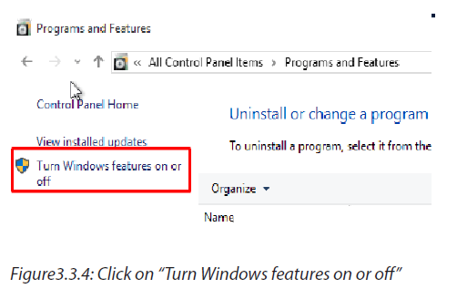
it to check mark “FTP Server” and “FTP Extensibility”, then click the OK button andwait for the features to be added.
Project II: Creating and setting an FTP site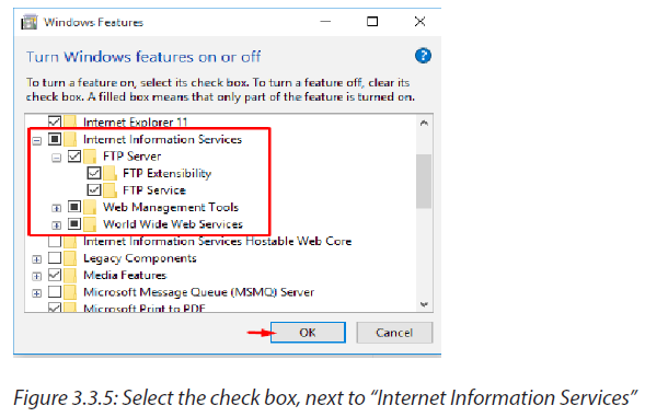
Client/server project 3.3.B
1. Following the steps client/project 3.3.A,
a. Create an FTP site
b. Create an Internet Information service site
c. How can you prevent unauthorized user to access your data?
Observation: If the FTP site is successfully created it will be available on server computer
and start enjoying by sharing folder, printers and files to the same client/server network.If it fails repeat the process or consult the teacher for guidance.
Step 7: Go to Control panel, Administrative tools,
Step 8: Choose Internet Information Services (IIS) Manager,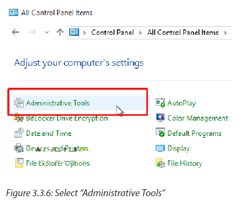
Step 9: Expand the root and right click on Sites to create a new FTP Site, click on“add FTP Site…”
Step10: Give your FTP site a name, such as “AvoidErrors”, and browse for the folder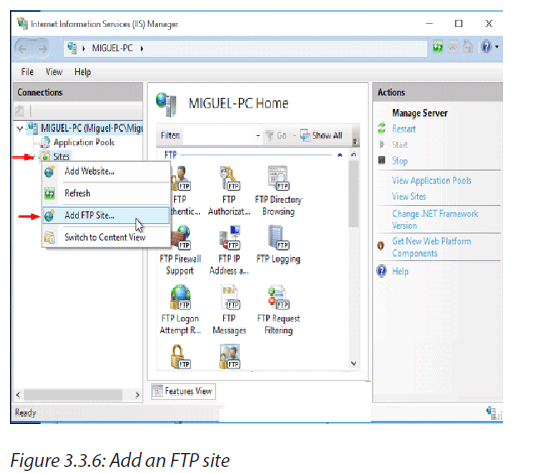
we created initially. This will be the default location where files will be accessible onthe server via FTP.
Step11: On the Binding and SSL Settings page, click on the drop down to select
the IP Address of the computer, Select “No SSL”. If you do have an SSL certificate,you can choose either “Require SSL” or “Allow SSL”.
Note: Be sure to require SSL if you intend to make this FTP server accessible via the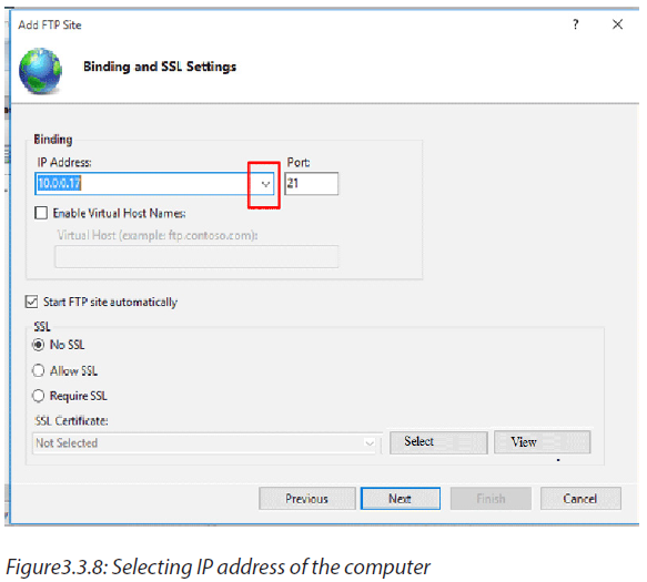
Internet.
On the Authentication and Authorization Information screen, change
“Authentication” option to “Basic” (requires that FTP users specify a login ID and
password).
Step13: Authorization section, select “Specified Users”, and Read & Write
permissions. Alternatively, you can choose specific user accounts or a group, and
limit permission to only Read or Write. Click Finish.Step13: Now your new IIS Site is properly created.
Step14: Create a local user account, and give to him/her permission on the FTP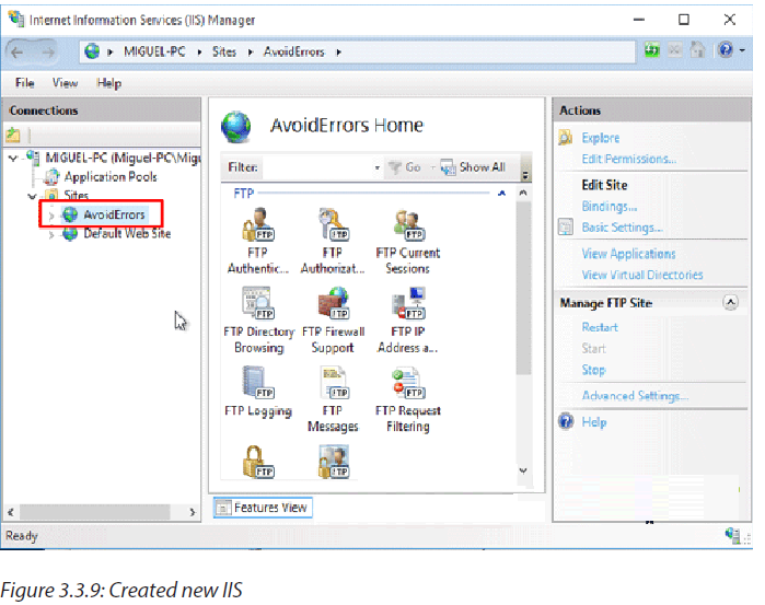
content directory:
*If you prefer to use an already existing local computer user account instead of
creating one you can skip the create user step and skip to open windows firewall
ports.
To allow additional users you must:
1. Create a Windows 10 user.
2. Create a new IIS Rule for the new user.
3. Add the new user to the security settings of the FTP folder.
Open firewall ports for FTP:Open Control Panel… (View by: “Small icons” recommended)… Windows
Firewall… Select “Allow an app or feature through windows firewall” -> Change
Settings button
Select the checkbox next to “FTP Server” and at least one of the networks, and thenclick on OK.
Project III: Creating rules and sharing folders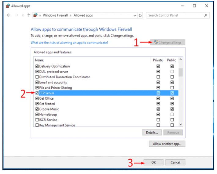
Client/server project 3.3.C
1. Following the project 3.3.B,
a. Enable FTP server port to be accessed from the LAN
b. Select proper management
c. Add the new user to the security settings of the FTP folder.
d. How can you avoid unauthorized users to access your folder
Observation: If the FTP client/server network is successfully configured the shared Folder,
printer, files and internet will be seen among all computers on the same network of
FTP server network, you can start enjoying using the shared files, folder and printers.Else repeat the process twice or call the teacher for guidance.
Now the Windows 10 FTP Server is enabled to be accessed from the LAN.
Step15: Once you have tested the FTP over the LAN than we are ready to access it
via WAN. To allow FTP connection you must enable Port 21 in your router’s firewallto allow incoming connection via FTP port 21.
Process1: Select the proper Site in IIS Manager and on the right, navigate to FTP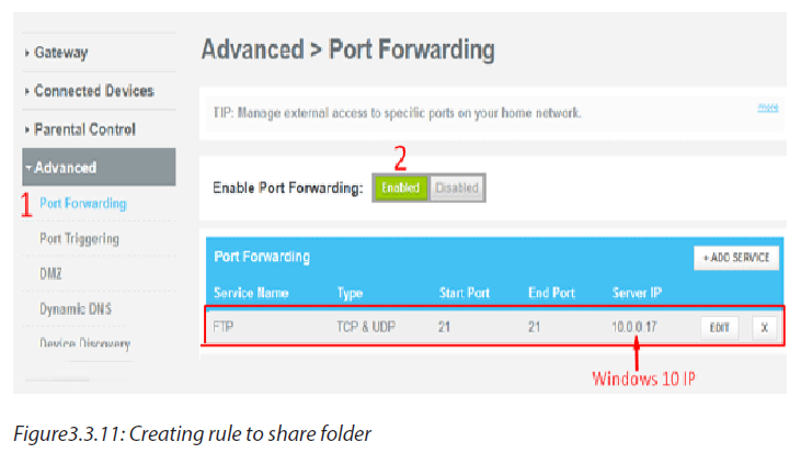
Authorization Rule.
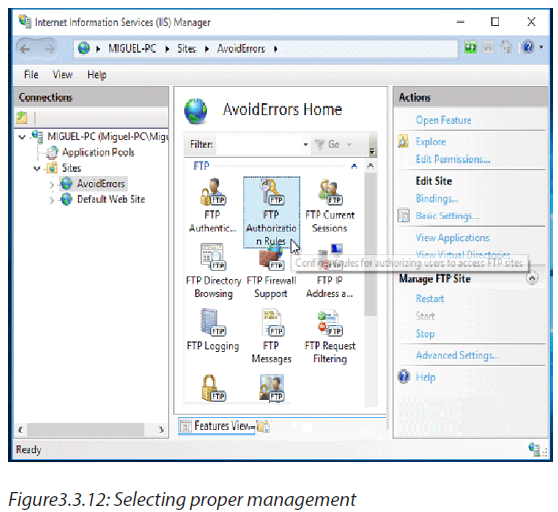
Process2: Right click an empty space and select Add Allow Rule…
Process3: Here check mark specified users and write the user name. Make sure is
first created in windows 10 and click OK.
To add the new user to the security settings of the FTP folder:
Process4: Locate the folder that your FTP users will be accessing (example: C:\FTPFolder),right click the folder… select Properties -> Security tab… and add the
user that was created in the previous step with appropriate permissions.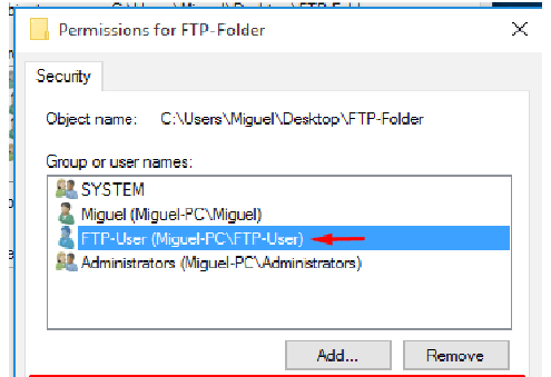
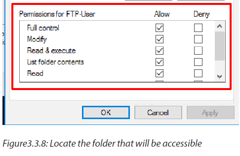
End unit activity
1. Lab activity: a given 5 computers with the following IP addresses:
198.162.0.117, 198.162.0.114, 198.162.0.118, 198.162.0.119,
198.162.0.116, the subnet mask is 255.255.255.0 assigned to all
computers
a. Create a P2P network
b. Add a home group and share folders, music and files to all computers.
2. You are given a server machine, three new laptop, three Ethernet
cables, and the following IP addresses: 198.162.0.12 and 198.162.0.13,create an FTP client/ server network and share folder.
UNIT 4 :SQL AND DATABASE PROJECT
UNIT 4: SQL AND DATABASE PROJECT
Key Unit Competency: To be able to apply Structured Query Language in RDBMS
and create a short database project
Introductory activity:
The school is requested to submit a report to the District indicating the data on
students, teachers, rooms and courses.
In groups, conduct a survey in your school and answer the following questions:
i. How many students are in the schools?
ii. How many student are in each class?
iii. How many boys are in the school? How many boys are in each class?
iv. How many are girls in the school? How girls are many in each class?
v. What is the number of teachers in the schools?
vi. How many teachers for Mathematics Subjects
vii. How many rooms are there in the school?
viii. How can you choose the courses that can be taught in the same
room?
ix. Show the number of students eligible to get National Identity card.
x. How do you think the school does such reporting according to these
criteria?
a. Design the entities student, teacher, room and course
b. Using the used RDBMS (MS Office Access) in the school computer
lab, create the database of the school with the 3 tables representing
the entities above.
c. Respond again to the sub questions in question a) by querying your
database. Are the answers the same? What is used to get the answerto each answer?
Activity 4.1:
4. Kabeza Company Ltd is running a business and wishes to manage
transactions in computerized way. The database of business contains
various entities including “Customers” (id, name, age, address, salary)
and orders (id,date,customer_id, amount) which are given here below.
Help your school to find a solution to get the following:
i. The highly paid employee
ii. The least paid employee
iii. The oldest employee
iv. The youngest employee
v. To generate total amount of income at a given day.
vi. To retrieve only the names and age of all employees
vii. To retrieve the average income at a given day.
“Customers” table:i. σage>=23 AND address≠ kigali(“Customers”)
Definition: relational algebra is the one whose operands are relations or variables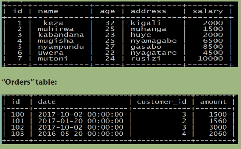
that represent relations.
4.1.1 Unary operations
By definition a unary operation is an operator that uses only one operand (relation).
In Relational algebra, the unary operations are selectionand projection
4.1.1.a Selection operation
Selection is a unary operation that selects records satisfying a given predicate
(criteria). It selects a subset of records. The lowercase Greek letter sigma (σ) is used to
denote selection. The selection condition appears as a subscript to σ. The argumentrelation is given in parenthesis following the σ.
Select Operation Notation Model
Syntax: σ selection_condition (Relation)
The selection condition or selection criterion can be any legally formed expression
that involves:
1. Constants (i.e, members of any attribute domain)
2. Attributes names
3. Arithmetic operators(+,*,/,-,%)
4. Comparisons/Relational operators : a. in mathematicl algebra(=,≠,<,>,≤,≥)
b.in relational algebra (=,<,<=,>,>=)
5. Logical operators( And,Or, Not)
Example of using selection operation within a relation: σ last_name=’Mugisha’
(“Customers”) where the table “Customers” in learning activities 4.1 is considered.The result is a binary relation listing all the “Customers” with the name Mugisha.
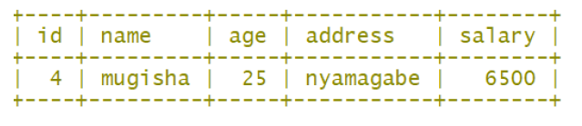
result of σ name=’Mugisha’ (“Customers”)
Application activity 4.1:
Using the table “Customers” in learning activities 4.1, what is the result of the
following statements?
i. σ Salary>2000 (“Customers”)ii. σage>=23 AND address≠ kigali(“Customers”)
4.1.1.b Projection operation
Activity 4.2
From the table “Customers”, display the following table with only twocolumns name and age
Result for π name,age (“Customers”)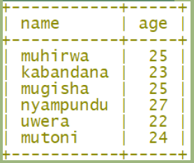
The PROJECT operation is another unary operation. This operation returns a set of
tuples containing a subset of the attributes in the original relation. Thus, we state
that the SELECT operation selects some rows and discards the others. The PROJECT
operation, on the other hand, selects some columns of the relation and discards
the other column. The PROJECT operation can be viewed as the vertical filter of the
relation.
The projection operation copies its arguments relation, but certain columns are left
out. The projection operation lists the desired attributes to appear in the result as a
subscript to π.
Projection is unary operation denoted by the Greek letter pi (π).
• Syntax: πattribute−list(r)
• Eg: Π attribute_1, attribute_2,…, attribute_n(Relation)Project Operation Notation Model:
Notice that if the projection produces two identical rows, the duplicate rows must be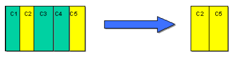
removed since the relation is a set and it is not allowed to contain identical records.Eg:Example: Retrieve the suburbs that are stored in database
Application activity 4.2: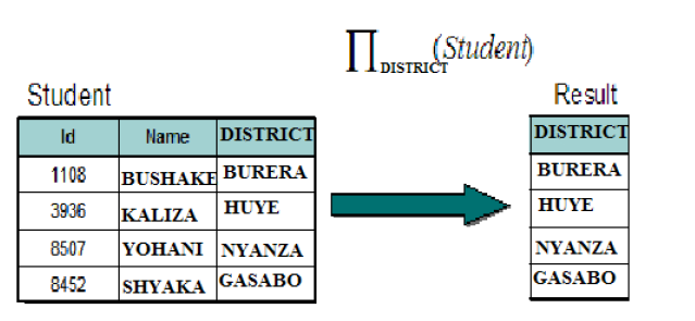
What is the result of the following statements?
i. π ID, Address (“Customers”)ii. π name,Salary(σSalary>5000) (“Customers”)
4.1.2 Binary operations
A binary operation is an operation that uses two operands (relations). In Relational
algebra, the binary operations are Cartesian product, Union operator, Set Difference,Intersection, Theta-join and Natural Join.
Activity 4.3:We have two relations, student and subject, as follows:
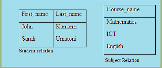
How can be generated the following table?
The Cartesian product of two relations, R1 and R2, is written in infix notation as
R1xR2. To define the final relation scheme, we need to use fully qualified attribute
names. Practically, it means we attach the name of the original relation in front of
the attribute. This way we can distinguish R1.A from R2.A. If R1(A1,A2,…,An) and
R2(A1,A2,…,An) are relations, then the Cartesian product R1xR2 is a relation with
a scheme containing all fully qualified attribute names from R1 and R2R1.A1,…
R1.An,R2.A1,….R2.An).
The records of Cartesian product are formed by combining each possible pair
of records: one from the R1 relation and another from the R2 relation. If there are
n1 records in R1 and n2 records in R2, then there are n1*n2 records in their Cartesianproduct.
The results of a Cartesian product is a relation whose scheme is a concatenation
of student scheme and subject scheme. In this case, there are no identical attribute
names. For that reason, we do not need to use the fully qualified attribute names.
Student relation contained 2 records, subject relation 3, therefore, the result has 6
records (2 times 3).
Note that the Cartesian product contains no more information than its components
contain together. However, the Cartesian product consumes much more memory
than the two original relations consume together. These are two good reasons why
Cartesian product should be de-emphasized, and used primarily for explanatory orconceptual purpose.
Application activity 4.3:
Carry out the following activity:
A. Union operator
Activity 4.4:
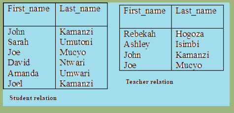
What was the operation performed in order to get this table?
The result of the query are all the people (students and teachers) appearing in either
or both of the two relations. Again, since relations are sets, duplicate values are
dropped.
The binary operation Union is denoted, as in set theory, by U. Union is intended
to bring together all of the facts from its arguments, however, the relational union
operator is intentionally not as general as the union operator in mathematics.
We cannot allow for an example that shows union of a binary and a ternary relation,
because the result of such union is not a relation. Formally, we must ensure that
union is applied to two union compatible relations. Therefore, for a union operatorR1UR2 to be legal,it is required that two conditions be held:
1. The relations R1 and R2 are of the same arity. Which means, they have the
same numbers of attributes.2. The domains of the ith attribute of R1 and ith attribute of R2 are the same.
Application activity 4.4:Carry out the following activity:
B. Set Difference
Activity 4.5:From the following table:
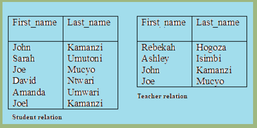
What is the operation performed in order to generate the following table?
The last fundamental operation we need to introduce is set difference. The set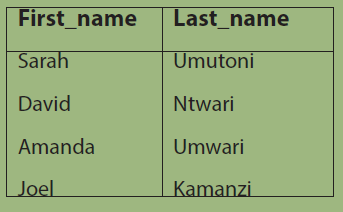
difference, denoted by - is a binary operator. To apply this operator to two relations,
it is required for them to be union compatible. The result of the expression R1-R2,
is a relation obtained by including all records from R1 that do not appear in R2. Of
course, the resulting relation contains no duplicate records.
Note that if the relations are union compatible, applying “set difference” to them is
allowed.
C. Intersection
The first operation we add to relational algebra is intersection, which is a binary
operation denoted by ∩ symbol. Intersection is not considered a fundamental
operation because it can be easily expressed using a pair of set difference operations.
Therefore, we require the input relations to union compatible.
After applying the intersection operator, we obtain a relation containing only those
records from r1 which also appear as records in r2.We do not need to eliminate
duplicate rows because the resulting relation cannot contain any (since neither of
the operands contain any).
Practical example:Consider relations R and S
D. Join operations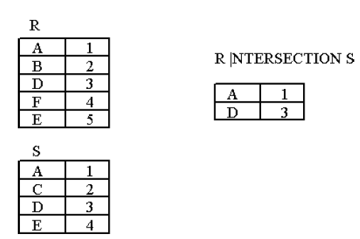
SQL Joins can be classified into Equi join and Non Equi join.
1. SQL Equi joins
It is a simple sql join condition which uses the equal sign as the comparison operator.
Two types of equi joins are SQL Outer join and SQL Inner join.
For example: You can get the information about a customer who purchased a
product and the quantity of product.
2. SQL Non equi joins
Types of Joins:
Join is a special form of cross product of two tables. It is a binary operation that
allows combining certain selections and a Cartesian product into one operation.
The The join operation forms a Cartesian product of its two arguments, performs a
selection forcing equality on those attributes that appear in both relation schemas,
and finally removes duplicate attributes. Following are the different types of joins:
Theta Join, Equi Join, Semi Join, Natural Join and Outer Joins
We will now discuss them one by one
1. Theta Join:
In theta join we apply the condition on input relation(s) and then only those selected
rows are used in the cross product to be merged and included in the output. It means
that in normal cross product all the rows of one relation are mapped/merged with
all the rows of second relation, but here only selected rows of a relation are made
cross product with second relation. It is denoted as RX S
For example there are two relations of FACULTY and COURSE now first apply select
operation on the FACULTY relation for selection certain specific rows then these
rows will have a cross product with COURSE relation, so this is the difference in
between cross product and theta join. From this example the difference betweencross product and theta join becomes clear.
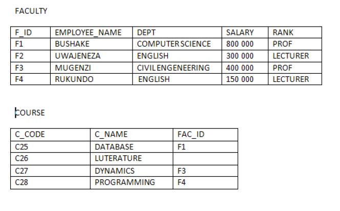
2. Equi¬ Join: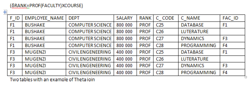
This is the most used type of join. In equi¬join rows are joined on the basis of values
of a common attribute between the two relations. It means relations are joined on
the basis of common attributes between them; which are meaningful. This means on
the basis of primary key, which is a foreign key in another relation. Rows having the
same value in the common attributes are joined. Common attributes appear twice in
the output. It means that the attributes, which are common in both relations, appear
twice, but only those rows, which are selected. Common attribute with the same
name is qualified with the relation name in the output. It means that if primary and
foreign keys of two relations are having the same names and if we take the equi ¬
join of both then in the output relation the relation name will precede the attribute
name. For Example, if we take the equi ¬ join of FACULTY and COURSE relations thenthe output would be
3. Natural Join: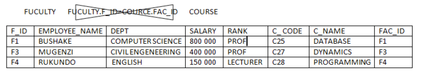
This is the most common and general form of join. If we simply say join, it means
the natural join. It is same as equi¬ join but the difference is that in natural join,
the common attribute appears only once. Now, it does not matter which common
attribute should be part part of the output relation as the values in both are same.To join the tables use this symbol:

4. Outer Join:
This join condition returns all rows from both tables which satisfy the join condition
along with rows which do not satisfy the join condition from one of the tables.
The Outer Join has three forms:
a. Left Outer Join:
In a left outer join all the tuples of left relation remain part of the output. The tuples
that have a matching tuple in the second relation do have the corresponding tuple
from the second relation. However, for the tuples of the left relation, which do not
have a matching record in the right tuple, have null values against the attributes of
the right relation. Left outer join is the equi-join plus the non matching rows of theleft side relation having null against the attributes of right side relation.
The following example shows how Left Outer Join operation works:Consider the relation BOOK and relation STUDENT
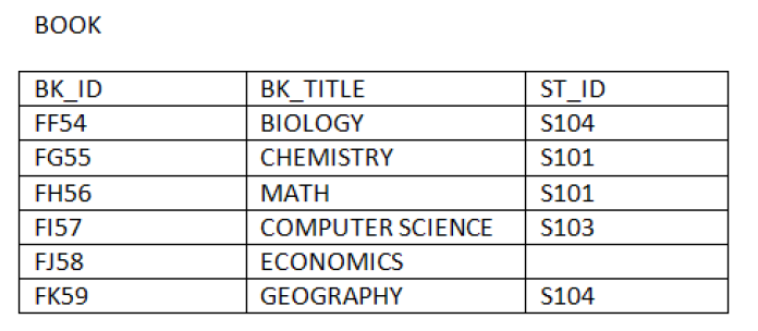
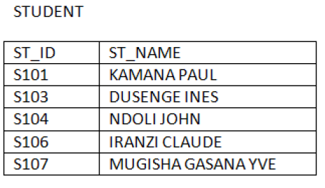
b. Right Outer Join: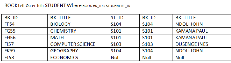
In right outer join all the tuples of right relation remain part of the output relation,
whereas on the left side the tuples, which do not match with the right relation,
are left as null. It means that right outer join will always have all the tuples of right
relation and those tuples of left relation which are not matched are left as Null. The
following example shows how Right Outer Join operation works:Consider the Relation BOOK and Relation STUDENT
c. Full Outer Join:
In outer join all the tuples of left and right relations are part of the output. It means
that all those tuples of left relation which are not matched with right relation are
left as null. Similarly all those tuples of right relation which are not matched with left
relation are left as null.
The following example shows how Right Outer Join operation works:Consider the relation BOOK and relation STUDENT
d. Division Operator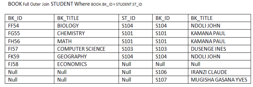
Division identifies attribute values from a relation that are paired with all of thevalues from another relation.
Application activity 4.5:
1. Solve the following relational expressions for these relations:User
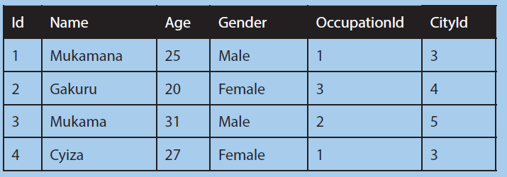
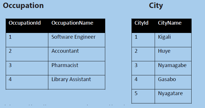
a. πName(δ(Age>25)(User)) same as δName(δAge>25)(User)
b. δ(Id>2∨Age!=31)(User)
c. δ(User.OccupationId=Occupation.OccupationId)(User X Occupation)
d. πName,Gender(δCityId=1User ⋈ City))
2. With clear example, differentiate unary operators and binary operators.
3. Use an example and explain projection and selection operations.4. Consider ABC database containing the following relations:
Representative (number, surname, firstname, committee, county)
Counties (code, name, region)
Regions(code, name)
Committees (number, name, president)
Formulate the following queries in relational algebra, in domain calculus and
in record calculus:
• Find the number and surname of the Representatives from the country
of Rwanda;
• Find the name and surname of representatives;
• Find the members of the finance committee;
• Find the name, surname, country and region of election of the
delegates of the finance committee;
• Find the regions in which representatives having the same surname
have been elected.
5. Consider the DEFG database schema with the relations:
Courses (number, faculty, coursetitle, tutornumber)
Students (number, surname, firstname, faculty)
Tutors (number. surname, firstname)
Exams (studentnumber, coursenumber, grade, date)
Studyplan( studentnumber, coursenumber, year)
* Formulate in relational algebra the queries that produce:
* The students who have gained an ‘A’ in at least one exam, showing, for
each of them, the first name, surname and the date of the first of such
occasions;
* For every course in the engineering faculty, the students who passed
the exam during the last session;
* The students who passed all the exams required by their respective
study plans;
* For every course in the literature faculty, students who passed the
exam with the highest grades;
* The students whose study plans require them to attend lectures only
in their own faculties;
* First name and surname of the students who have taken an exam witha tutor having the same surname as the student.
4.2 Structured Query language
Activity 4.6:
1. Consider the following relational schema of HIJK database;
Departments (Dept_Code (integer), name (text) , Budget (number)) Employees (SSN
(integer), first_name (text), last_name (text), Dept_Code (integer, foreign key) Write SQL
query to:
i. Create the above relations (tables)
ii. Add at least ten records
iii. Select the last name of all employees, without duplicates.
iv. Select all the data of employees whose first name is "Peter" or "Diane".
v. Retrieve the sum of all the departments’ budgets.
vi. Retrieve all the data of employees whose last name begins with letter
"U".
vii. Show the number of employees in each department (you only need to
show the department code and the number of employees).
viii. Select the name and last name of employees working for departments
with a budget greater than 6,000,000 (currency: Rwf)
ix. Show the departments with a budget larger than the average budget of
all the departments.
x. Add a new department called "Quality Assurance", with a budget of
4,000,000 (currency: Rwf) and departmental code 11. Add an employee
called "KAMANA" in that department, with SSN 847-21-9811.
xi. Reduce the budget of all departments by 10%.xii. Delete from the table all employees in the IT department (code 14).
4.2.0. Introduction
SQL which is an abbreviation for Structured Query Language, is a language to
request data from a database, to add, update, or remove data within a database, or
to manipulate the metadata of the database.
Commonly used statements are grouped into the following categories:
DML: Data Manipulation LanguageDDL: Data Definition Language
DCL: Data Control Language
4.2.1 Data Definition Language (DDL)
a. To create a new database, the SQL query used is CREATE DATABASE
The Syntax is:
create database databasename;
Always database name should be unique within the RDBMS. Example of a query to
create a database called XYZLtdCREATE DATABASE XYZLtd; In MYSQL, it will look like the following:
Make sure that the user has admin privilege before creating any database.
b. To display the list of all databases created, the SQL query is SHOW
databases;
Once a database is created, the user can check it in the list of databases as follows:
Show databases;If the RDBMS used is MYSQL, the result will look like this:
c. Before using a database, the SQL command USE helps to select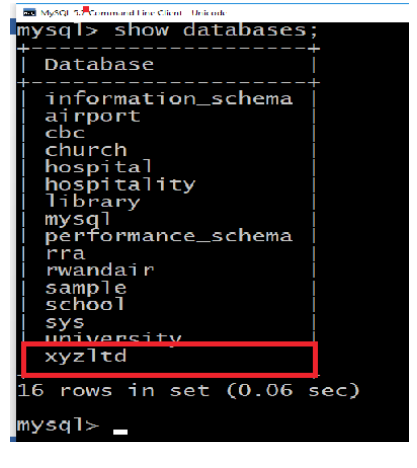
the name of the database.
The SQL USE statement is used to select any existing database in the SQL schema.
Syntax: The basic syntax of the USE statement is as shown below: Always the
database name should be unique within the RDBMS. Now, if the user wants to work
with the XYZLtd database, then he/shecan execute the following SQL commandand start working with the School database.
d. After creating a database and entering in it, there is a need now
to create table
Creating a basic table involves naming the table and defining its columns and each
column’s data type. The SQL CREATE TABLE statement is used to create a new table.
the basic syntax of CREATE TABLE statement is as follows:
create table table_name (column1 datatype, column2 datatype, column3 datatype,
..... columnn datatype,
primary key( one or more columns ) );
CREATE TABLE is the keyword telling the database system what you want to do. In
this case, you want to create a new table. The unique name or identifier for the table
follows the CREATE TABLE statement.
Then in brackets comes the list defining each column in the table and what sort of
data type it is. The syntax becomes clearer with an example below.
Activity 4.7:
The following SQL query creates a “Customers” table with ID as primary key and NOT
NULL and thereafter, when the table was successfully created, the message “Query OK,o rows affected (0.48 sec)” is displayed. See below.
The user can verify if the table has been created successfully by looking at the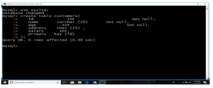
message displayed by the SQL server, otherwise he/she can use DESC command asfollows:
Now, “Customers” table is created and available in database. It can be used to store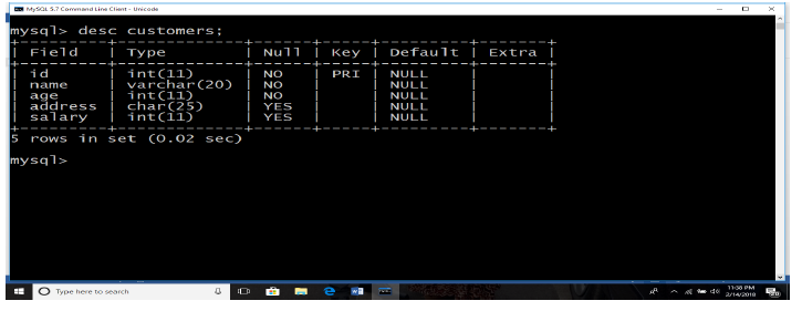
required information related to “Customers”.
Notice that DESC is the same as DESCRIBE is some RDBMS.
e. Create Table Using another Table:
A copy of an existing table can be created using a combination of the CREATE TABLE
statement and the SELECT statement.
The new table has the same column definitions. All columns or specific columns can
be selected.
When you create a new table using existing table, new table would be populated
using existing values in the old table.
The basic syntax for creating a table from another table is as follows:create table new_table_name as like existing_table_name [ where ]
Example:
To create a table called SALARY having the same attributes like table “Customers”,
writeCreate table salary like “Customers”;

The structure of SALARY is displayed in the following interface.
f. To remove a table from a database, use the SQL Command “DROP TABLE”.
The SQL DROP TABLE statement is used to remove a table definition and all its data.
Notice that the user has to be careful while using this command because once
a table is deleted then all the information available in the table would also be lost
forever.The Basic syntax of DROP TABLE statement is as follows:
Example:
DROP TABLE “Customers”;
To make sure that the table has been removed, check withDESC “Customers”; and the answer will be like the following:
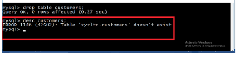
“CUSTOMERS” Relation
g. To add, delete or modify columns in an existing table, use the SQL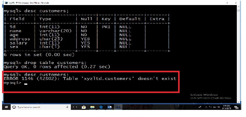
Command ALTER TABLE followed by either ADD or DROP or MODIFY.
ALTER TABLE command can also be used to add and drop various constraints on anexisting table.
The basic syntax of ALTER TABLE to add a new column in an existing table is as
follows:alter table table_name add column_name datatype;
The basic syntax of ALTER TABLE to DROP COLUMN in an existing table is as follows:alter table table_name drop column column_name;
The basic syntax of ALTER TABLE to change the DATA TYPE of a column in a table is
as follows:alter table table_name modify column column_name datatype;
The basic syntax of ALTER TABLE to add a NOT NULL constraint to a column in a
table is as follows:alter table table_name modify column_name datatype not null;
The basic syntax of ALTER TABLE to ADD UNIQUE CONSTRAINT to a table is as
follows:
alter table table_nameadd constraint myuniqueconstraint unique(column1, column2...);
The basic syntax of ALTER TABLE to ADD CHECK CONSTRAINT to a table is as follows:
alter table table_nameadd constraint myuniqueconstraint check (condition);
The basic syntax of ALTER TABLE to ADD PRIMARY KEY constraint to a table is as
follows:
alter table table_name add constraint myprimarykey primary key (column1,column2...);
The basic syntax of ALTER TABLE to DROP CONSTRAINT from a table is as follows:alter table table_name drop constraint myuniqueconstraint;
If you’re using MySQL, the code is as follows:alter table table_name drop index myuniqueconstraint;
The basic syntax of ALTER TABLE to DROP PRIMARY KEY constraint from a table is
as follows:alter table table_name drop constraint myprimarykey;
If you’re using MySQL, the code is as follows:alter table table_name drop primary key;
Application activity 4.7:
You are given a flat database named “Library”, with a relation Book (ISBN (Text,
primary key), title (text), author (text), pages (integer), and price (integer)) Create
this database and relation, then insert at least five records.
4.2.1.a SQL Constraints
Activity 4.8:
Consider “Customers” relation, perform the following tasks;
i. Add new column “sex”
ii. Change the datatype of salary to decimals
iii. Add “Not null” constraint to age field (column)
iv. Remove the column “sex”
v. Drop “not null” constraint from age field.
Constraints are the rules enforced on data columns of a table. These are used to limit
the type of data that can go into a table. This ensures the accuracy and reliability of
the data in the database.
Constraints could be column level or table level. Column level constraints are applied
only to one column whereas table level constraints are applied to the whole table.
Following are commonly used constraints available in SQL. These constraints have
already been discussed inSQL - RDBMS
Following are commonly used constraints available in SQL:
• Not null constraint: ensures that a column cannot have null value.
• Default constraint: provides a default value for a column when none is
specified.
• Unique constraint: ensures that all values in a column are different.
• Primary key: uniquely identified each rows/records in a database table.
• Foreign key: uniquely identified a row/record in any other database table.
• Check constraint: the check constraint ensures that all values in a column
satisfy certain conditions.
• Index: use to create and retrieve data from the database very quickly.• NOT NULL Constraint:
By default, a column can hold NULL values. If the user does not want a column to
have a NULL value, then he/she needs to define such constraint on this column
specifying that NULL is now not allowed for that column. A NULL is not the same as
no data, rather, it represents unknown data.
Example:
For example, the following SQL query creates a new table called “CUSTOMERS” and
adds five columns, three of which, ID and NAME and AGE, specify not to acceptNULLs:
create table “Customers”(
id int not null,
name varchar (20) not null,
age int not null,
address char (25) ,
salary Int,
primary key (id));
a. DEFAULT Constraint:
The DEFAULT constraint provides a default value to a column when the INSERT INTO
statement does not provide a specific value.
Example:
For example, the following SQL creates a new table called “CUSTOMERS” and adds
five columns. Here, SALARY column is set to 5000 by default, so in case INSERT INTO
statement does not provide a value for this column, then by default this columnwould be set to 5000.
If “Customers” table has already been created, then to add a DEFAULT constraint to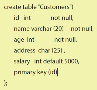
SALARY column, write a statement similar to the following:
Drop “Default” Constraint:
To drop a DEFAULT constraint, use the following SQL:
b. UNIQUE Constraint:
The UNIQUE Constraint prevents two records from having identical values in a
particular column. In the “Customers” table, for example, you might want to prevent
two or more people from having identical age.
Example:
For example, the following SQL creates a new table called “CUSTOMERS” and adds
five columns. Here, AGE column is set to UNIQUE, so that you cannot have tworecords with same age:
If “CUSTOMERS” table has already been created, then to add a UNIQUE constraint to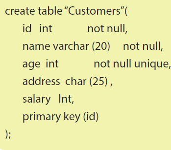
AGE column, you would write a statement similar to the following
The user can also use the following syntax, which supports naming the constraint in
multiple columns as well:
Drop a UNIQUE Constraint:
To drop a UNIQUE constraint, use the following SQL:

If you are using MySQL, then you can use the following syntax
c. PRIMARY Key:
A primary key is a field in a table which uniquely identifies each row/record in a
database table. Primary keys must contain unique values. A primary key column
cannot have NULL values.
A table can have only one primary key, which may consist of single or multiple fields.
When multiple fields are used as a primary key, they are called a composite key.
If a table has a primary key defined on any field(s), then it is impossible to have two
records having the same value of that field(s).
Notice that these concepts can be used while creating database tables.The syntax to define ID attribute as a primary key in a “CUSTOMERS” table is:
To create a PRIMARY KEY constraint on the “ID” column when “CUSTOMERS” table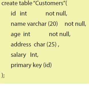
already exists, use the following SQL syntax:
Alter table customers add primary key (ID);
Notice that to use the ALTER TABLE statement to add a primary key, the primary key
column(s) must already have been declared to not contain NULL values (when the
table was first created).
For defining a PRIMARY KEY constraint on multiple columns, use the following SQLsyntax:
To create a PRIMARY KEY constraint on the “ID” and “NAMES” columns when
“CUSTOMERS” table already exists, use the following SQL syntax:
To delete the Primary Key constraints from the table,
, use the Syntax:
d. FOREIGN Key:
A foreign key is a key used to link two tables together. This is sometimes called a
referencing key.
The Foreign Key is a column or a combination of columns, whose values match aPrimary Key in a different table.
The relationship between 2 tables matches the Primary Key in one of the tables with
a Foreign Key in the second table.
If a table has a primary key defined on any field(s), then you cannot have two records
having the same value of that field(s).
Example:
Consider the structure of the two tables as follows:“CUSTOMERS” table:

ORDERS table:
If ORDERS table has already been created, and the foreign key has not yet been, use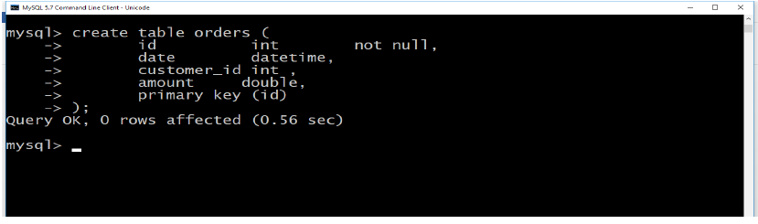
the syntax for specifying a foreign key by altering a table.
Drop a FOREIGN KEY Constraint:
To drop a FOREIGN KEY constraint, use the following SQL:
e. CHECK Constraint:
The CHECK Constraint enables a condition to check the value being entered into a
record. If the condition evaluates to true, the record violates the constraint and isn’t
entered into the table.
Example:
For example, the following SQL creates a new table called “CUSTOMERS” and adds
five columns. Here, we add a CHECK with AGE column, so that you cannot have anyCustomer below 18 years:
If “Customers” table has already been created, then to add a CHECK constraint to AGE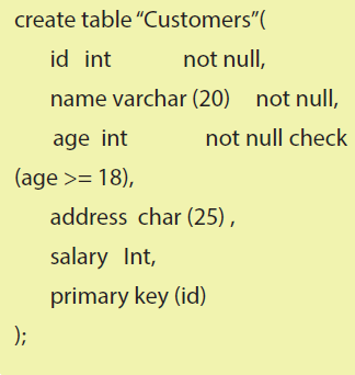
column, you would write a statement similar to the following:
You can also use following syntax, which supports naming the constraint and
multiple columns as well:
Drop a CHECK Constraint:
To drop a CHECK constraint, use the following SQL. This syntax does not work withMySQL:
Dropping Constraints:
Any constraint that you have defined can be dropped using the ALTER TABLE
command with the DROP CONSTRAINT option.
For example, to drop the primary key constraint in the EMPLOYEES table, you canuse the following command:
Some implementations may provide shortcuts for dropping certain constraints. For
example, to drop the primary key constraint for a table in Oracle, you can use thefollowing command:
Some implementations allow you to disable constraints. Instead of permanently
dropping a constraint from the database, you may want to temporarily disable theconstraint, and then enable it later.
Integrity Constraints:
Integrity constraints are used to ensure accuracy and consistency of data in a
relational database. Data integrity is handled in a relational database through the
concept of referential integrity.
There are many types of integrity constraints that play a role in referential integrity
(RI). These constraints include Primary Key, Foreign Key, Unique Constraints and
other constraints mentioned above.
4.2.2 Data Manipulation Language (DML)
A. Insert into command
The SQL INSERT INTO Statement is used to add new rows of data into a table in the
database.
There are two basic syntaxes of INSERT INTO statement as follows:
insert into table_name (column1, column2, column3,...columnn)] values
(value1, value2, value3,...valuen);
Here, column1, column2,..columnN are the names of the columns in the table into
which you want to insert data.
You may not need to specify the column(s) name in the SQL query if you are adding
values for all the columns of the table. But make sure the order of the values is in the
same order as the columns in the table. The SQL INSERT INTO syntax would be asfollows:
Activity 4.9:
Create/ insert six records in “Customers” table (relation). Use two possibleways to insert records (tuples) in a table:
First method:
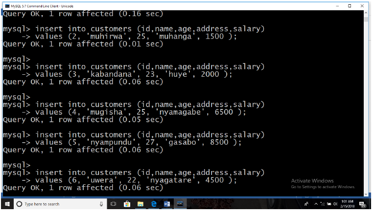
Second method:
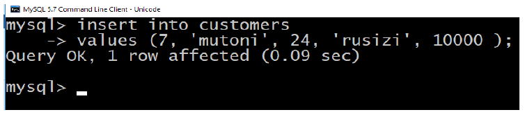
All the above statements would produce the following records in “Customers” table:
B. Select statement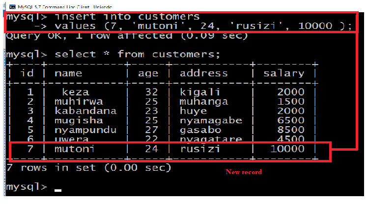
The SELECT statement is used to select data from a database. The data returned is
stored in a result table, called the result-set.SELECT Syntax
Here, column1, column2,... are the field names of the table you want to select data
from. If you want to select all the fields available in the table, use the following syntax:
SELECT * (Select all)
The following SQL statement selects all the columns from the ““Customers”” table:SELECT * FROM “Customers”;
The SQL SELECT DISTINCT Statement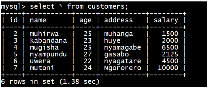
The SELECT DISTINCT statement is used to return only distinct (different) values.
Inside a table, a column often contains many duplicate values; and sometimes you
only want to list the different (distinct) values. The SELECT DISTINCT statement isused to return only distinct (different) values.
SELECT DISTINCT Syntax
SELECT Example
The following SQL statement selects all (and duplicate) values from the “Address”
column in the ““Customers”” table:
Example
SELECT Address FROM “Customers”;
WHERE Clause Example
The following SQL statement selects all the “Customers” from the address “Muhanga”,
in the “Customers” table:
Example
SELECT * FROM “Customers”
WHERE Address=’Muhanga’;
The SQL AND, OR and NOT Operators
The WHERE clause can be combined with AND, OR, and NOT operators. The AND,
OR operators are used to filter records based on more than one condition: The AND
operator displays a record if all the conditions separated by AND are TRUE. The OR
operator displays a record if any of the conditions separated by OR is TRUE. The NOToperator displays a record if the condition(s) is NOT TRUE.
AND Example
The following SQL statement selects all fields from ““Customers”” where address is
“Nyamagabe” AND address is “Huye”:
Example
SELECT * FROM “Customers” WHERE Address=’Nyamagabe’ AND Address=’Huye’;
OR Example
The following SQL statement selects all fields from “Customers” where address is“Huye” OR “Nyamagabe”;
Example for NOT operator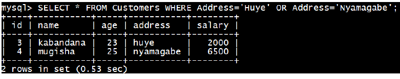
The following SQL statement selects all fields from “Customers” where address is NOT“Nyamagabe”:
ExampleSELECT * FROM “Customers” WHERE NOT Address=’Nyamagabe’;
You can also combine the AND, OR and NOT operators.
The following SQL statement selects all fields from ““Customers”” where address is
“Nyamagabe” AND address must be “Huye” OR “Nyamagabe” (use parenthesis to form
complex expressions):
Example:
SELECT * FROM “Customers” WHERE Address=’Nyamagabe’ AND (Address=’Huye’ ORAddress=’Nyamagabe’);
The following SQL statement selects all fields from “Customers” where address is NOT
“Nyamagabe” and NOT “GASABO”:
Example:SELECT * FROM “Customers” WHERE NOT Address=”Nyamagabe” AND NOT Address=”GASABO”;
Application activity 4.6:
You are given a flat database named “Library”, with a relation Book (ISBN (Text, primary
key), title (text), author (text), pages (integer), and price (integer))
i. Create this database and relation, then insert at least five records.
ii. Retrieve ISBN and price of books written by “Bigirumwami”
iii. Retrieve books whose price is between 30,000 and 200,000 Rwf
iv. Select title and pages of all books
v. Show the books that have more than 300 pages or books that cost more
than 4,000 Rwf
vi. Retrieve books written by authors whose name is started by A, B or C.
vii. Order the books ‘titles from A to Z.
viii. Retrieve top three books.
ix. Delete books which have less than 50 pagesx. Delete books written by “Kagame”.
C. Aggregate functions:
1. SQL COUNT Function- The SQL COUNT aggregate function is used to
count the number of rows in a database table.
2. SQL MAX Function- The SQL MAX aggregate function allows us to select
the highest (maximum) value for a certain column.
3. SQL MIN Function- The SQL MIN aggregate function allows us to select
the lowest (minimum) value for a certain column.
4. SQL AVG Function- The SQL AVG aggregate function selects the average
value for certain table column.
5. SQL SUM Function- The SQL SUM aggregate function allows selecting the
total for a numeric column.6. SQL COUNT Function
SQL COUNT Function is the simplest function and very useful in counting the numberof records, which are expected to be returned by a SELECT statement.
Similarly, if you want to count the number of records that meet a given criteria, it can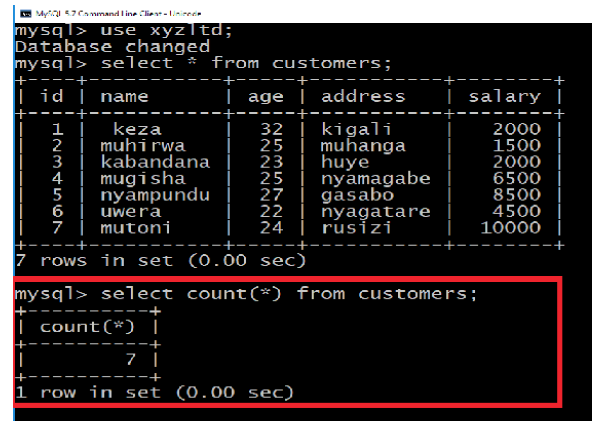
be done as follows to count records whose salary is 2000:
Notice that all the SQL queries are case insensitive, so it does not make any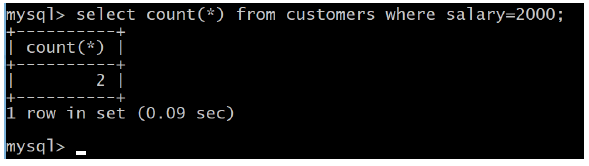
difference if you write SALARY or salary in WHERE condition.
SQL MAX Function
SQL MAX function is used to find out the record with maximum value among arecord set.
SQL MIN Function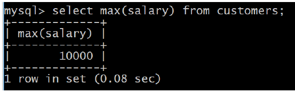
SQL MIN function is used to find out the record with minimum value among a recordset.
You can use MIN Function along with MAX function to find out minimum value as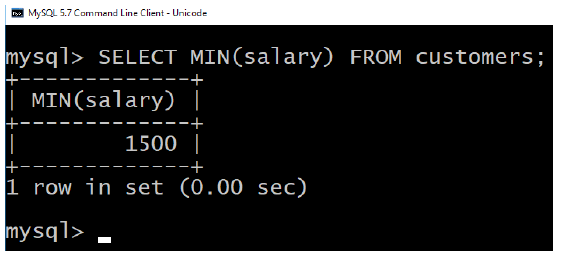
well.
SQL AVG Function
SQL AVG function is used to find out the average of a field in various records.
7. SQL SUM Function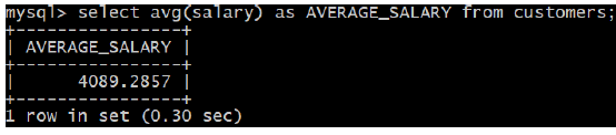
SQL SUM function is used to find out the sum of a field in various records.
Application activity 4.7: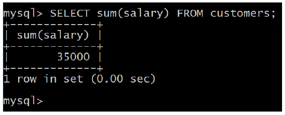
You are given a flat database named “Library”, with a relation Book (ISBN (Text,
primary key), title (text), author (text), pages (integer), and price (integer))
i. Create this database and relation, then insert at least five records.
ii. Retrieve the amount to get when all books are sold.
iii. Retrieve the most expensive book.
iv. Select the least expensive book
v. Show the total number of the books in book relation.vi. Find the average price of the books
D. String Expressions
SQL string functions are used primarily for string manipulation. The following tabledetails the important string functions:
a. CONCAT (str1,str2,...)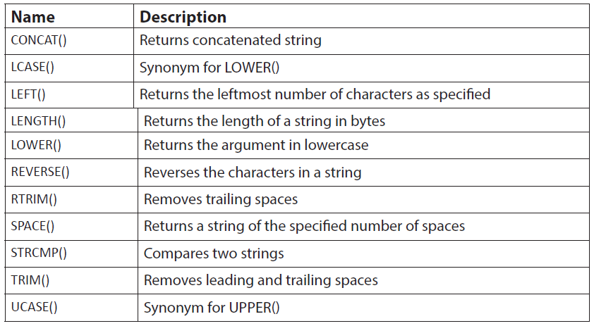
Returns the string that results from concatenating the arguments. May have one or
more arguments. If all arguments are non-binary strings, the result is a non-binary
string. If the arguments include any binary strings, the result is a binary string. A
numeric argument is converted to its equivalent binary string form; if you want toavoid that, you can use an explicit type cast, as in this example:

b. LEFT(str,len)
Returns the leftmost len characters from the string str, or NULL if any argument isNULL.
c. LENGTH (str)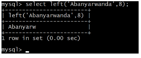
Returns the length of the string str measured in bytes. A multi-byte character counts
as multiple bytes. This means that for a string containing five two-byte characters,LENGTH
returns 10, whereas CHAR_LENGTH
d. LOWER(str)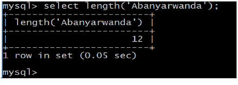
Returns the string str with all characters changed to lowercase according to thecurrent character set mapping.
e. REVERSE(str)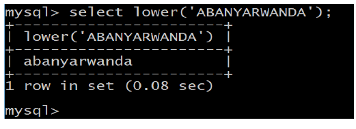
Returns the string str with the order of the characters reversed.
Application activity 4.8: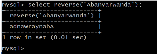
You are given a flat database named “Library”, with a relation Book (ISBN (Text,
primary key), title (text), author (text), pages (integer), and price (integer))
i. Find the length of the title of the book which has 35050115-30 as ISBN
ii. Reverse the name of the author who wrote the book “Imigenzo
n’imiziririzo ya Kinyarwanda”.
iii. Compare the names “Aloys” and “Alexis”.
iv. Change “Ndi umunyarwanda” in upper case.
v. Change “HELP EACH OTHER” in lower case
E. SQL JOINS
The SQL Joins clause is used to combine records from two or more tables in a
database. A JOIN is a mean for combining fields from two tables by using values
common to each.Consider “Customers” and orders tables as follows:
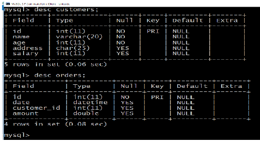
These two tables (relations) have the following records:
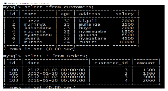
Now, let us join these two tables in our SELECT statement as follows:
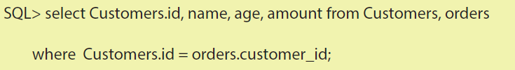
This would produce the following result:
Here, it is noticeable that the join is performed in the WHERE clause. Several operators
can be used to join tables, such as =, <, >, <>, <=, >=,! =, BETWEEN, LIKE, and NOT;
they can all be used to join tables. However, the most common operator is the equalsymbol.
SQL Join Types:
There are different types of joins available in SQL:
Inner join: returns rows when there is a match in both tables.
Left join: returns all rows from the left table, even if there are no matches in the right
table.
Right join: returns all rows from the right table, even if there are no matches in the
left table.
Full join: returns rows when there is a match in one of the tables.
Self-join: is used to join a table to itself as if the table were two tables, temporarily
renaming at least one table in the sql statement.
Cartesian join: returns the Cartesian product of the sets of records from the two ormore joined tables.
1. INNER JOIN
The most frequently used and important of the joins is the INNER JOIN. They are also
referred to as an EQUIJOIN.
The INNER JOIN creates a new result table by combining column values of two
tables (table1 and table2) based upon the join-predicate. The query compares each
row of table1 with each row of table2 to find all pairs of rows which satisfy the joinpredicate.
When the join-predicate is satisfied, column values for each matched pairof rows of A and B are combined into a result row.
The basic syntax of INNER JOIN is as follows:

2. LEFT JOIN
The SQL LEFT JOIN returns all rows from the left table, even if there are no matches
in the right table. This means that if the ON clause matches 0 (zero) records in right
table, the join will still return a row in the result, but with NULL in each column from
right table.
This means that a left join returns all the values from the left table, plus matchedvalues from the right table or NULL in case of no matching join predicate.
Syntax:The basic syntax of LEFT JOIN is as follows:

3. RIGHT JOIN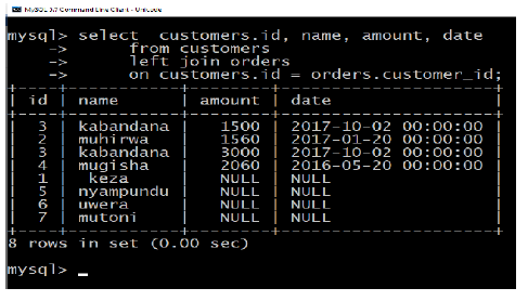
The SQL RIGHT JOIN returns all rows from the right table, even if there are no matches
in the left table. This means that if the ON clause matches 0 (zero) records in left
table, the join will still return a row in the result, but with NULL in each column from
left table.
This means that a right join returns all the values from the right table, plus matched
values from the left table or NULL in case of no matching join predicate.The basic syntax of RIGHT JOIN is as follows:

4. FULL JOIN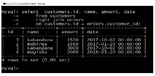
The SQL FULL JOIN combines the results of both left and right outer joins.
The joined table will contain all records from both tables, and fill in NULLs for missing
matches on either side.The basic syntax of FULL JOIN is as follows:

If your DBMS does not support FULL JOIN like MySQL does not support FULL JOIN,
then you can use UNION ALL clause to combine two JOINS as follows:
5. SELF JOIN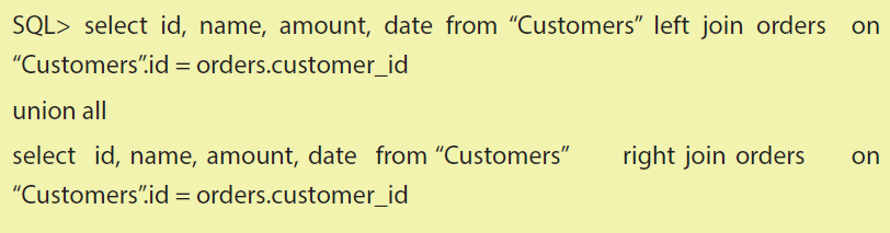
The SQL SELF JOIN is used to join a table to itself as if the table were two tables,
temporarily renaming at least one table in the SQL statement.The basic syntax of SELF JOIN is as follows:

6. CARTESIAN JOIN
The CARTESIAN JOIN or CROSS JOIN returns the Cartesian product of the sets of
records from the two or more joined tables. Thus, it equates to an inner join where
the join-condition always evaluates to True or where the join condition is absent
from the statement.The basic syntax of INNER JOIN is as follows:

F. SQL Unions Clause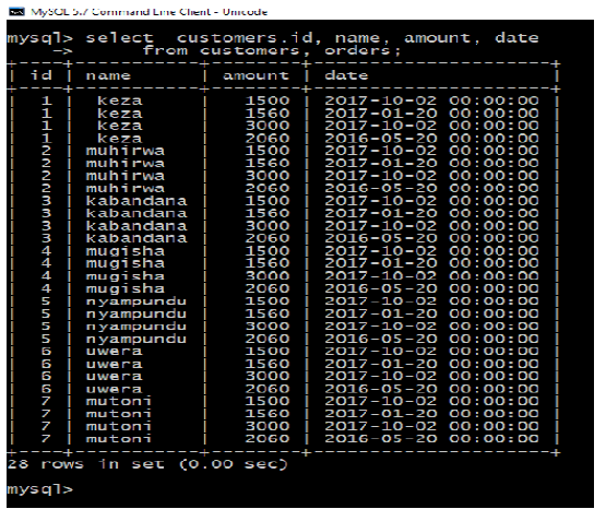
The SQL UNION clause/operator is used to combine the results of two or more
SELECT statementswithout returning any duplicate rows.
To use UNION, each SELECT must have the same number of columns selected, the
same number of column expressions, the same data type, and have them in the
same order, but they do not have to be the same length.The basic syntax of UNION is as follows:

1. The UNION ALL Clause:
The UNION ALL operator is used to combine the results of two SELECT statements
including duplicate rows. The same rules that apply to UNION apply to the UNIONALL operator.
The basic syntax of UNION ALL is as follows:
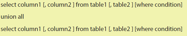
There are two other clauses (i.e., operators), which are very similar to UNION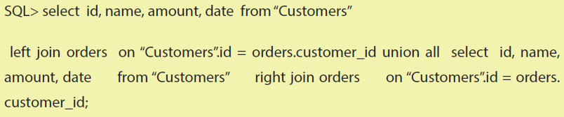
clause: SQLINTERSECT Clause: is used to combine two SELECT statements, but
returns rows only from the first SELECT statement that are identical to a row in the
second SELECT statement. SQLEXCEPT Clause: combines two SELECT statements and
returns rows from the first SELECT statement that are not returned by the second
SELECT statement.
2. INTERSECT Clause
The SQL INTERSECT clause/operator is used to combine two SELECT statements,
but returns rows only from the first SELECT statement that are identical to a row in
the second SELECT statement. This means INTERSECT returns only common rows
returned by the two SELECT statements.
Just as with the UNION operator, the same rules apply when using the INTERSECT
operator. MySQL does not support INTERSECT operatorThe basic syntax of INTERSECT is as follows:
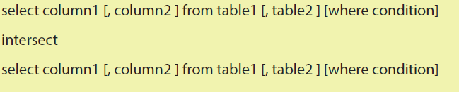
Example:
3. EXCEPT Clause
The SQL EXCEPT clause/operator is used to combine two SELECT statements and
returns rows from the first SELECT statement that are not returned by the second
SELECT statement. This means EXCEPT returns only rows, which are not available in
second SELECT statement.
Just as with the UNION operator, the same rules apply when using the EXCEPT
operator. MySQL does not support EXCEPT operator.The basic syntax of EXCEPT is as follows:
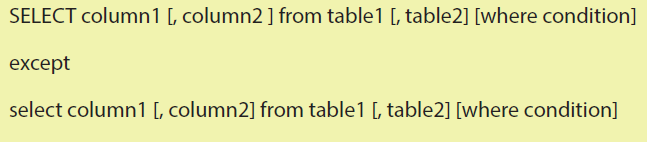
Example:
Select statement with Alias
You can rename a table or a column temporarily by giving another name known asalias.
The use of table aliases means to rename a table in a particular SQL statement. The
renaming is a temporary change and the actual table name does not change in the
database. The column aliases are used to rename a table’s columns for the purpose
of a particular SQL query.The basic syntax of table alias is as follows:

The basic syntax of column alias is as follows:


Following is the usage of column alias:

G. SQL TRUNCATE TABLE
The SQL TRUNCATE TABLE command is used to delete complete data from an
existing table.
You can also use DROP TABLE command to delete complete table but it would
remove complete table structure form the database and you would need to recreate
this table once again if you wish you store some data.The basic syntax of TRUNCATE TABLE is as follows:

Example:
H. SQL HAVING CLAUSE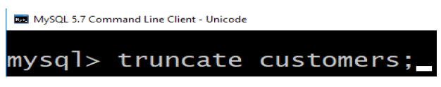
The HAVING clause enables you to specify conditions that filter which group results
appear in the final results. The WHERE clause places conditions on the selected
columns, whereas the HAVING clause places conditions on groups created by the
GROUP BY clause.The following is the position of the HAVING clause in a query:
The HAVING clause must follow the GROUP BY clause in a query and must also
precede the ORDER BY clause if used. The following is the syntax of the SELECTstatement, including the HAVING clause:
Example:
Following is the example, which would display record for which similar age countwould be more than or equal to 2:
I . SQL SUB QUERIES
A Subquery or Inner query or Nested query is a query within another SQL query and
embedded within the WHERE clause.
A subquery is used to return data that will be used in the main query as a condition
to further restrict the data to be retrieved.
Subqueries can be used with the SELECT, INSERT, UPDATE, and DELETE statements
along with the operators like =, <, >, >=, <=, IN, BETWEEN etc.
There are a few rules that subquery must follow:
* Subquery must be enclosed within parentheses.
* A subquery can have only one column in the SELECT clause, unless multiple
columns are in the main query for the subquery to compare its selected
columns.
* Subqueries that return more than one row can only be used with multiple
value operators, such as the IN operator.
* A subquery cannot be immediately enclosed in a set function.
* The BETWEEN operator cannot be used with a subquery; however, the
BETWEEN operator can be used within the subquery.
I.1. Subqueries with the SELECT Statement:Subqueries are most frequently used with the SELECT statement. The basic syntax
is as follows:
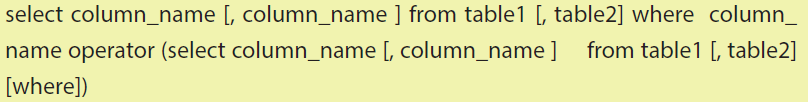
I.2. Subqueries with the INSERT Statement:
Subqueries also can be used with INSERT statements. The INSERT statement uses the
data returned from the subquery to insert into another table. The selected data inthe subquery can be modified with any of the character, date or number functions.
The basic syntax is as follows:
Example:
Consider a table “CUSTOMERS”_BKP with similar structure as “CUSTOMERS” table.
Now to copy complete “CUSTOMERS” table into “CUSTOMERS”_BKP, following is thesyntax:
I.3. Subqueries with the UPDATE Statement: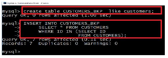
The subquery can be used in conjunction with the UPDATE statement. Either single
or multiple columns in a table can be updated when using a subquery with theUPDATE statement.
The basic syntax is as follows:
Example:
Assuming, we have “CUSTOMERS”_BKP table available which is backup of
“CUSTOMERS” table.
Following example updates SALARY by 0.25 times in “CUSTOMERS” table for all the“Customers” whose AGE is greater than or equal to 27:
I.4. Subqueries with the DELETE Statement: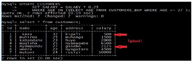
The subquery can be used in conjunction with the DELETE statement like with anyother statements mentioned above.
The basic syntax is as follows:
Example:
Assuming, we have “CUSTOMERS”_BKP table available which is backup of
“CUSTOMERS” table.
Following example deletes records from “CUSTOMERS” table for all the “Customers”whose AGE is greater than or equal to 27:
delete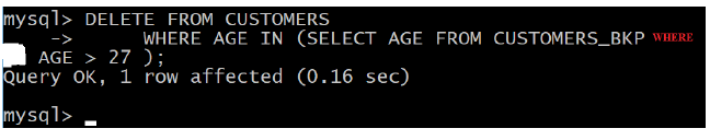
The SQL DELETE Query is used to delete the existing records from a table.
You can use WHERE clause with DELETE query to delete selected rows, otherwise all
the records would be deleted.The basic syntax of DELETE query with WHERE clause is as follows:

Following is an example, which would DELETE a customer, whose ID is 6:
If you want to DELETE all the records from “CUSTOMERS” table, you do not need to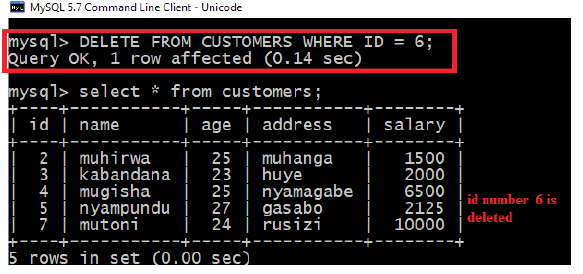
use WHERE clause and DELETE query would be as follows:
4.2.3 Data Control Language (DCL)
SQL GRANT and REVOKE commands
DCL commands are used to enforce database security in a multiple user database
environment. Two types of DCL commands are GRANT and REVOKE. Only Database
Administrator’s or owners of the database object can provide/remove privileges ona database object.
a. SQL GRANT Command
SQL GRANT is a command used to provide access or privileges on the database
objects to the users.The Syntax for the GRANT command is:
* privilege_name is the access right or privilege granted to the user. Some of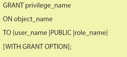
the access rights are ALL, EXECUTE, and SELECT.
* object_name is the name of an database object like TABLE, VIEW, STORED
PROC and SEQUENCE.
* user_name is the name of the user to whom an access right is being granted.
* Public is used to grant access rights to all users.
* Roles are a set of privileges grouped together.
* With grant option - allows a user to grant access rights to other users.
For Example:
GRANT SELECT ON employee TO user1; This command grants a SELECT permission
on employee table to user1.You should use the WITH GRANT option carefully
because for example if you GRANT SELECT privilege on employee table to user1
using the WITH GRANT option, then user1 can GRANT SELECT privilege on employee
table to another user, such as user2 etc. Later, if you REVOKE the SELECT privilege onemployee from user1, still user2 will have SELECT privilege on employee table.
b. SQL REVOKE Command:
The REVOKE command removes user access rights or privileges to the database
objects.The Syntax for the REVOKE command is:
For Example: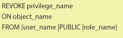
REVOKE SELECT ON employee FROM user1;This command will REVOKE a SELECT
privilege on employee table from user1.When you REVOKE SELECT privilege on a
table from a user, the user will not be able to SELECT data from that table anymore.
However, if the user has received SELECT privileges on that table from more than one
users, he/she can SELECT from that table until everyone who granted the permissionrevokes it. You cannot REVOKE privileges if they were not initially granted by you.
c. Privileges and Roles:
Privileges: Privileges defines the access rights provided to a user on a database
object. There are two types of privileges.
1. System privileges - This allows the user to CREATE, ALTER, or DROP
database objects.
2. Object privileges - This allows the user to EXECUTE, SELECT, INSERT,
UPDATE, or DELETE data from database objects to which the privilegesapply.
Application activity 4.9:
You are given a flat database named “Library”, with a relation Book (ISBN (Text,
primary key), title (text), author (text), pages (integer), and price (integer)).
i. Create student and teacher users
ii. Give student user “selection” abilities only
iii. Give all rights to user teacheriv. Revoke selection rights to students
Application activity 4.10:
XYZ Ltd is a company that focusses on finding ICT and technology related
solution to the citizens of Rwanda. It develops software and offers maintenance.
It has many competitors in Rwanda and in East Africa, but XYZ Ltd tries to be a
market winner in the region. One day, unknown person managed to have access
and enter to the XYZ Ltd systems without company’s authorization. That person
managed to change the passwords that the company used in its everyday
activities.
1. Discuss the challenges that the company should face
2. Can granting privileges help in preventing such cases? If yes, showhow. If no, explain
4.3.Database security concept
As computers need to be physically and logically protected, the database inside
needs also to be secured. There are some principles linked to databases so that
they can remain meaningful. Those principles are integrity, Availability, Privacy and
Confidentiality.
When dealing with a database belonging to an individual or an organization
(company), Some actions are done to Backup and Concurrent control for the sakeof security.
Activity 4.10:
1. What are the problems that a database can face in a computer?
2. How the security of database can be done?
3. Who is responsible of the security of a database?
4. What are the consequences that can happen when database security is
violated?
5. Discuss security measure that can be taken to keep database secure.Data integrity refers to the overall completeness, accuracy and consistency of data.
4.3.1. Integrity
There are four types of integrity:
»»Entity (or table) integrity requires that all rows in a table have a unique identifier,
known as the primary key value. Whether the primary key value can be changed,
or whether the whole row can be deleted, depends on the level of integrity
required between the primary key and any other tables.
»»Referential integrity ensures that the relationship between the primary key (in a
referenced table) and the foreign key (in each of the referencing tables) is always
maintained. The maintenance of this relationship means that:
i. A row in a referenced table cannot be deleted, nor can the primary key be
changed, if a foreign key refers to the row. For example, you cannot delete
a customer that has placed one or more orders.
ii. A row cannot be added to a referencing table if the foreign key does not
match the primary key of an existing row in the referenced table. For
example, you cannot create an order for a customer that does not exist.
»»Domain (or column) integrity specifies the set of data values that are valid for
a column and determines whether null values are allowed. Domain integrity is
enforced by validity checking and by restricting the data type, format, or range of
possible values allowed in a column.
»»User-Defined integrity: Enforces some specific business rules that do not fall into
entity, domain, or referential integrity.
4.3.2. Availability
Availability is the condition where in a given resource can be accessed by its
consumers. So in terms of databases, availability means that if a database is available,
the users of its data; that is, applications, “Customers”, and business users; can access
it. Any condition that renders the resource inaccessible causes the opposite of
availability: unavailability.
Another perspective on defining availability is the percentage of time that a system
can be used for productive work. The required availability of an application will vary
from organization to organization, within an organization from system to system,and even from user to user.
Database availability and database performance are terms that are often confused
with one another, and indeed, there are similarities between the two. The major
difference lies in the user’s ability to access the database. It is possible to access a
database suffering from poor performance, but it is not possible to access a database
that is unavailable. So, when does poor performance turn into unavailability?
If performance suffers to such a great degree that the users of the database cannot
perform their job, the database has become, for all intents and purposes, unavailable.
Nonetheless, keep in mind that availability and performance are different and must
be treated by the database administrator as separate issues; even though a severe
performance problem is a potential availability problem.
Availability comprises four distinct components, which, in combination, assure that
systems are running and business can be conducted:
Manageability: the ability to create and maintain an effective environment that
delivers service to users
Recoverability: the ability to reestablish service in the event of an error or
component failure
Reliability: the ability to deliver service at specified levels for a stated period
Serviceability: the ability to determine the existence of problems, diagnose their
cause(s), and repair the problems.
All four of these “abilities” impact the overall availability of a system, database, or
application.
4.3.3. Data Privacy
Privacy of information is extremely important in this digital age where everything is
interconnected and can be accessed and used easily. The possibilities of our private
information being extremely vulnerable are very real, which is why we require data
privacy. We can describe the concept as:
Data privacy, also known as information privacy, is the necessity to preserve and
protect any personal information, collected by any organization, from being accessed
by a third party. It is a part of Information Technology that helps an individual or an
organization determine what data within a system can be shared with others andwhich should be restricted.
What Type of data is included?
Any personal data that could be sensitive or can be used maliciously by someone
is included when considering data privacy. These data types include the following:
• Online Privacy: This includes all personal data that is given out during
online interactions. Most sites have a privacy policy regarding the use of
the data shared by users or collected from users.
• Financial Privacy: Any financial information shared online or offline is
sensitive as it can be utilized to commit fraud.
• Medical Privacy: Any details of medical treatment and history is privileged
information and cannot be disclosed to a third party. There are very
stringent laws regarding sharing of medical records.
• Residential and geographic records: sharing of address online can be a
potential risk and needs protection from unauthorized access.
• Political Privacy: this has become a growing concern that political
preferences should be privileged information.
• Problems with providing Data Security
• It is not an easy task to provide data security. Most organizations have
problems in providing proper information privacy. These problems
include:
• Difficulty in understanding and defining what is sensitive data and what
is not.
• With data growing in volume by the day, most organizations struggle
to create real-time masking facilities and security policies to efficiently
protect all the data.
• Difficulty to screen and review data from a central location with outmoded
tools and bloated databases.
Importance of Data Security
* Data security is extremely important for any individual or organization, as
theft of data, can cause huge monetary losses. Data security can help an
organization by:
• Preventing theft of data;
• Preserving data integrity;
• Containing a cost of compliance to data security requirements;• Protection of privacy.
Legal provisions for Data Security
The laws that govern data security vary across the world. Different countries and legal
systems deal with it in their way. But most laws agree that personal data is shared
and processed only for the purpose for which the information has been collected.
In Rwanda we have RURA (Rwanda Utilities Regulatory Agency) that govern datasecurity issues.
4.3.4. Confidentiality
Confidentiality refers to protecting information from being accessed by unauthorized
parties. In other words, only the people who are authorized to do so can gain access
to sensitive data. Imagine your bank records. You should be able to access them, of
course, and employees at the bank who are helping you with a transaction should
be able to access them, but no one else should.
A failure to maintain confidentiality means that someone who shouldn’t have access
has managed to get it, through intentional behavior or by accident. Such a failure of
confidentiality, commonly known as a breach, typically cannot be remedied. Once
the secret has been revealed, there’s no way to un-reveal it.
If your bank records are posted on a public website, everyone can know your bank
account number, balance, etc., and that information can’t be erased from their
minds, papers, computers, and other places. Nearly all the major security incidentsreported in the media today involve major losses of confidentiality.
a. Backup
In information technology, a backup, or the process of backing up, refers to the
copying and archiving of computer data so it may be used to restore the original
after a data loss event.
A catastrophic failure is one where a stable, secondary storage device gets corrupt.
With the storage device, all the valuable data that is stored inside is lost. We have
two different strategies to recover data from such a catastrophic failure:
* Remote backup – Here a backup copy of the database is stored at a remote
location from where it can be restored in case of a catastrophe.* Alternatively, database backups can be taken on magnetic tapes and storedSo, all that we need to do here is to take a backup of all the logs at frequent intervals
at a safer place. This backup can later be transferred onto a freshly installed
database to bring it to the point of backup. Grown-up databases are too
bulky to be frequently backed up. In such cases, we have techniques where
we can restore a database just by looking at its logs.
of time. The database can be backed up once a week, and the logs being very small
can be backed up every day or as frequently as possible.
b. Remote access
Individuals, small and big institutions/companies are using databases in their daily
businesses. Most of the time institutions have agencies spread around the country,
region or the world. Umwalimu SACCO is a saving and credit Cooperative that
helps teachers to improve their lives by getting financial loans at low interests. This
institution is having different agencies in different districts. The central agency is
located at Kigali and host the main database of all members of Umwalimu SACCO
in Rwanda. When a client goes to look for a service at an agency, the teller requests
permissions from Kigali by identifying, authenticating him/her self so that the
authorization can be granted to him/her. The whole network works in the mode of
Cleint/Server. The fact of getting connection to the server from far is what we call
“Remote Access”. Hence, the database is accessed remotely. This act requires some
security measures because otherwise anybody can disturbs the system of working
and hack the whole business system of Umwalimu SACCO.
This institution needs then to set rules and regulations to manage the remote access
to its information.
c. Concurrent control
Process of managing simultaneous operations on the database without having
them interfere with one another.
- Prevents interference when two or more users are accessing database
simultaneously and at least one is updating data.
- Although two transactions may be correct in themselves, interleaving ofoperations may produce an incorrect result.
Three examples of potential problems caused by concurrency:
• Lost update problem.
• Uncommitted dependency problem.
• Inconsistent analysis problem.
Application activity 4.11:
1. Discuss the advantages of data backup.
2. Explain the advantages of remote access to big companies.
3. Discuss the reasons why a database administrator must understand
well the concept of privacy as used in database.
4. Compare the concepts of integrity, availability and confidentiality.
Discuss what should happen when they are violated (case by case).
5. A secondary school has a Management Information System hosted on
their own server located inside their compound. All the important data
related to students, teachers, salaries, marks, library, etc. are in that
server.
One day, it happened that the Head Master finds that some students have the
lists of their marks in all courses before deliberation. He investigated and found
that the students did not get marks from any teachers or administrative/technical
staff of the school.
• In groups, discuss what should happened in the server of the school
• Is data privacy assured in that server?
• What are the measures that the school has to put in place to protect
their data.
4.3.5. Database threats
Activity 4.11
i. From what you have seen in computer security, what are the possible
threats of computers?
ii. What do you do in case you realize that there are threats for your
computer system?iii. Can database be attacked by hackers?
Threat is any situation or event, whether intentional or unintentional, that will
adversely affect a system and consequently an organization.
Threats to databases result in the loss or degradation of some or all of the followingsecurity goals: integrity, availability, and confidentiality.
• Loss of integrity: Database integrity refers to the requirement that
information be protected from improper modification. Modification of
data includes creation, insertion, modification, changing the status of
data, and deletion. Integrity is lost if unauthorized changes are made to
the data by either intentional or accidental acts. If the loss of system or
data integrity is not corrected, continued use of the contaminated system
or corrupted data could result in inaccuracy, fraud, or erroneous decisions.
• Loss of availability: Database availability refers to making objects
available to a human user or a program to which they have a legitimate
right.
• Loss of confidentiality: Database confidentiality refers to the protection
of data from unauthorized disclosure. The impact of unauthorized
disclosure of confidential information can range from violation of the
Data Privacy Act to the jeopardization of national security. Unauthorized,
unanticipated, or unintentional disclosure could result in loss of public
confidence, embarrassment, or legal action against the organization.
In other words we can say that database threats can appear in form of unauthorizedusers, physical damage, and Data corruption.
a. Database protectionThe protection of a database can be done through access control and data encryption
Access control
- Based on the granting and revoking of privileges.
- A privilege allows a user to create or access (that is read, write, or modify)
some database object (such as a relation, view, and index) or to run certain
DBMS utilities.
- Privileges are granted to users to accomplish the tasks required for theirjobs.
Data encryption
- The encoding of the data by a special algorithm that renders the data
- unreadable by any program without the decryption key.
Application activity 4.12:
You are tasked to design a database of your school. Discuss the steps you will
follow to come up with genuine product by keeping in mind the data securityand the protection of the database against the potential threats.
4.3.6. Database planning and designing
Activity 4.12
1. Discuss the pillars of database design
2. Why is database planning necessary?
3. Discuss activities involved in database planning.
Before planning, designing and managing a database, first it is created. Its creation
goes through defined steps known as Database System Development Lifecycle.Those steps are:
• Database planning
• System definition
• Requirements collection and analysis
• Database design
• DBMS selection (optional)
• Prototyping (optional)
• Implementation
• Data conversion and loading
• Testing• Operational maintenance
A. Database Planning
Management activities that allow stages of database system development
lifecycle to be realized as efficiently and effectively as possible.
◊ Must be integrated with overall information system strategy of the
organization.
◊ Database planning should also include development of standards that
govern:
• How data will be collected,
• How the format should be specified,
• What necessary documentation will be needed,
• How design and implementation should proceed.
Database Planning – Mission Statement:
• Mission statement for the database project defines major aims of database
application.
• Those driving database project normally define the mission statement.
• Mission statement helps clarify purpose of the database project and
provides clearer path towards the efficient and effective creation of
required database system.
Database Planning – Mission Objectives:
• Once mission statement is defined, mission objectives are defined.
• Each objective should identify a particular task that the database must
support.
• May be accompanied by some additional information that specifies the
work to be done, the resources with which to do it, and the money to payfor it all.
System Definition
• Database application may have one or more user views.
• Identifying user views helps ensure that no major users of the database
are forgotten when developing requirements for new system.
• User views also help in development of complex database system allowing
requirements to be broken down into manageable pieces.
Requirements Collection and Analysis
• Process of collecting and analysing information about the part of
organization to be supported by the database system, and using this
information to identify users’ requirements of new system.
• Information is gathered for each major user view including:
* a description of data used or generated;
* details of how data is to be used/generated;
* any additional requirements for new database system.
* Information is analyzed to identify requirements to be included in newdatabase system. Described in the requirements specification.
• Another important activity is deciding how to manage the requirementsfor a database system with multiple user views.
Three main approaches:
• centralized approach;
• view integration approach;
• combination of both approaches(hybrid).
Centralized approach
• Requirements for each user view are merged into a single set of
requirements.
• A data model is created representing all user views during the databasedesign stage.
View integration approach
* Requirements for each user view remain as separate lists.
* Data models representing each user view are created and then merged
later during the database design stage.
◊ Data model representing single user view (or a subset of all user views) is
called a local data model.
◊ Each model includes diagrams and documentation describing requirements
for one or more but not all user views of database.
◊ Local data models are then merged at a later stage during database design
to produce a global data model, which represents all user views for thedatabase.
B. Database Design
In every institution, there is a process of creating a design for a database that will
support the enterprise’s mission statement and mission objectives for the required
database system.
The main approaches include:
◊ Top-down or Entity-Relationship Modelling◊ Bottom-up or Normalisation
Top-down approach
* Starts with high-level entities and relationships with successive
refinement to identify more detailed data model.* Suitable for complex databases.
Bottom-up approach
* Starts with a finite set of attributes and follows a set of rules to group
attributes into relations that represent entities and relationships.* Suitable for small number of attributes.
The main purposes of data modeling include:
* to assist in understanding the meaning (semantics) of the data;
* to facilitate communication about the information requirements.
* Building data model requires answering questions about entities,relationships, and attributes.
There are three phases of database design: Conceptual database design, Logical
database design and Physical database design.
Conceptual Database Design:
* Process of constructing a model of the data used in an enterprise,
independent of all physical considerations.
* Data model is built using the information in users’ requirements
specification.
* Conceptual data model is source of information for logical design phase.
Logical Database Design:
* Process of constructing a model of the data used in an enterprise based
on a specific data model (e.g. relational), but independent of a particular
DBMS and other physical considerations.
* Conceptual data model is refined and mapped on to a physical data
model.
Physical Database Design:
* Process of producing a description of the database implementation on
secondary storage.
* Describes base relations, file organizations, and indexes used to achieve
efficient access to data. Also describes any associated integrity constraints
and security measures.* Tailored to a specific DBMS.
DBMS Selection:
The selection of an appropriate DBMS to support the database system follows these
steps: define Terms of Reference of study; shortlist two or three products; evaluateproducts and Recommend selection and produce report.
END UNIT ASSESSMENT
Part I: Relational algebra and SQL statements
1. 1. A company organizes its activities in projects. Products that are used in
the projects are bought from suppliers. This is described in a database with
the following schema: Projects(projNbr, name, city) Products(prodNbr,
name, color) Suppliers(supplNbr, name, city) Deliveries(supplNbr, prodNbr,
projNbr, number). Write relational algebra expressions that give the
following information:
a. All information about all projects.
b. All information about all projects in Kigali.
c. The supplier numbers of the suppliers that deliver to project number 123.
d. The product numbers of products that are delivered by suppliers in Kigali.
e. All pairs of product numbers such that at least one supplier delivers
both products.
4. The following relations keep track of airline flight information:
Flights(flno: integer, from: string, to: string, distance: integer, departs: time,
arrives: time, price: real) Aircraft(aid: integer, aname: string, cruisingrange: integer)
Certified(eid: integer, aid: integer) Employees(eid: integer, ename: string, salary:
integer)
Note that the Employees relation describes pilots and other kinds of employees as
well; every pilot is certified for some aircraft, and only pilots are certified to fly. Write
each of the following queries in SQL.
i. Find the names of aircraft such that all pilots certified to operate them have
salaries more than $80,000.
ii. For each pilot who is certified for more than three aircraft, find the eid and
the maximum cruising range of the aircraft for which she or he is certified.
iii. Find the names of pilots whose salary is less than the price of the cheapest
route from Kigali to New York.
iv. For all aircraft with cruising range over 1000 miles, find the name of the
aircraft and the average salary of all pilots certified for this aircraft.
v. Find the names of pilots certified for some Boeing aircraft.
vi. Find the aids of all aircraft that can be used on routes from Kigali to London.
vii. Identify the routes that can be piloted by every pilot who makes more than
$100,000.
viii. Print the names of pilots who can operate planes with cruising range
greater than 3000 Km but are not certified on any Boeing aircraft.
ix. A customer wants to travel from Kigali to New York with no more than
two changes of flight. List the choice of departure times from Kigali if the
customer wants to arrive in New York by 6 p.m.
x. Compute the difference between the average salary of a pilot and the
average salary of all employees (including pilots).
xi. Print the name and salary of every non pilot whose salary is more than the
average salary for pilots.
xii. Print the names of employees who are certified only on aircrafts with
cruising range longer than 1000 Km.
xiii. Print the names of employees who are certified only on aircrafts with
cruising range longer than 1000 Km, but on at least two such aircrafts.
xiv. Print the names of employees who are certified only on aircrafts with
cruising range longer than 1000 Km and who are certified on some Boeingaircraft.
Part II: Database projects
1. Consider the following relations:
Student (snum: integer, sname: string, major: string, level: string, age: integer)
Class (name: string, meets at: string, room: string, fid: integer)
Enrolled (snum: integer, cname: string)
Faculty (fid: integer, fname: string, deptid: integer)
The meaning of these relations is straightforward; for example, Enrolled has one
record per student-class pair such that the student is enrolled in the class. Level is a
two character code with 4 different values (example: Junior: A Level etc)
Write the following queries in SQL. No duplicates should be printed in any of the
answers.
i. Find the names of all Juniors (level = A Level) who are enrolled in a class
taught by Prof. Kwizera
ii. ii. Find the names of all classes that either meet in room R128 or have five or
more Students enrolled.
iii. Find the names of all students who are enrolled in two classes that meet at
the same time.
iv. Find the names of faculty members who teach in every room in which some
class is taught.
v. Find the names of faculty members for whom the combined enrollment ofthe courses that they teach is less than five.
2. The following relations keep track of airline flight information:
Flights (no: integer, from: string, to: string, distance: integer, Departs: time, arrives:
time, price: real) Aircraft (aid: integer, aname: string, cruisingrange: integer)
Certified (eid: integer, aid: integer)
Employees (eid: integer, ename: string, salary: integer)
Note that the Employees relation describes pilots and other kinds of employees as
well; every pilot is certified for some aircraft, and only pilots are certified to fly.
Write each of the following queries in SQL:
i. Find the names of aircraft such that all pilots certified to operate them have
salaries more than Rwf.80, 000.
ii. For each pilot who is certified for more than three aircrafts, find the eid and
the maximum cruisingrange of the aircraft for which she or he is certified.
iii. Find the names of pilots whose salary is less than the price of the cheapest
route from Kigali to Nairobi.
iv. For all aircraft with cruisingrange over 1000 Kms,. Find the name of the
aircraft and the average salary of all pilots certified for this aircraft.
v. Find the names of pilots certified for some Boeing aircraft.
vi. Find the aids of all aircraft that can be used on routes from Rusizi to Kigali.
3. Consider the following database of student enrollment incourses & books adopted for each course.
STUDENT (regno: string, name: string, major: string, bdate:date)
COURSE (course #:int, cname:string, dept:string)
ENROLL ( regno:string, course#:int, sem:int, marks:int)
BOOK _ ADOPTION (course# :int, sem:int, book-ISBN:int)
TEXT (book-ISBN:int, book-title:string, publisher:string, author:string)
i. Create the above tables by properly specifying the primary keys and the
foreign keys.
ii. Enter at least five records for each relation.
iii. Demonstrate how you add a new text book to the database and make this
book be adopted by some department.
iv. Produce a list of text books (include Course #, Book-ISBN, Book-title) in the
alphabetical order for courses offered by the ‘CS’ department that use more
than two books.
v. List any department that has all its adopted books published by a specific
publisher.
vi. Generate suitable reports.vii. Create suitable front end for querying and displaying the results.
4. The following tables are maintained by a book dealer.
AUTHOR (author-id:int, name:string, city:string, country:string)
PUBLISHER (publisher-id:int, name:string, city:string, country:string)
CATALOG (book-id:int, title:string, author-id:int, publisher-id:int, category-id:int,
year:int, price:int)
CATEGORY (category-id:int, description:string)
ORDER-DETAILS (order-no:int, book-id:int, quantity:int)
i. Create the above tables by properly specifying the primary keys and the
foreign keys.
ii. Enter at least five records for each relation.
iii. Give the details of the authors who have 2 or more books in the catalog and
the price of the books is greater than the average price of the books in the
catalog and the year of publication is after 2000.
iv. Find the author of the book which has maximum sales.
v. Demonstrate how you increase the price of books published by a specific
publisher by 10%.
vi. Generate suitable reports.vii. Create suitable front end for querying and displaying the results.
5. Consider the following database for a banking enterprise
BRANCH(branch-name:string, branch-city:string, assets:real)
ACCOUNT(accno:int, branch-name:string, balance:real)
DEPOSITOR(customer-name:string, accno:int)
CUSTOMER(customer-name:string, customer-street:string, customer-city:string)
LOAN(loan-number:int, branch-name:string, amount:real)
BORROWER(customer-name:string, loan-number:int)
i. Create the above tables by properly specifying the primary keys and the
foreign keys
ii. Enter at least five records for each relation
iii. Find all the “Customers” who have at least two accounts at the Main branch.
iv. Find all the “Customers” who have an account at all the branches located in
a specific city.
v. Demonstrate how you delete all account records at every branch located
in a specific city.
vi. Generate suitable reports.
vii. Create suitable front end for querying and displaying the results.
6. XYZ high school’s database has the following information:
i. Professors have an SSN, a name, an age, a rank, and a research specialty.
Projects have a project number, a sponsor name (e.g., USAID), a starting
date, an ending date, and a budget.
ii. Graduate students have an SSN, a name, an age, and a degree program
(e.g., Bachelor’s or Masters..).
iii. Each project is managed by one professor (known as the project’s principal
investigator).
iv. Each project is worked on by one or more professors (known as the project’s
co-investigators).
v. Professors can manage and/or work on multiple projects.
vi. Each project is worked on by one or more graduate students (known as the
project’s research assistants).
vii. When graduate students work on a project, a professor must supervise their
work on the project.
viii. Graduate students can work on multiple projects, in which case they
will have a (potentially different) supervisor for each one.
ix. Departments have a department number, a department name, and a main
office.
x. Departments have a professor (known as the chairman) who runs the
department.
xi. Professors work in one or more departments, and for each department that
they work in, a time percentage is associated with their job.
Graduate students have one major department in which they are working on their
degree. Each graduate student has another, more senior graduate student (known
as a student advisor) who advises him or her on what courses to take.
i. Design and draw an ERD that captures the information about the XYZ High
school. Use only the basic ER model here; that is, entities, relationships, and
attributes. Be sure to indicate any key and participation constraints.
ii. Use SQL statement to computerize the above ERD.
iii. Use your favorite programming language and design front end to interactwith your back end (database).
Part III: Database security
1. Explain the following terms as to database security:
i. Threat
ii. Availability
iii. Confidentiality
iv. Privacy
v. Integrity
2. Discuss the role of backup in database field.
3. In your school, find and explain the possible security issues that can harm
your database.
4. Database security is a big concern. Discuss the measures you can adopt tokeep your database secure.
UNIT 5: ARRAYS, FUNCTIONS AND PROCEDURES IN VISUAL BASIC
Key Unit Competency: Use array, functions and procedures in Visual Basic program.
Learning objectives:
•Identify the importance of using array in the program
•Identify the role of using each category of the function in the program
•Give the syntax and step to write a function
•Differentiate Inbuilt function from user-defined function and their usage
•Design and write a Visual Basic program using an array
•Design and write a Visual Basic Program using a user defined and in-built functions
Introductory activity
In one family, a mother has a culture of storing daily expenses for each day of the year; every day she records daily expenses which means 365 times per year.
Answer the following questions:
1. What do you think about 365 times of records per year in terms of programming data storage?
2. What could be the best way of doing it much better?
3. Design a VB interface which can allow her to input date/day, Expense designation, Amount, Submit, Update, Delete and Search buttons.
4. Write a VB program using a functions and procedures which receives marks 35 students in S5 Computer Science and Mathematics where by marks in 10 subjects will be entered, the program should calculate and display the average and percentage got by each student and then generates all students whom their performance is above class average.
Learning activity 5.1.
Observe and analyze the two tables below and then answer on the following questions:

Q1. Give the difference between the way data are stored in Table A and Table B
Q2. Declare variables and keep the data for both Tables
Q3.Discuss what would happen if you have to records 500 Students Names? Is it a challenge? If yes discuss what could be the best solution?
An array is a list of variables with the same data type and name. When we work with a single item, we only need to use one variable. However, if we have a list of items which are of similar type to deal with, we need to declare an array of variables instead of using a variable for each item.
By using an array, you can refer a list of values by the same name, and use a number that’s called an index or subscript to identify an individual element based on its position in the array. The indexes of an array range from zero to a number one less than the total number of elements in the array. When you use Visual Basic syntax to define the size of an array, you specify its highest index, not the total number of elements in the array.
a. Dimension of an Array
An array can be one dimensional or multidimensional. One dimensional array is like a list of items or a table that consists of one row of items or one column of items.

Example: If we need to record one hundred names, it is difficulty to declare 100 different names; this is a waste of time and efforts. So, instead of declaring one hundred different variables, we need to declare only one array. We differentiate each item in the array by using subscript, the index value of each item, for example name(1), name(2),name(3) .......etc. , makes declaring variables more streamline.
A two dimensional array is a table of items that made of rows and columns. The format for a one dimensional array is ArrayName(x), the format for a two dimensional array is ArrayName(x,y) and a three dimensional array is ArrayName(x,y,z) .

Example: A two dimensional array can be considered as a table, which will have x number of rows and y number of columns. Normally it is sufficient to use one dimensional and two dimensional arrays, you only need to use higher dimensional arrays if you need to deal with more complex problems.
b.Declaring Arrays
We can use Public or Dim statement to declare an array just as the way we declare a single variable. The Public statement declares an array that can be used throughout an application while the Dim statement declares an array that could be used only in a local procedure.
b.1. The general format to declare a one dimensional array
Dim arrayName(subs) as dataType where subs indicates the last subscript in the array.
Example
Dim StudName(5) as String
The above statement will declare an array that consists of 5 elements starting from
StudName (1) to StudName (5).
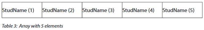
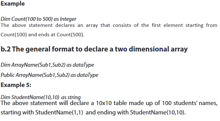
Application activity 5.1
1. Differentiate a one dimensional array from a two dimensional array
2. Declare both one dimensional and two dimensional arrays which can keep 100
5.1.2. Arrays initialization and accessing elements of an array
Learning activity 5.2.
1. Write a VB program that initializes your First name, Last name, age, combination and level of studies
2. Having an array Num already initialized with 10 numbers calculate the sum of the first and last element.
3. Discuss the way you think elements of an array can be accessed?
When creating an array, each item of the series is referred to as a member of the array. Once the array variable has been declared, each one of its members is initialized with a 0 value. Most, if not all of the time, you will need to change the value of each member to a value of your choice. This is referred to as initializing the array. To initialize an array, you can access each one of its members and assign it a desired but appropriate value.
In mathematics, if you create a series of values as X1, X2, X3, X4, and X5, each member of this series can be identified by its subscript number. In this case the subscripts are 1, 2, 3, 4, and 5. This subscript number is also called an index. In the case of an array also, each member can be referred to by an incremental number called an index. A VB array is zero-based which means that the first member of the series has an index of 0, the second has an index of 1. In math, the series would be represented as X0, X1, X2, X3, and X4. In VB, the index of a member of an array is written in its own parentheses. This is the notation you would use to locate each member. One of the actions you can take would consist of assigning it a value or array initialization. Below are some examples:
a. General syntax of array initializationa.
1. One dimensional array initialization

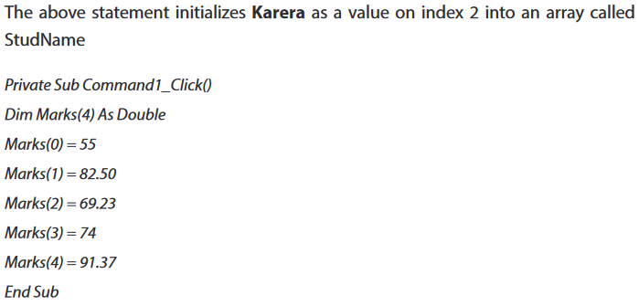
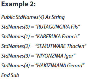
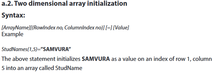
b. Accessing elements of an array
Once an array has been initialized, that is, once it holds the necessary values, you can access and use these values. The main technique used to use an array consists of accessing each member or the necessary member based on its index. Remember that an array is zero-based.
You can access the first member using an index of 0. The second member has an index of 1, and so on. Here are some examples: print function or list box can be used to access elements of an array.
Note: The two ways for accessing elements of an array are not excessive.
Syntax:
1. [Print][variableName] or
2. [ListName.AddItem] [VariableName]
You can give an example like this: Suppose an array declared as Dim Marks(4) As Double

a. With one dimensional array
Program example 1

Program example 2
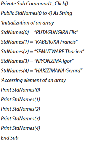
b.With two dimensional array
Program example 1
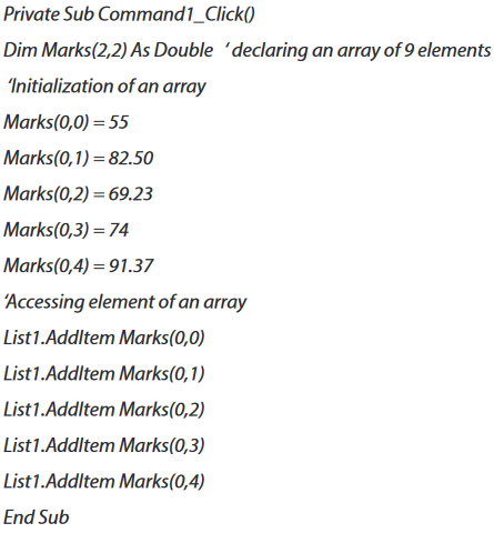
Program example 2
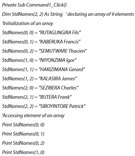

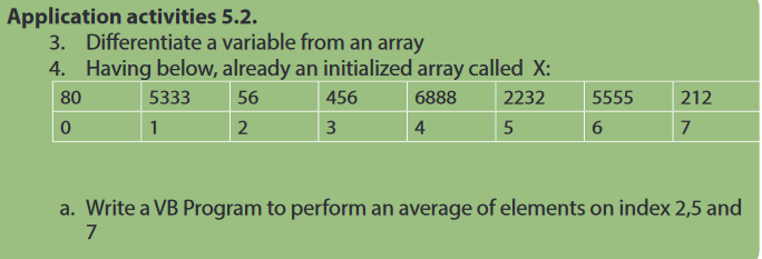
5.1.3. Entering and displaying arrays elements
Learning activity 5.3.
1. Discuss different types of controls and functions that can be used to input and to display elements of an array
The program accepts data entry through an input box and displays the entries in the form itself. As you can see, this program will only allow a user to enter student’s marks each time a user clicks on the start button.
a. Entering arrays elements
Examples
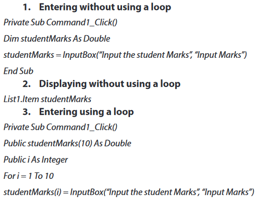
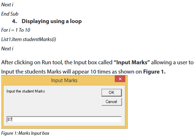
b.Displaying arrays elements
An array student Marks has been already initialized, the next step will be to display its elements using a loop.

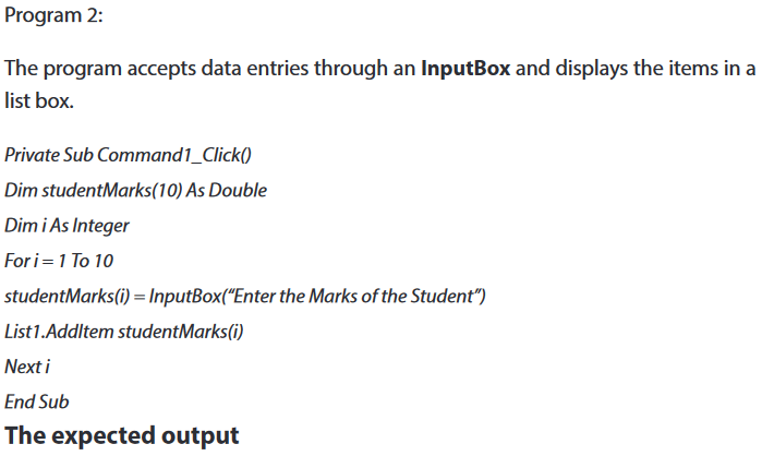

.Application activities 5.3.
1. Write a VB program which allow a user to Input 10 elements of an array and then displays even and odd numbers separately.
5.2. FUNCTIONS IN VB
Functions are “self-contained” modules of code that accomplish a specific task. Functions usually “take in” data, process it, and “return” a result. Once a function is written, it can be used over and over and over again. Functions can be “called” from the inside of other functions.
You can define a function in a module, class, or structure. It is public by default, which means you can call it from anywhere in your application that has access to the module, class, or structure in which you defined it.
A function can take arguments, such as constants, variables, or expressions, which are passed to it by the calling code.
There are two basic types of functions. Built-in functions and user defined ones. The built-in functions are part of the Visual Basic language. There are various mathematical, string or conversion functions.
5.2. 1 Built-in Functions
Learning activity 5.4.
1. Discuss the importance of using functions use in programming context
The built-in functions are functions which are automatically declared by the compiler, and associated with a built-in function identifier.
a. MsgBox
The objective of MsgBox is to produce a pop-up message box that prompt the user to click on a command button before he /she can continues. This format is as follows:
yourMsg = MsgBox(Prompt, Style Value, Title)
The first argument, Prompt, will display the message in the message box. The Style Value will determine what type of command buttons appear on the message box, please refer Table1 for types of command button displayed. The Title argument will display the title of the message board.
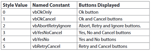
We can use named constant in place of integers for the second argument to make
the programs more readable. In fact, VB6 will automatically shows up a list of names constant where you can select one of them.
Example 1: yourMsg=MsgBox( “Click OK to Proceed”, 1, “Startup Menu”) and yourMsg=Msg(“Click OK to Proceed”. vbOkCancel,”Startup Menu”) are the same. Your Msg is a variable that holds values that are returned by the MsgBox
Table 2: Return Values and Command Buttons
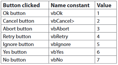
The codes for the test button see Figure 4
Private Sub Test_Click()
Dim testmsg As Integer

When the user clicks on the test button, the image like the one shown in Figure 4 will appear. As the user clicks on the OK button, the message “Testing successful” will be displayed and when he/she clicks on the Cancel button, the message “Testing fail” will be displayed.
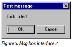
a.3. Icon besides the message
To make the message box looks more sophisticated, you can add an icon besides the message. There are four types of icons available in VB as shown in Table 5.
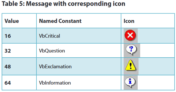
Example 3
You draw the same Interface as in example 2 but modify the codes as follows:
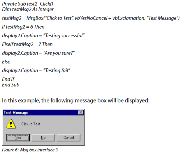
b.The InputBox
An InputBox
myMessage is a variant data type but typically it is declared as string, which accept the message input by the users. The arguments are explained as follows:
•Prompt: The message displayed normally as a question asked.
•Title: The title of the Input Box.
•Default-text: The default text that appears in the input field where users can use it as his intended input or he may change to the message he wish to key in.
•X-position and y-position: the position or the coordinate of the input box. Below is an example of an input box
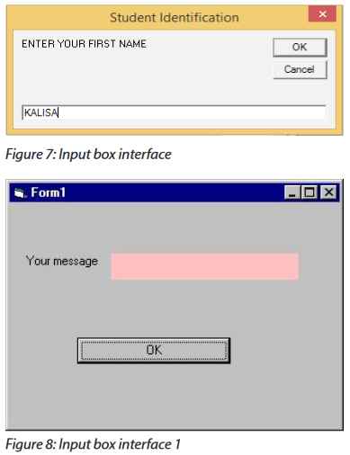
The procedure for the OK button

When a user click the OK button, the input box as shown in Figure 7 will appear. After user entering the message and click OK, the message will be displayed on the caption, if he/she clicks Cancel, “No message” will be displayed.
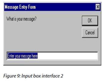
c. String function
In this lesson, we will learn how to use some of the string manipulation function such as Len, Right, Left, Mid, Trim, Ltrim, Rtrim, Ucase, Lcase, Instr, Val, Str ,Chr and Asc.
c. 1 The Len Function
The length function returns an integer value which is the length of a phrase or a sentence, including the empty spaces.

The above example will produce the output 1, 4, 8. The reason why the last value is 8 is because z# is a double precision number and so it is allocated more memory spaces.
c. 2 The Right Function
The Right function extracts the right portion of a phrase. The format is
Right (“Phrase”, n)
Where n is the starting position from the right of the phrase where the portion of the phrase is going to be extracted.
Example
Right(“Visual Basic”, 4) = asic
c. 3 The Left Function
The Left$ function extract the left portion of a phrase. The format is
Left(“Phrase”, n)
Where n is the starting position from the left of the phase where the portion of the phrase is going to be extracted.
Example
Left (“Visual Basic”, 4) = Visu
c. 4 The Ltrim Function
The Ltrim function trims the empty spaces of the left portion of the phrase. The format is
Ltrim(“Phrase”)
Example
Ltrim (“Visual Basic”, 4)= Visual basic
c. 5 The Rtrim Function
The Rtrim function trims the empty spaces of the right portion of the phrase. The format is
Rtrim(“Phrase”)
Example:
Rtrim (“Visual Basic”, 4) = Visual basic
c. 6 The Trim function
The Trim function trims the empty spaces on both side of the phrase. The format is
Trim(“Phrase”)
Example
Trim (“ Visual Basic ”) = Visual basic
c. 7 The Mid Function
The Mid function extracts a substring from the original phrase or string. It takes the following format:
Mid(phrase, position, n)
Where position is the starting position of the phrase from which the extraction process will start and n is the number of characters to be extracted.
Example
Mid(“Visual Basic”, 3, 6) = ual Bas
c. 8 The InStr function
The InStr function looks for a phrase that is embedded within the original phrase and returns the starting position of the embedded phrase. The format is
Instr (n, original phase, embedded phrase)
Where n is the position where the Instr function will begin to look for the embedded phrase.
Example
Instr(1, “Visual Basic”,” Basic”)=8
c. 9 The Ucase and the Lcase functions
The Ucase function converts all the characters of a string to capital letters. On the other hand, the Lcase function converts all the characters of a string to small letters.
Example
Ucase(“Visual Basic”) =VISUAL BASICLcase(“Visual Basic”) =visual basic
c. 10 The Str and Val functions
The Str is the function that converts a number to a string while the Val function converts a string to a number. The two functions are important when we need to perform mathematical operations.
c. 11 The Chr and the Asc functions
The Chr function returns the string that corresponds to an ASCII code while the Ascfunction converts an ASCII character or symbol to the corresponding ASCII code. ASCII stands for “American Standard Code for Information Interchange”. Altogether there are 255 ASCII codes and as many ASCII characters. Some of the characters may not be displayed as they may represent some actions such as the pressing of a key or produce a beep sound.
The format of the Chr function is:
Chr(charcode)
and the format of the Asc function is:
Asc(Character)
The following are some examples:
Chr(65)=A, Chr(122)=z, Chr(37)=% , Asc(“B”)=66, Asc(“&”)=38
d.The mathematical functions
The mathematical functions are very useful and important in programming because very often we need to deal with mathematical concepts in programming such as chance and probability, variables, mathematical logics, calculations, coordinates, time intervals and etc. The common mathematical functions in Visual Basic are Rnd, Sqr, Int, Abs, Exp, Log, Sin, Cos, Tan , Atn, Fix and Round.
a. Int is the function that converts a number into an integer by truncating its decimal part and the resulting integer is the largest integer that is smaller than the number. For example, Int(2.4)=2, Int(4.8)=4, Int(-4.6)= -5, Int(0.032)=0 and so on.
b. Sqr is the function that computes the square root of a number. For example, Sqr(4)=2, Sqr(9)=2 and etc.
c. Abs is the function that returns the absolute value of a number. So Abs(-8) = 8 and Abs(8)= 8.
d. Exp of a number x is the value of ex.
For example, Exp(1)=e1 = 2.7182818284590
e. Fix and Int are the same if the number is a positive number as both truncate the decimal part of the number and return an integer. However, when the number is negative, it will return the smallest integer that is larger than the number.
For example, Fix(-6.34)= -6 while Int(-6.34)=-7.
f. Round is the function that rounds up a number to a certain number of decimal places. The Format is Round (n, m) which means to round a number n to m decimal places.
Example
Round (7.2567, 2) =7.26
g. Log is the function that returns the natural Logarithm of a number.
Example
Log (10)= 2.302585
h. Sin is the function that returns the natural Sinus of a number.
Example
Sin(10)= -0,544021
i. Tan is the function that returns the natural Tangent of a number.
For example
Tan(10)= 0,6403608
j. Cos is the function that returns the natural Cosinus of a number.
Example
Cos(10)= -0,839071
e. Graphical methods (Line, Circle and Rectangle)
e. 1 Drawing lines
The Line method lets you draw lines in Visual Basic 6. You need to specify the starting point and the finishing point of the line in the argument. You may also specify the color of the line. This is optional, though.
i. A simple line
The following code example shows how to draw a simple line using the Line method.
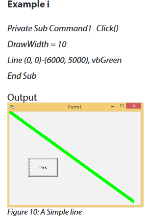
ii. A line with drawing styles Form’s Draw
Style property lets you draw lines using a particular style. The constant values of the DrawStyle property are 0 (vbSolid), 1 (vbDash), 2 (vbDot), 3 (vbDashDot, 4 (vbDashDotDot), 5 (vbTransparent) and 6 (vbInsideSolid). The default value is 0, vbSolid. You may use the numeric constant or the symbolic constant such as vbSolid, vbDash etc to change drawing styles in your code.
NOTE: The Draw Style property does not work if the value of Draw Width is other than 1.
Example
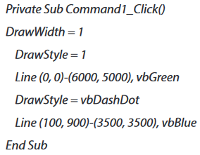

e. 2 Drawing circles
You can draw a circle using the Circle method in Visual Basic 6. You may also use the Circle method to draw different geometric shapes such as ellipses, arcs etc. You need to specify the circle’s center and radius values to draw a circle using the Circle method.
i. A simple circle
The following code draws a simple circle using the Circle method in Visual Basic 6.
Example

In the above code, (2500, 2500) is the circle’s center, and the radius value is 2000. The color constant ‘vbBlue is an optional argument.

ii. A circle filled with color
The following code example shows how to fill a circle with color in Visual Basic 6.
Example

e. 3 Rectangle
The Line method can be used to draw different geometric shapes such as rectangle, triangle etc. The following example shows you how to draw a rectangle using the Line method in Visual Basic 6.
Example e.3
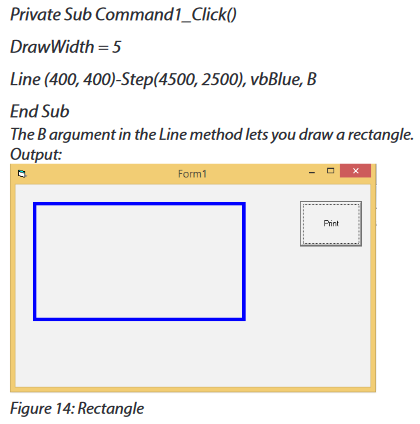
f. Format function
Formatting output is an important part of programming so that the visual interface can be presented clearly to the users. Data in the previous lesson were presented fairly systematically through the use of commas and some of the functions like Int, Fix and Round. However, to better present the output, we can use a number of formatting functions in Visual Basic. The three most common formatting functions in VB are Tab, Space, and Format
f. 1. The Tab function
The syntax of a Tab function is Tab
; x
The item x will be displayed at a position that is n spaces from the left border of the output form. There must be a semicolon in between Tab and the items you intend to display (VB will actually do it for you automatically).
Example f.1.
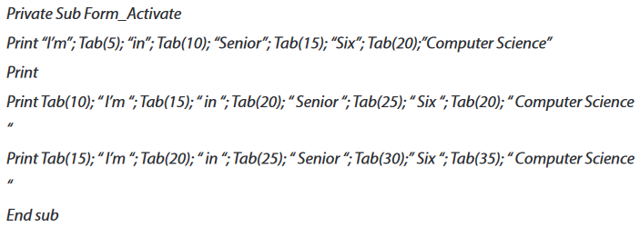
f. 2. The Space function
The Space function is very closely linked to the Tab function. However, there is a minor difference. While Tab
Example f.2.
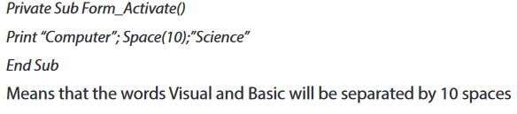
f. 3. The Format function
The Format function is a very powerful formatting function which can display the numeric values in various forms. There are two types of Format function, one of them is the built-in or predefined format while another one can be defined by the users.
(a) The syntax of the predefined Format function is
Format (n, “style argument”) where n is a number and the list of style arguments is given in Table 6.
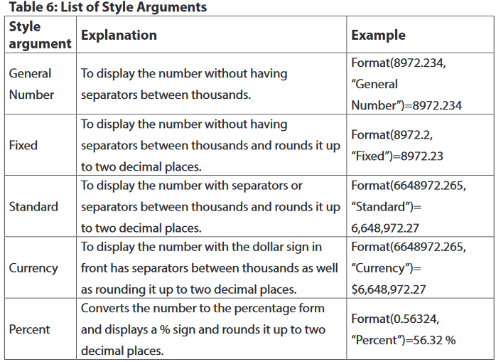
Example f.2.
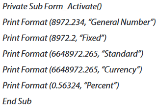
Application activity 5.4.
Write a VB program using Input box that accept a string value from the keyboard and then convert it into an integer value, performs and displays its sinus, cosinus and tangent
5.2.2. User Defined functions
Learning activity 5.5.
1. Design the interface bellow and use provided codes Example a, Example b and Example c.
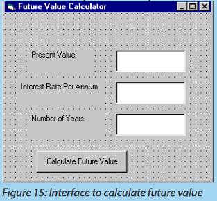
The functions that we create in a program are known as user defined functions. In this guide, we will learn how to create user defined functions and how to use them in C Programming
Functions are used because of following reasons:
a. To improve the readability of code.
b. Improves the re usability of the code, same function can be used in any program rather than writing the same code from scratch.
c. Debugging of the code would be easier if you use functions, as errors are easy to be traced.
d. Reduces the size of the code, duplicate set of statements are replaced by function calls.
a. Function prototype
A function prototype is simply the declaration of a function that specifies function’s name, parameters and return type. It doesn’t contain function body. A function prototype gives information to the compiler that the function may later be used in the program.
Syntax of function prototype in VB
Function FunctionName(arg1 As type1, arg2 As type2, ...) As return data types
In the above example public, Function FunctionName(argument1 As type1, argument As type2,...) As return data types
The function prototype provides the following information to the compiler:
1. name of the function is FunctionName
2. return type of the function is Double
3. two arguments of type (argument1 As type1, argument As type2) have passed to the function
The function prototype is not needed if the user-defined function is defined before the module program. Public indicates that the function is applicable to the whole project and Private indicates that the function is only applicable to a certain module or procedure.
Example a
Public Function FV (PV As Double, i As Double, n As Double) As Double
c. Function definition
A function definition specifies the name of the function, the types and number of parameters it expects to receive, and its return type. A function definition also includes a function body with the declarations of its local variables, and the statements that determine what the function does.
Example b
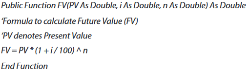
In this example, a user can calculate the future value of a certain amount of money he/she has today based on the interest rate and the number of years from now, supposing he/she will invest this amount of money somewhere. The calculation is based on the compound interest rate.
d.Function calling
When you call a function you are basically just telling the compiler to execute that function. To call a function “Call” key word can be used or not.
Syntax
[procedureName][argumentList]
Example c
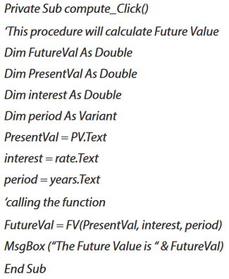
The following program will automatically compute examination grades based on the marks that a student obtained. The code is shown below:
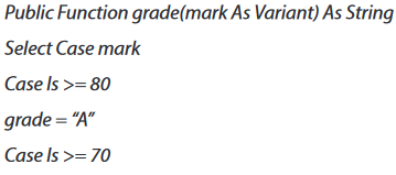
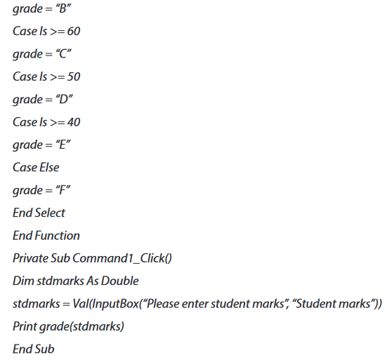
e. Passing Arguments by Value and by Reference in Visual Basic
In Visual Basic, you can pass an argument to a procedure by value or by reference. This is known as the passing mechanism, and it determines whether the procedure can modify the programming element underlying the argument in the calling code.
The procedure declaration determines the passing mechanism for each parameter by specifying the ByVal or ByRef keyword.
e. 1. Passing Arguments by Value
You pass an argument by value by specifying the ByVal keyword for the corresponding parameter in the procedure definition. When you use this passing mechanism, Visual Basic copies the value of the underlying programming element into a local variable in the procedure. The procedure code does not have any access to the underlying element in the calling code.
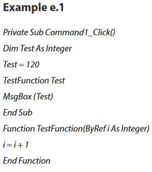
After executing the above codes output will be: 1
e. 2. Passing Arguments by Reference
You pass an argument by reference by specifying the ByRef keyword for the corresponding parameter in the procedure definition. When you use this passing mechanism, Visual Basic gives the procedure a direct reference to the underlying programming element in the calling code.
Example d.2
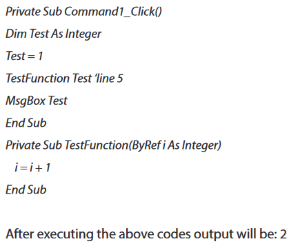
e. 3. Differences between Passing an Argument By Value and By Reference
When you pass one or more arguments to a procedure, each argument corresponds to an underlying programming element in the calling code. You can pass either the value of this underlying element, or a reference to it. This is known as the passing mechanism.
Application activities 5.5.
1. Write a VB function to find the Maximum of three numbers
2. Write a VB function to sum all the numbers in a list
Sample List : (8, 2, 3, 0, 7)
Expected Output : 20
5.2.3 Procedures
Learning activities 5.6.
1. Write a function which allows a user to input monthly salary and then allow him/her to withdraw amount which does not exceed 90% of his/her monthly income otherwise the software should inform the user that the remaining amount (10%) is reserved for the future needs saving .
A procedure is a block of Visual Basic statements inside Sub, End Sub statements. Procedures do not return values. A procedure, in any language, is a self-contained piece of code which carries out a well-defined piece of processing.
a. Syntax of a procedure
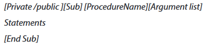
b.Types of procedure
b.1. Event procedures
Visual Basic has two kinds of procedures, event procedures and general procedures.
An event procedure is “attached” to an object and is executed when the relevant event impinges on that object.
e.g., “Click” is an event procedure attached to a button, and is executed when the button is clicked (by the user, with the mouse). Event procedures are named by VB. VB creates a name for an event procedure by concatenating the name of the object and the name of the event, and putting an underscore between them.
e.g., the click event procedure for a button named “CmdQuit” will be named “CmdQuit_Click”.
b.2. General procedures
A general procedure is not attached to an object such as a button or a text field. A general procedure is located in the “general” section of a Form.
Unlike event procedures, general procedures are only executed when you explicitly call them from your code. You are responsible for naming general procedures, and you can give them any name you like (within normal VB naming rules).
e.g. suppose there are 10 different places in your program where you might want to issue the following error message (with a beep to attract the user’s attention):

Note: We use procedures and functions to create modular programs. Visual Basic statements are grouped in a block enclosed by Sub, Function and matching End statements. The difference between the two is that functions return values, procedures do not.
A procedure and function is a piece of code in a larger program. They perform a specific task. The advantages of using procedures and functions are:
•Reducing duplication of code
•Decomposing complex problems into simpler pieces•Improving clarity of the code
•Reuse of code
•Information hiding
Application activities 5.6.
1. Write a VB program using procedure which helps a business Woman who has a shop in Nyanza city southern province to input manufactured , expiring and buying year for each product that she has in the shop and then informs whether the product has expired or still valid.
END UNIT ASSESSMENT
1. What do you understand by an array?
2. Discuss about the use of arrays in program.
3. Give the syntax and steps to write a function and a procedure
4. Differentiate a function from a procedure
5. Differentiate a built in function from a user defined function and explain the use of each one
6. Write a VB procedure which solves quadratic equation (ax2+bx+c=0) each output must be underlined using a procedure called underline ().
7. Design a VB function program to find Factorial of an entered number
UNIT 6 : VISUAL BASICPROJECT
Key Unit Competency
To be able to connect Visual Basic Interface to Database and create a simple Visual
Basic standard desktop applications for a real life situation.
Introductory activity
GS Gisakura is a Twelve- Years- Basic- Education School that has a big number of students. The school is facing the problem of students’ information management and is
looking for an application to manage its students’ registration.
After elucidating the requirement specifications of the GS Gisakura's students’ registration system do the following:
1. Using Visual basic, create a front end interface for the GS Gisakura
students’ registration system.
2. Using MS access, create the database for the GS Gisakura’s students
registration system.
3. Using Open Database Connectivity (ODBC), link the front and back end
interfaces for the GS Gisakura students’ registration system.
4. Using Data Access Objects (DAO), Data controls and properties;
manipulate data of the GS Gisakura students’ registration system.
5. Design the front end interface basing on ergonomics rules
6.1. PROJECT 1: REQUIREMENT ANALYSIS AND PROJECT
PLANNING
In every software project, you need to collect and analyze the information about
what you are going to do. This phase in Software Development Life Cycle (SDLC) is
called requirement’ analysis.
To develop a Visual Basic Project, all requirements specifications must be gathered
so that the planning of the project can be realized.
6.1.1. VB Project Planning
The project planning is an important phase of a software development. It works
on the breakdown of activities, the scheduling, the human force distribution, its
recruitment and capacity development. The cost of the project is also done by
considering the size of work and manpower needed for its realization.
As each project should have its objectives, for example, the student registration
system should manage student registration information where every student
information in the system has to be recorded, stored and should be modifiable (edit,
add new, delete and update) by the authorized users.
6.1.2. Software requirement analysis
The software requirement or specification requirement phase allows both the
developers and their clients to have a common understanding of the project and
avoids mistakes that should cause failures. The requirements can be functional and
nonfunctional. Functional requirements are those requirements concerning actions
to be performed by the new system while nonfunctional requirements concern the
constraints, performance, safety, security, timing and the quality of the new system.
In case of the software that manages a school, the Software requirement should help
to understand the status of the school in terms of computerization, the intended
software and how it will work with the users in this phase. So, there is a need to
take sufficient time by conducting extensive interviews with all the people who are
going to use the software. In this case, the school administrators, teachers, students
and the school secretary have to give their views.
After, it is better to structure all collected data and analyze them for the development
of the program. All technical limitations that may arise on the client’s side must be
considered before the development of a list of specifications that meet the user’s
needs.
The template to be followed for the software functional requirements is described
hereafter. The main template is follows the points in the tablebelow.

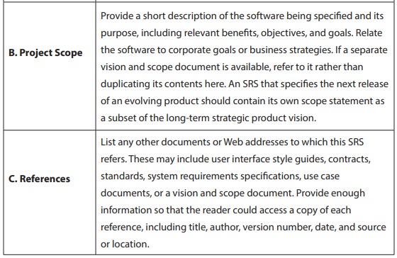
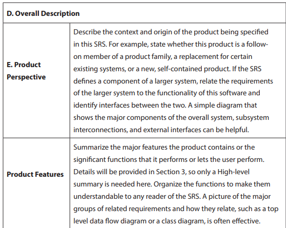
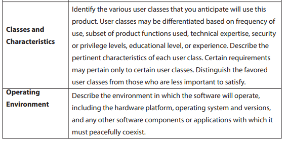
3. System Features
This template illustrates how to organize the functional requirements for the product
by system features and the major services provided by the product. This section can
be organized bymode of operation, user class, object class, functional hierarchy, or
combinations of these, whatever makes the most logical sense for your product.
4. External Interface Requirements
a. User Interfaces
Describe the logical characteristics of each interface between the software product
and the users. This may include sample screen images, any GUI standards or product
family style guides that are to be followed, screen layout constraints, standard buttons
and functions (e.g., help) that will appear on every screen, keyboard shortcuts, error
message display standards, and so on. Define the software components for which a
user interface is needed. Details of the user interface design should be documented
in a separate user interface specification.
b. Hardware Interfaces
Describe the logical and physical characteristics of each interface between the
software product and the hardware components of the system. This may include
the supported device types, the nature of the data and control interactions between
the software and the hardware, and communication protocols to be used.
c. Software Interfaces
Describe the connections between this product and other specific software
components (name and version), including databases, operating systems, tools,
libraries, and integrated commercial components. Identify the data items or
messages coming into the system and going out and describe the purpose of each.
Describe the services needed and the nature of communications. Refer to documents
that describe detailed application programming interface protocols. Identify data
that will be shared across software components. If the data sharing mechanism
must be implemented in a specific way (for example, use of a global data area in a
multitasking operating system), specify this as an implementation constraint.
d. Communications Interfaces
Describe the requirements associated with any communications functions required
by this product, including e-mail, web browser, network server communications
protocols, electronic forms, and so on. Define any pertinent message formatting.
Identify any communication standards that will be used, such as FTP or HTTP.
Specify any communication security or encryption issues, data transfer rates, and
synchronization mechanisms.
5. Other Nonfunctional Requirements
a. Performance Requirements
If there are performance requirements for the product under various circumstances,
state them here and explain their rationale, to help the developers understand the
intent and make suitable design choices. Specify the timing relationships for real
time systems. Make such requirements as specific as possible. You may need to state
performance requirements for individual functional requirements or features.
b. Safety Requirements
Specify those requirements that are concerned with possible loss, damage, or harm
that could result from the use of the product. Define any safeguards or actions that
must be taken, as well as actions that must be prevented. Refer to any external
policies or regulations that state safety issues that affect the product’s design or use.
Define any safety certifications that must be satisfied.
c. Security Requirements
Specify any requirements regarding security or privacy issues surrounding use of the
product or protection of the data used or created by the product. Define any user
identity authentication requirements. Refer to any external policies or regulations
containing security issues that affect the product. Define any security or privacy
certifications that must be satisfied.
d. Software Quality Attributes
Specify any additional quality characteristics for the product that will be important
to either the customers or the developers. Some to consider are: adaptability,
availability, correctness, flexibility, interoperability, maintainability, portability,
reliability, reusability, robustness, testability, and usability. Write these to be specific,
quantitative, and verifiable when possible. At the least, clarify the relative preferences
for various attributes, such as ease of use over ease of learning.
e. Other Requirements
Define any other requirements not covered elsewhere in the SRS. This might include
database requirements, internationalization requirements, legal requirements,
reuse objectives for the project, and so on. Add any new sections that are pertinent
to the project
6.1.3 Project1
Based on the request of your school to have a student registration system and by
following the software requirement specifications template given above, develop
the Requirements Document.
6.2. PROJECT2: FRONT END USER INTERFACE IN VISUAL BASIC
6.2.1. Understanding front end
In visual basic, the term Front End refers to the user interface, where the user
interacts with the program through the use of the screen forms and reports. The
Front End graphical user interface use buttons, text field and different icons to make
easy navigation of the application software.
6.2.2. Design the forms constituting a front end interface
Front-end interface for the GS Gisakura students’ registration layout are given below
and you are going to design the same layout and your own basing on SRS you have
elucidated in your school as case study.


6.3. PROJECT 3: BACK END DATABASE
(In Ms-Access, MySQL or any suitable RDBMS)
Database systems are comprised of a Front End and Back End. The Back End has the
tables that store data, including the relationships between the tables, data queries
and other behind the scenes technology that accepts information from and displays
information to the user via the Front End.
For example, when you are requesting for a birth certificate through Irembo there is
a number of information you provide through different forms and that information
is kept in the Irembo database tables.
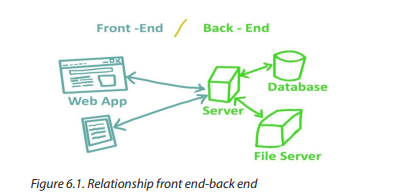
Back ends can be built using different Relational Database Management Systems
such as Microsoft Access, SQL Server, Oracle etc. User at the front end of a system
does not need to know how data is stored and how it is modified or retrieved.
Note: If you create a program that access a database:
• Programming language are used as Front End. Example: Visual Basic, HTML.
etc.
• Database management systems are used as Back End. Example: Microsoft
Access, My SQL, SQL Server, Oracle, etc.
Below is layout of created table in design view. Create a database and name it
“school” and create a table whose “student_reg” as a name, using your suitable
Database management system (in this book we have used MS access 2016) with
the same field names as below. After, you are going to design and create your own
database basing on SRS you found in your school as case study.
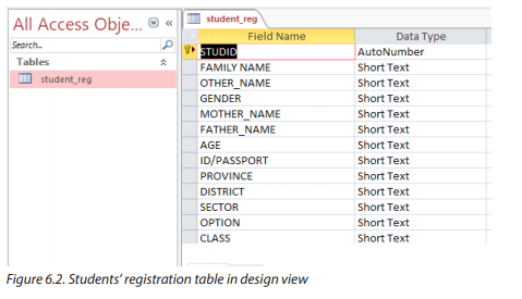
6.4. PROJECT 4: CONNECTING A VISUAL BASIC 6.0 PROJECT
TO A DATABASE (ODBC configuration)
A visual basic database application has three main parts: user interface, the database
engine and the data storage.
• The user interface: Is the Media through which the user interacts with
the application. It may be form or group of forms, a window or an ActiveX
document form.
• The database engine: Connects the application program with the physical
database files. This gives you modularity and independence from the
particular database you are accessing. For all types of database, the same
data access object and programming techniques can be used in visual basic.
• The data storage: Is the source of the data. It may be a database or a
text file. Database processing has become an integral part of all types of
complex applications. A database is a system that contains different objects,
which can be used together to store data. Using visual basic, you can create
applications easily and make them have efficient access to data.
6.4.1. ODBC (Object Database Connectivity) configuration
a. ODBC overview
ODBC strands for Open Database Connectivity, a standard database access method
developed by the SQL Access group in 1992. The goal of ODBC is to make it possible
to access any data from any application, regardless of which database management
system (DBMS) is handling the data. ODBC manages this by inserting a middle
layer, called a database driver, between application and DBMS. The purpose of this
layer is to translate the application’s data queries into commands that the DBMS
understands. For this to work, both application and DBMS must be ODBC compliant.
b. Create an ODBC connection for the Database
Step 1. Click Start button, and select Control Panel. Once the control panel gets
opened, click on Administrative Tools or tape it in search control panel if you do not
locate the Administrative Tools or just tape ODBC in start button search and click
ODBC data sources(32bit)
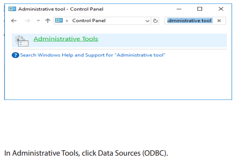
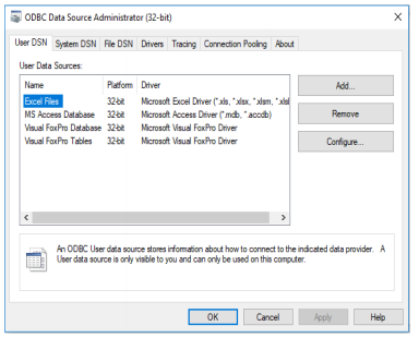

Step 2. Now we are going to add new database, click Add button and new window
will appear “Create New Data Source”, select the Driver do Microsoft Access (*.mdb)
for MS Access, click Finish Button.
Step 3: We’re almost done, let’s configure the ODBC for MS Access, under Data
Source Name, type the MyDatabase, please leave blank the description it’s optional.
Now, let’s select the path of your database .mdb once you found it select OK button.
The image shown below means that the Database .mdb is successfully located. Click
OK button to Finish the configuration. (MS Access Database Configuration done).
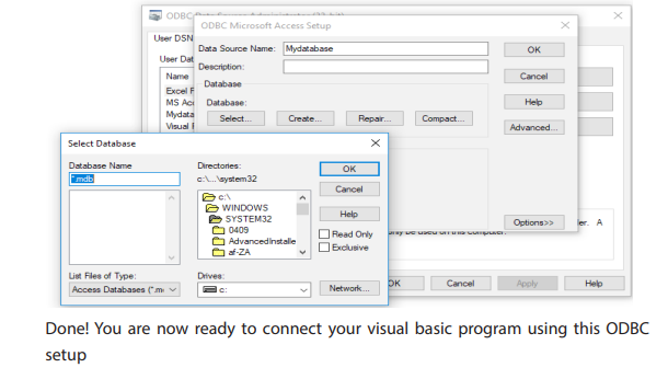
6.5. PROJECT 5: DAO, RDO AND ADO OBJECTS IN VISUAL
BASIC
Using all steps and guidance below, create connectivity between your backend and
frontend
a. Introduction
You may build VB database applications using data control, however, data control is
not a very flexible tool as it could only work with limited kinds of data and must work
strictly in the Visual Basic environment. To overcome these limitations, we can use a
much more powerful data control in Visual Basic, known as ADO control.
Data control is a control that allows connecting a VB program to a text database such
as (Sql Server, MS Access, MySQL, Dbase, FoxPro…). That control allows moving in
data base records, display, and manipulating data in a list of the available data base
records. It is adjusted on the form of other objects and you can define its properties.
There are many types of data controls; in Visual Basic, there are three data access
interfaces:Dao (Data Access Object), RDO (Remote Data Object), Ado (ActiveX Data
Object). Thelatest among the three is ADO, which features a simpler yet more flexible
object model than either RDO or DAO.
1. Data access object (DAO) is an object that provides an
abstract interface to some type of database or other persistence
mechanism. By mapping application calls to the persistence layer, DAOs
provide some specific data operations without exposing details of the
database. This isolation supports the Single responsibility principle. It
separates what data accesses the application needs, in terms of domainspecific objects and data types (the public interface of the DAO), from how
these needs can be satisfied with a specific , database schema, etc. (the
implementation of the DAO).
2. Remote Data Objects (abbreviated RDO) is the name of an
obsolete data access application programming interface primarily used
in Microsoft Visual Basic applications on Windows 95 and later operating
systems. This includes database connection, queries, stored procedures,
result manipulation, and change commits. It allowed developers
to create interfaces that can directly interact with Open Database
Connectivity (ODBC) data sources on remote machines, without having
to deal with the comparatively complex ODBC API (Open Database
Connectivity- Application Programming Interface). Remote Data Objects
was included with versions 4, 5, and 6 of Visual Basic; the final version of
RDO is version 2.0.
3. ActiveX data Object (ADO)
This control helps us to access a database data offering the possibility of
working on different data sources such as text files, relational data base etc.
i.Add ADO control
ADO controls contain multitudes of objects having properties, methods and events.
Access-connection: It allows your program to access a data source using a connection.
Its environment deals with transferring data.
ii. Recordset:
this property work with the records which can be accessed by an ADO control. Most
of methods are associated to this property. You can use this property to count the
number of records.
For example using the command: CmdRecordCount()
Private Sub CmdRecordCount_click()
Adodc1.Recordset.Movelast
MsgBox Adodc1.RecordSet.RecordCount ‘to count the number of records
End Sub
• Field: correspond to the fields of a database which are connected to the
program.
• Error: Errors may occur when a program fails to connect t, execute a
command or perform a given operation.
• Event: ADO uses the concept of events as other VB interfaces do, you can
use also event procedures.
• Recordsource: Recordsource property specifies the source of the records
accessible through bound controls on your form. If you set the recordsource
property to the name of an existing table in the database, all of the fields
in that table are visible to the bound controls attached to the Data control.
• Datasource: The datasource property specifies an object containing data
to be represented as a recordset object. It is used to create data-bound
controls with the data environment in visual basics.
Eg: a datasource can be a spreadsheet, text file.
To add the ADO control on the form perform the following steps:
1. Select the command Component in the project menu
2. Click on Controls in the dialog box which opens
3. Select Microsoft Ado Data Controls 6.0 (OLEDB)
4. Click ok button
5. This control will be added to the toolbox.
6. To connect ADO objects on the data source use a « ConnectionString »
and specify the datasource (the database name you want to connect)
7. Then you have to specify the access path after clicking the connection
property.
Let us go a bit details and do practice
Select components in Project Menu or use keyboard shortcuts CTRL+T In
components check in check boxes for:
• Microsoft ADO Data Control 6.0 (OLEDB) &Microsoft DataGrid Control 6.0
(OLEDB) By right click in tool box, we obtain also components
• Double click on the form and write the following codes:
Private Sub Form_Load()
Adodc1.ConnectionString = “”
Adodc1.RecordSource = “select * from student”
Set DataGrid1.DataSource = Adodc1
End Sub
• Create a connection string by making right click on adodc control which is
on the form, then select properties.
• On the properties page which opens, choose build and select the path
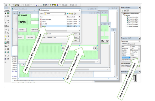
b. Method of the data control
Data control properties
• Name: you can keep data1 or put the one of your choice
• Caption=put your own message or leave it blank
• Connect=access
• Database name= browse and get the Employee database.
• Recordset type= table
• Record source=name of the table
• Visible= choose false so that when you run your application, the data
control will not appear
Data control has many methods like move first, move last, move next, and move
previous which are used to move through the records.
MoveFirst: will move the record pointer to the first record in the recordset.
MoveNext: will move the record pointer to the next record in the recordset
MovePrevious: will move the record pointer to the previous record in the recordset
MoveLast: will move the record pointer to the last record in the recordset
6.6. PROJECT 6 DATA CONTROLS, PROPERTIES AND DATA
MANIPULATION AND CODING
(adodc, recordset, addnew, delete, update, movenext, movelast, movefirst,
moveprevious code in vb for data manipulation)
To create an ADO Data Control that exposes a Recordset in your application, at the
minimum you need to do the following:
• Specify a Connection by filling in the ConnectionString property.
• Specify how to derive a Recordset by setting the RecordSource property
(which is a complex property requiring its own dialog box to set up).
The detailed steps are as follows:
6.6.1. Setting up ADO Data Control in Visual Basic 6.0
a. Adding ADODC (ADO Data Control) on toolbox
To add ADO Data control, make right click on toolbox dialog box and choose
component, then you will have a dialog box and tick Microsoft ADO Data Control
6.0(OLEDB) and click OK as shown below:
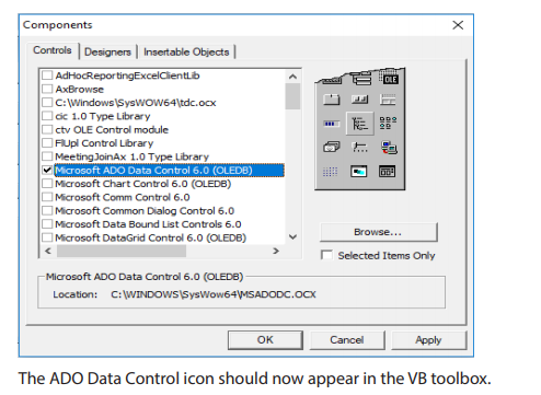

b. RECORDSET
Recordset property:
A recordset object provides a logical representation of a record in a table, or in the
results of a query. There are three types of recordset object:
1. Table: this type of recordset provides access to all of the record and field
in a specified table. The contents of records can be updated using the
table type, but only one table can be referenced by this type of recordset.
Data access is faster, since it has a direct reference to the table.
2. Dynaset: the dynaset type represents a selected (by SQL) set of records
from one or more tables. The records and fields contained in a dynaset
type are specified by a query. The data can be modified in the case of
dynaset type recordset.
3. Snapshot: the snapshot type recordset is similar to a dynaset but it is a
read only. The data cannot be updated. So you cannot use snapshot type
to modify records in a table. Snapshot type can be used if you want only to
view data or fill drop down from a table.
In a recordset, two special positions of record pointer are BOF and EOF.
• BOF is the beginning of the file before the first record
• EOF is the end of the record after the last record. The record pointer is to the
first record when BOF is reached and the last record when EOF is reached
Use of ADO control to connect database fields to different VB objects
Ho to connect database fields to textbox?
1. Select a textbox to connect
2. Press f4 key to display the property window.
3. In data source property, select the name of the connection control (here it
is Adodc1)
4. To display a given field, put the field name in « DataField »
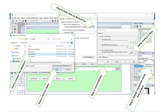
Use of methods
Add record into a database
b. To add a record into a database we use the method AddNew.
Syntax: Controlname.RecordSet.AddNew
Ex. Adodc1.RecordSet.AddNew
c. Delete a record
To delete a record we use delete method:
Private Sub CmdDelete_Click()
Adodc1.RecordSet.Delete
End Sub
To prevent the display of blank record, we move the record:
Private Sub CmdDelete_Click()
Adodc1.Recordset.Delete
Adodc1.Recordset.MoveNext’ prevent the error in case a record is not available
End sub
d. Refresh method
Refresh method is used to refresh database data; it allows to update the controls
according to the new values of the fields of a table.
Ex. Adodc1.Refresh
e. Update database fields
To modifying a database fields, you have to use the update method
Private Sub CmdUpdate_click()
Adodc1.UpDateRecord or
Adodc1.Update
End Sub
f.MoveNext method
Put the record pointer to the next record
Private Sub CmdNext_Click()
Adodc1.Recordset.MoveNext
End sub
g. MovePrevious method
Put the pointer on the previous method
Private Sub CmdPrevious_Click()
Adodc1.Recordset.MovePrevious
End Sub
h. MoveFirst method
Put the pointer on the first record of the database
Private sub CmdFirst_Click()
Adodc1.Recrdset.MoveFirst
End sub
i.MoveLast method
Put the pointer on the last record
Private Sub CmdLast_Click()
Adodc1.Recordset.MoveLast
End sub
Counting the records number
We use the method RecordCount:
Private Sub CmdCount_Click()
Adodc1.Recordset.MoveLast
MsgBox adodc1.Recordset.RecordCount
End sub
6.6.2. Building the interface and accessing the database • Interface is required to access a related database in order a user can add,
modify, retrieve data and so many other interactions.
• Drawing the interface, you have to set properties and then coding
• You have to add the data control to connect your database.
• Now let us add data control to be used to connect database with the
following steps below:
• Create a database in Microsoft access and an interface in visual basic6.0
then try to access it from VB form interface.
• Name your database created in Microsoft access for example name it
“school”
• Create three tables named for example Table1, Table2 and Table. Fill your
database in Table1 with the fields: RegNo, First name, Last name, Gender,
Mother’s name, Father’s name, ID/Passport, Province, District, Sector, Option
and class respectively.
• Using visual basic 6.0, draw the interface for your tables with the following
controls:
• 12 labels (RegNo, First name, Last name, Gender, Mother’s name, Father’s
name, ID/Passport, Province, District, Sector, Option and class)
• 12text boxes RegNo, First name, Last name, Gender, Mother’s name, Father’s
name, ID/Passport, Province, District, Sector, Option and class)
• Eight command buttons for Add, Delete, Next, Previous, Top, Bottom,
Update, and Exit.
Below is VB form that contains all above command buttons. Connect it with your
created database and access all information from school database and do the same for your own basing on created database through SRS. Below are codes that will guide you.
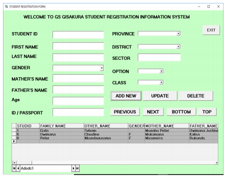
a. Set properties for the text box
• Data field=name of the field (for this example it is Table2)
• Setting properties for the combo box
• Data source=data control name (for the example above, data control name
is Adodc1)
• Data field=name of the field (depending on the name of field in you want
to be displayed in database)
1. Codes for combo box (Gender)
Double click the form and write the following codes:
Private Sub Form_Load ()
Combo1.AddItem “Male”
Combo1.AddItem “Female”
End Sub
Note: You may edit the name combo1.AddItem to “cmbgender” or other name you
want.
1. Codes for command buttons
• Command “Add”
Private Sub cmdadd_Click()
Data1.Recordset.AddNew
End Sub
Command “Update”
Private Sub cmdupdate_Click()
Data1.Recordset.Update
End Sub
• Command “Bottom”
Private Sub cmdbottom_Click()
Data1.Recordset.MoveLast
End Sub
• Command “Top”
Private Sub cmdtop_Click()
Data1.Recordset.MoveFirst
End Sub
• Command “Exit”
Private Sub cmdexit_Click()
Unload Form1
End Sub
Private Sub cmdexit_Click()
Unload me
End Sub
or
Private Sub cmdexit_Click()
end
End Su
• Command “Next” (using Data1)
Private Sub cmdnext_Click()
Data1.Recordset.MoveNext
If Data1.Recordset.EOF Then
Data1.Recordset.MovePrevious
End If End Sub
• Command “Next” (using Adodc1)
Private Sub Command2_Click()
Adodc1.Recordset.MoveNext
If Adodc1.Recordset.EOF Then
Adodc1.Recordset.MovePrevious
MsgBox “you are at the end”
End If
End Sub
• Command “Previous” (using Data1)
Private Sub cmdprevious_Click()
Data1.Recordset.MovePrevious
If Data1.Recordset.BOF Then
Data1.Recordset.MoveNext
End If End Sub
• Command “Previous” (using Adodc1)
Private Sub Command3_Click()
Adodc1.Recordset.MovePrevious
If Adodc1.Recordset.BOF Then
Adodc1.Recordset.MoveNext
MsgBox “you are at the end”
End If
End Sub
• Command “Delete”
Private Sub cmddelete_Click()
If MsgBox(“Are you sure?”, vbQuestion + vbYesNo,
“Deleting”) = vbYes Then
Data1.Recordset.Delete
Data1.Recordset.MoveNext
End If
End Sub
• Command “Find”
Private Sub cmdfind_Click()
find = InputBox(“Enter parent_id”)
.With Data1.Recordset
.Index = “primarykey” .Seek “=”, find
End With
End Sub
6.7. PROJECT 7: PRINCIPLES FOR DESIGNING A FRIENDLY AND
ERGONOMIC USER INTERFACE
Designing a good user interface is an iterative process. There are appropriate
techniques to use during the designing and implementation of a user interface. For
good looking and being attractive, the user interface should be SMART so that every
designed screen should support single action of real value to the users. This should
make it easier to learn, use, add, delete and other interactions for users.
a. Principles of a friendly user interface.
The following table is showing the main principles of a friendly user interface.
Each programmer should keep it as a bible to consult during the development of
applications in different Programming Languages.
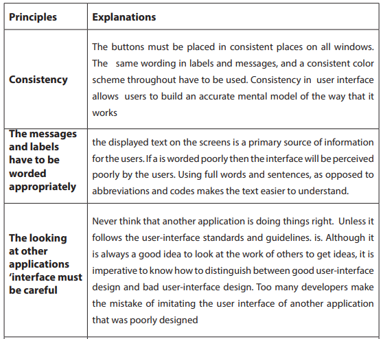
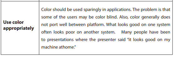
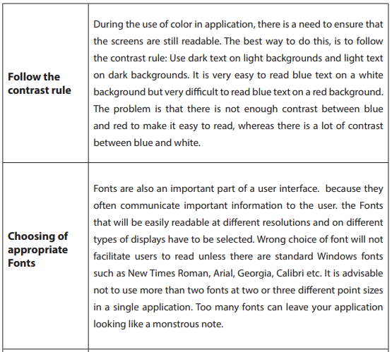
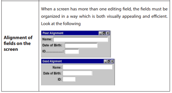

b. Principles for an ergonomic user interface
Ergonomics derives from two Greek words: ergon, meaning work, and nomoi, meaning natural
laws, to create a word that means the science of work and a person’s relationship to that work.
Ergonomics is a field of study that attempts to reduce strain, fatigue, and injuries by improving
product design and workspace arrangement. It makes things comfortable and efficient.
It is intended to maximize productivity by reducing operator fatigue and discomfort. Human
characteristics, such as height, weight, and proportions are considered, as well as information
about human hearing, sight, temperature preferences, and so on, in order to reduce or
eliminate factors that cause pain or discomfort
There are five aspects of ergonomics: safety, comfort, ease of use, productivity/performance,
and aesthetics. Based on these aspects of ergonomics, examples are given of how products
or systems could benefit from redesign based on ergonomic principles.
i. Safety: This has to do with the ability to use a device or work with a device
without short or long term damage to parts of the body.
ii. Comfort: Comfort in the human-machine interface is usually noticed first.
Physical comfort in how an item feels is pleasing to the user.
iii. Ease of use: This has to do with the ability to use a device with no stress
iv. Productivity/performance: Ergonomics addresses the performance of user
interface by providing more options to the users, enabling them to easily
and quickly skip some instructions as users’ choice.
v. Aesthetics: Signs in the workplace should be made consistent throughout
the workplace to not only be aesthetically pleasing, but also so that
information is easily accessible.
Project 6 activity
Improve your project by taking into consideration the principles of a friendly user
interface and an ergonomic user interface above.
UNIT 7: PROCESS MANAGEMENT ANDSCHEDULING ALGORITHM
Key Unit Competency:
To be able to explain how processes are managed by Operating System and to understand process scheduling algorithms
INTRODUCTORY ACTIVITY
Open MS EXCEL, type your school name and save the file as “my school”. Press a combination of CTLR +ALT+ Delete. Go to the Task Manager. Click on Processes Tab and answer the following questions:
a. What processes are running?
b. Describe what is displayed in the table.
c. Right Click on Microsoft EXCEL, Click on End Task. What do you observe? Is MS Excel still open or not? Why?
7.1 PROCESS
Learning activity 7.1.
Read the following text and answer the questions below. There are two categories of programs. Application programs (usually called just "applications") are programs that people use to get their work done. Computers exist because people want to run these programs. System programs keep the hardware and software running together smoothly. The most important system program is the operating system. The operating system is always present when a computer is running. It coordinates the operation of the other hardware and software components of the computer system. The operating system is responsible for starting up application programs, running them, and managing the resources that they need. When an application program is running, the operating system manages the details of the hardware for it. For example, when you type characters on the keyboard, the operating system determines which application program they are intended for and does the work of getting them there.
a. How do you call a program which is running in your computer?
b. Through the interface obtained after combining CTRL+ALT+DELETE, which programs are running? What are their differences?
c. Write down which ones are consuming a lot of memory space.
7.1.1. Definition
A process is a program in execution. It is an instance of program execution and it is not as same as program code but a lot more than it. A process is an ‘active’ entity as opposed to program which is considered to be a ‘passive’ entity. Attributes held by process include hardware state, memory, CPU etc.The 4 sections in which the process is divided are:
• Text: This is the set of instructions, the compiled program code, read in from non-volatile storage, to be executed by the process.
• Data: this is the data used by the process when executing. It is made up the global and static variables, allocated and initialized prior to executing the main.
• Heap of resources: These are physical or virtual components of limited availability within a computer system that are needed by the process for its execution. They include CPU time, memory (random access memory as well as virtual memory), secondary storage like hard disks and external devices connected to the computer system. The heap is managed via calls to new, delete, malloc, free, etc.
• Stack: It is used for local variables. Space on the stack is reserved for local variables when they are declared.

7.1.2. Process execution requirement
A process in execution needs resources like the Central Processing Unit (CPU), memory and Input/output devices. In current computers, several processes share Resources where one processor is shared among many processes. The CPU and the input/output devices are considered as active resources of the system as they provide input and output services during a finite amount of time interval while the memory is considered as passive resource.
A process is executed by a processor through a set of instructions stored in memory. This instruction processing consists of two stages: The processor reads (fetches) instructions from the memory one after another and executes each instruction. Process execution consists of a number of repeated steps of fetching the process instruction and the instruction execution. The execution of a single instruction is called an instruction cycle. Graphically, it is shown by the figure below:

7.1.3. Process vs. program
The major difference between a program and a process is that a program is a set of instructions to perform a designated task whereas the process is a program in execution. A process is an active entity because it involves some hardware state, memory, CPU etc. during its execution while a program is a passive entity because it resides in memory only. The differences between a program and a process are summarized in the table below:
 7.1.4. Process states
 When a process executes, it changes the states whereas a process state is defined as the current activity of the process. A process can be in one of the following five states.
a. New: This is the initial state when a process is first created but it has not yet been added to the pool of executable processes.
b. Ready: At this state, the process is ready for execution and is waiting to be allocated to the processor. All ready processes are kept in a queue and they keep waiting for CPU time to be allocated by the Operating System in order to run. A program called scheduler picks up one ready process for execution.
c. Running: At this state, the process is now executing. The instructions within a process are executed. A running process possesses all the resources needed for its execution i.e. CPU time, memory (random access memory as well as virtual memory), secondary storage like hard disks and external devices connected to the computer system. As long as these resources are not available a process cannot go in the running state.
d. Waiting: a process is waiting for some event to occur before it can continue execution. The event may be a user input or waiting for a file to become available.
e. Terminated: This is when a process finishes its execution. A process terminates when it finishes executing its last statement. When a process terminates, it releases all the resources it had and they become available for other processes.

Figure 7.3: process states diagram
7.1.5. Process control block (PCB)
A Process Control Block is a data structure maintained by the Operating System for every process. It is also called Task Control Block and it is storage for information about processes.
When a process is created, the Operating System creates a corresponding PCB and when the process terminates, its PCB is released to the pool of free memory locations from which new PCBs are made. A process can compete for resources only when an active PCB is associated with it.


APPLICATION ACTIVITY 7.1.
1. Do the following question
a. Describe what a process is? How does it differ from a program?
b. Describe in brief the structure of a Process Control Block.
c. Draw a labeled diagram for the process state transitions and explain the different process states.
d. What are the top 5 programs that are frequently used at your school?
2. Answer the following questions by true or false:
a. A process in the running state is currently being executed by the CPU.
b. The process control block (PCB) is a data structure that stores all information about a process.
c. CPU scheduling determines which programs are in memory.
7.2. THREAD Learning
Activity 7.2.
Visit the internet and make research and answer the following questions:
a. What is a thread? How does it differ from a process?
b. Explain the 2 types of threads
7.2.1. Definition of a Thread
A thread is the smallest unit of processing that can be performed in an Operating System. A thread is also called a lightweight process. Threads provide a way to improve application performance through parallelism.
In traditional operating systems, each process has an address space and a single thread of control. However, there are situations in which it is desirable to have multiple threads of control that share a single address space, but run in quasiparallel, as though they were in fact separate processes.
Each thread belongs to exactly one process and no thread can exist outside a process. Threads provide a suitable foundation for parallel execution of applications on shared memory multiprocessors.
Multiple threads can be executed in parallel on many computer systems. This multithreading generally occurs by time slicing, wherein a single processor switches between different threads. For instance, there are some PCs that contain one processor core but you can run multiple programs at once, such as typing in a document editor while listening to music in an audio playback program; though the user experiences these things as simultaneous, in truth, the processor quickly switches back and forth between these separate processes.

7.2.2 Difference between thread and process
A thread has some similarities to a process. Threads also have a life cycle, share the processor and execute sequentially within a process.

7.2.3 Types of threads
There are 2 types of threads namely User- level threads and Kernel level threads.
A. User - level threads
This type of thread is loaded in the user space only. The User space refers to all of the code in an operating system that lives outside of the kernel. The kernel does not know anything about them. When threads are managed in the user space, each process must have its own thread table. The thread table consists of the information on the program counter and registers. This is shown in the figure 7.5abelow:
Advantages of user - level threads:
a. Each process can have its own process scheduling algorithm. This will be discussed later in the unit.
b. User level threads can run on any Operating System.
c. Faster switching among threads is possible.
Disadvantages of User-level threads
a. When a user level thread executes a system call, not only that thread is blocked but also all the threads within the process are blocked. This is possible because the Operating System is unaware of the presence of threads and only knows about the existence of a process that constitutes these threads. A system call is a way for user programs to request some service from Operating System.
b. Multithreaded application using user-level threads cannot take advantage of multiprocessing since the OS is unaware of the presence of threads and it schedules one process at a time.
B. Kernel-Level Threads
These are threads that are managed by the Operating System. There is no thread table in each process as the case of user level threads. The kernel only has the thread table. The thread table keeps track of all the threads in the system. The kernel’s thread table holds each thread’s registers and state. The information at the kernel level threads is the same as that at the user - level threads but the difference is that the information at the kernel - level is stored in the kernel space and at the user level thread; information is stored in the user space. Kernel space is part of the OS where the kernel executes and provides its services. This is shown in figure 7.5b below.
Advantages of Kernel level threads
a. The OS is aware of the presence of threads in the processes. If one thread of a process gets blocked, the OS chooses the next one to run either from the same process or from a different one. A thread is blocked if it is waiting for an event, such as the completion of an I/O operation.
b. It supports multiprocessing. The kernel can simultaneously schedule multiple threads from the same process on multiple processors
Disadvantages of Kernel level threads:
a. The kernel-level threads are slow and inefficient. For instance, threads operations are hundreds of times slower than that of user-level threads.
b. Since kernel must manage and schedule threads as well as processes. Switching between them is time consuming.

Difference between User-Level and Kernel-Level Threads
Considering the above explanations of the 2 types of threats, the following table summarizes the differences between them.

7.2.4 Advantages and disadvantages of threads
The advantages and disadvantages of threads are presented in the table below:

Application Activity 7.2.
Answer the following questions:
1. What are benefits of threads?
2. Discuss the advantages and the disadvantages of
a. User level thread
b. Kernel level thread
7.3. PROCESS SCHEDULING
Learning Activity 7.3.
During his working session on his computer in the School laboratory, the Laboratory Technician was doing many activities at the same time. By working with his text in Microsoft Word, he was also charting with his friends on WhatsApp and also listening to his preferred Hip hop songs.
i. What allowed him to do three activities at the same time on only one computer?
7.3.1 Definition of process scheduling
Process scheduling refers to the order in which the resources are allocated to different processes to be executed. Process scheduling is done by the process manager by removing running processes from the CPU and selects another process on the basis of a particular strategy.
7.3.2 Scheduling Queue
The scheduling queue is a queue that keeps all the processes in the Operating System. The Operating System maintains a separate queue for each of the process states and PCBs of all processes in the same execution state are placed in the same queue. When the state of a process is changed, its PCB is unlinked from its current queue and moved to its new state queue.
The Operating System maintains the following process scheduling queues:
• Job queue: this queue keeps all the processes in the system.
• Ready queue: this queue keeps a set of all processes residing in main memory, ready and waiting to be executed. A new process is always put in this queue.
• Device queues: the processes which are blocked due to unavailability of an I/O device constitute this queue.
The scheduling queues are shown in the figure below:

All the processes entering into the system are put in a queue, called the job queue. The processes in the main memory that are ready and waiting for their chance to get executed are put in the queue called the ready queue.
It is common that a process undergoing execution may be interrupted temporarily, waiting for some other job to occur like completion of an I/O operation. All such waiting processes are put in a queue called a device queue.
A new process enters the ready queue and waits for its execution at the time it is allocated to a CPU.
7.3.4. Process State Model
A process can be in two main states namely running and not running. It is also called “the two process state model”. “The two process state model “is the model where two main states of the process i.e. running and not running are considered.

Suppose a new process P1 is created, then P1 is in Not Running state. When the CPU becomes free, the Dispatcher gives control of the CPU to P1 that is in Not Running state and waiting in a queue.
The Dispatcher is a program that gives control of the CPU to the process selected by the CPU scheduler
When the dispatcher allows P1 to execute on the CPU, then P1 starts its execution. Therefore P1 is in running state. If a process P2 with high priority wants to execute on CPU, then P1 should be paused or P1 will be in the waiting state and P2 will be in the running state. When P2 terminates, then P1 again allows the dispatcher to execute it on the CPU.
However there can be abnormalities in the running of processes whereby they block one another. This situation is called deadlock.
7.3.4.1. Deadlock
A deadlock is a situation where a process or a set of processes are blocked, waiting for some resource that is held by some other waiting processes. Here a group of processes are permanently blocked as a result of each process having acquired a subset of the resources needed for its completion and waiting for the release of the remaining resource held by other processes in the same group. This makes it impossible for any of the processes to proceed.

Coffman (1971) identified four (4) conditions that must hold simultaneously for a deadlock to occur:
a. Mutual Exclusion: a resource can be used by only one process at a time. If another process requests for that resource then the requesting process must be delayed until the resource becomes released.
b. Hold-and-Wait: in this condition a process is holding a resource already allocated to it while waiting for an additional resource that is currently being held by other processes.
c. No preemption: resources granted to a process can be released back to the system after the process has completed its task.
d. Circular wait: the processes in the system form a circular list or chain where each process in the list is waiting for a resource held by the next process in the list. This is shown in the figure below:

7.3.5. Schedulers
A scheduler is an operating system program that selects the next job to be admitted for execution.
Schedulers are of three types namely: Long-Term Scheduler, Short-Term Scheduler and Medium-Term Scheduler.
a. Long-Term Scheduler
It is responsible for selecting the processes from secondary storage device like a disk and loads them into main memory for execution. It is also called a job scheduler. The reason why it is called a long term scheduler is because it executes less frequently as it takes a lot of time for the creation of new processes in the system.
b. Short-Term Scheduler
This scheduler allocates processes from the ready queue to the CPU for immediate processing. It is also called as CPU scheduler. Its main objective is to maximize CPU utilization. Short-term schedulers, also known as dispatchers. The dispatcher is the module that gives control of the CPU to the process selected by the short-term scheduler. Short-term schedulers are faster than long-term schedulers. They execute at least once every 10 millisecond.
c. Medium Term Scheduler
Medium-term scheduler removes the processes from the memory (swapping). A running process may become suspended if it makes an I/O request therefore it cannot make any progress towards completion. In order to remove the process from memory and make space for other processes, the suspended process is moved to the secondary storage. This process is called swapping, and the process is said to be swapped out or rolled out. The medium-term scheduler is in charge of handling the swapped out processes.

The Comparison of the three different types of schedulers is summarized in the following table.

Application Activity 7.3.
Choose the suitable word(s) in bold to fill the following blanks:
a. An instance of a program execution is called ___________( Process, Instruction, Procedure, Function)
b. A scheduler which selects processes from secondary storage device is called______________( Short term scheduler, Long term scheduler, Medium term scheduler, Process scheduler).
c. The ____________ is used as the repository for any information of the process. (Process state, deadlock, CPU, PCB).
d. ____________is the module that gives control of the CPU to the process selected by the short term scheduler. (Dispatcher, processor, aging).
e. _____________ Scheduler select the process that is in the ready queue to execute and allocate the CPU to it. (Short term scheduler, Long term scheduler, Medium term scheduler, dispatcher).
7.3.4. PROCESS SCHEDULING ALGORITHMS
Learning Activity 7.4.
1. Open multiple applications Microsoft WORD, Microsoft EXCEL and one used Browser. Observe on the Task Manager which one is coming first in the applications list? Explain why?
2. On the Performance Tab, click on Resource Monitor and explain why the order of processes available is changing dynamically?
3. What does the computer base on to place a process at the top and other in middle?
Process scheduling algorithms are procedures used by the job scheduler to plan for the different processes to be assigned to the CPU.
Objectives of Process Scheduling Algorithms
• Maximization of CPU utilization by keeping the CPU as busy as possible.
• Fair allocation of CPU to the processes.
• To maximize the number of processes that complete their execution per time unit. This is called throughput.
• To minimize the time taken by a process to finish its execution.
• To minimize the time a process waits in ready queue.
• To minimize the time it takes from when a request is submitted until the first response is produced.
There are 5 scheduling algorithms used by the process scheduler and they include the following:
• First-Come, First-Served (FCFS) Scheduling
• Shortest-Job-First (SJF) Scheduling
• Priority Scheduling
• Round Robin (RR) Scheduling
• Multiple-Level Queue Scheduling
The above mentioned algorithms are either non preemptive or preemptive. Nonpreemptive algorithms means that once a process enters the running state, it cannot be preempted until it completes its allocated time. The preemptive scheduling means that a scheduler may preempt a low priority running process anytime when a high priority process enters into a ready state.
7.4.1. First Come, First-Served (FCFS) Scheduling
The basic principle of this algorithm is to allocate processes to the CPU in their order of arrival. FCFS is a non-preemptive scheduling algorithm. This algorithm is managed with a First in First out (FIFO) queue. It is non-preemptive because the CPU has been allocated to a process that keeps it busy until it is released.
When a process enters the ready queue, its process control block (PCB) is linked onto the tail of the queue. When the CPU is done executing a process and is free, the job scheduler selects from the head of the queue. This results into poor utilization of resources in the computer since it cannot utilize resources in parallel. When a set of processes need to use a resource for a short time and one process holds resources for a long time, it blocks all other processes leading to poor utilization of resources.
Key Terms:
• CPU Burst time: this is the time required to complete process execution in the CPU.
• Arrival time: this is the time at which the process arrives in the ready queue.
• Gantt chart: A Gantt chart is a horizontal bar chart illustrating process schedule.
• Completion time: This is the time at which process completes its execution.
• Wait Time: This is the time a process waits in the ready queue.
• Waiting Time = Completion time - Burst Time
• Turnaround Time: this is the total time between submission of a process and its completion.
• Turn Around Time = Completion Time - Arrival Time
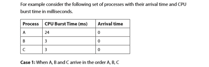
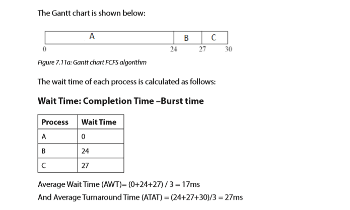
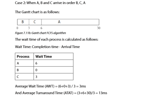
Case 2 is better than case 1 since AWT of case 2 is smaller than case 1. However the average waiting time under the FCFS algorithm is very long.
7.4.2 Shortest-Job-First (SJF) Scheduling
This is the algorithm that prioritizes the job whose execution time is smaller compared to other jobs already in the ready queue. When the CPU is free, it is assigned to the process of the ready queue which has the smallest CPU burst time. If two processes have the same CPU burst, the FCFS scheduling algorithm is used. SJF may either be preemptive or non preemptive.
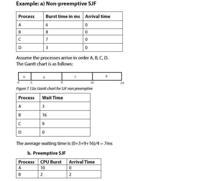

7.4.3. Priority Scheduling
In this algorithm, the CPU is allocated to the highest priority of the processes from the ready queue. Each process has a priority number. If two or more processes have the same priority, then FCFS algorithm is applied.
Priority scheduling can either be preemptive or non-preemptive. The choice is made whenever a new process enters the ready queue while some processes are running. If a newly arrived process has the higher priority than the current running process, the preemptive priority scheduling algorithm preempts the currently running process and allocates the CPU to the new process. On the other hand, the non-preemptive scheduling algorithm allows the currently running process to complete its execution and the new process has to wait for the CPU.

Assuming that the lower priority number means the higher priority, how will these processes be scheduled according to non-preemptive as well as preemptive priority scheduling algorithm? Compute the average waiting time and average turnaround time in both cases.
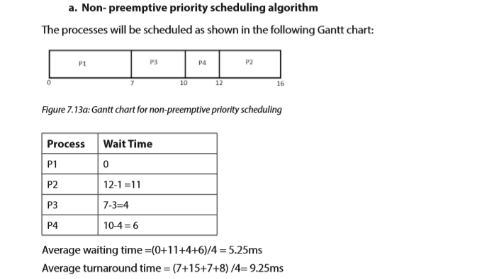


A priority scheduling algorithm can make some low priority processes wait indefinitely for the CPU causing the problem called starvation. Starvation problem is solved by the Aging Technique whereby the priority of the processes waiting for a long time in the ready queue is increased.
7.4.4. Round Robin (RR) Scheduling
Round Robin scheduling algorithm is a preemptive algorithm. To implement RR scheduling, ready queue is maintained as a FIFO (First In First Out) queue of the processes. New processes are added to the tail of the ready queue. The CPU scheduler picks the first process from the ready queue and sets a timer to interrupt after 1 time quantum and dispatches the process.
With the RR algorithm, the length of the time quantum is very important. If it is very short, then short processes will be executed very quickly. If it is too large, the response time of the processes is too much which may not be tolerated in interactive environment. Response time is amount of time it takes from when a request is submitted until the first response is produced.


7.4.5. Multiple-Level Queue Scheduling
In multilevel scheduling, all processes of the same priority are placed in a single queue.The figure 14 below shows the multilevel queue scheduling algorithm. It divides the ready queue into a number of separate queues. The processes are permanently assigned to one queue based on memory size, process priority and process type.

Each queue has its own scheduling algorithm. One queue may be scheduled by FCFS and another queue by RR method. Once the processes are assigned to the queue, they cannot move from one queue to another.
APPLICATION ACTIVITY 7.4.
Consider the following processes, with the CPU burst time given in milliseconds. The processes are arrived in P1, P2, P3, P4, P5 order of all at time 0.

c. Draw Gantt charts to show the execution using FCFS, SJF, non preemptive priority (small priority number implies higher priority) and RR (quantum =1) scheduling.
d. What is the waiting time of each process for each one of the above scheduling algorithms?
END OF UNIT ASSESSMENT
Answer the following multiple choice questions.
1. An OS program module that selects the next job to be admitted for execution is calleda. Schedulerb. Compilerc. Throughputd. None of the above2. A short term scheduler executes at least once everya. 1msb. 10msc. 5msd. None of the above3. A program responsible for assigning the CPU to the process that has been selected by the short term scheduler is known asa. Schedulerb. Dispatcherc. Debuggerd. None of the above4. The indefinite blocking of low priority processes by a high priority process is known asa. Starvationb. Deadlockc. Agingd. None of the above5. The technique of gradually increasing the priority of processes that wait in the system for a long time is calleda. Agingb. Throughputc. FCFSd. None of the above6. FIFO scheduling isa. Preemptiveb. Non preemptivec. Deadline schedulingd. None of the above7. A situation where a process or a set of processes is blocked, waiting for some resource that is held by some other waiting processes:a. Mutual exclusionb. Hold and waitc. Deadlockd. None of the aboveII. Answer the following structured questions:1. What do you understand by the following terms?a. Processb. Process statec. Process control block2. Draw a labeled diagram for the process state transitions.3. Explain the following:a. Short term schedulerb. Long term schedulerc. Medium term scheduler4. Compare the process and program.5. What is the role of PCB? List the attributes of PCB.6. What are benefits of threads?7. What are the differences between user level threads and kernel supported threads?8. For the following example, calculate the average waiting time and average turnaround time for the following algorithms.a. FCFSb. Preemptive SJFc. Round Robin (1 time unit)
 Draw the Gantt chart and calculate the waiting time and the average turnaround time for each of the following scheduling algorithms:a. FCFSb. Non preemptive SJFc. Preemptive SJF10. Differentiate preemptive and non preemptive scheduling giving the application of each of them.11. Suppose the following jobs arrive for processing at the times indicated. Each job will run the listed amount of time.
 a. Give the Gantt chart illustrating the execution of these jobs using the nonpreemptive FCFS and SJF scheduling algorithm.b. What is the wait time of each job for the above algorithm?12. For the following set of processes, find the average waiting time using Gantt chart fora. SJFb. Priority scheduling
UNIT 8: FILE MANAGEMENT
Key unit competency
To be able to describe role of operating system in file management and explain file management.
Introductory ActivitySwitch
on your computer, open a new document of Microsoft word and type the following text: “The price of success is hard work, dedication to the job at hand, and the determination that whether we win or lose, we have applied the best of ourselves to the task at hand.” Vince LombardiSave the text on the desktop, then answer the following questions:
1. Why is it important to save the document?
2. As you have saved the document on the hard disk, can you give the location (physical address) precisely where it is saved on the Hard Disk?
3. Discuss hat happen when you save 2 documents having the same name?
4. Give the difference between document, file and folder?
5. List and explain properties of the saved document?
6. Explain why application software has different icons while folders always have the same icon?
7. Discuss precautions to protect your document from deletion and editing by unauthorized persons?
8. What are the file system used by operating systems?
8.1. Understanding computer file
Learning Activity 8.1.
1. Observe carefully the figure below and respond to the asked question
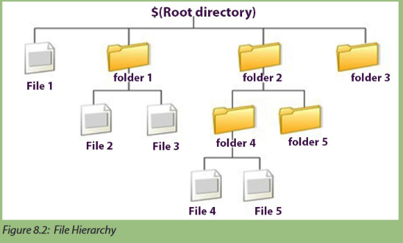
2. What do you think, the above figure represents?
3. Discuss the role of the root directory in the above figure.
4. Differentiate a file and folder in the above figure.
8.1.1 Definition of a computer file and folder
a) Definition of a computer file
A computer file is a collection of data or information that has a name, called the filename recorded on a memory storage device like hard drive, USB flash drives or portable SD card.
b) Definition of a folder
A folder is the virtual location for applications, documents, data or other sub-folders. It is a named collection of related files that can be retrieved, moved, and otherwise manipulated as one entity. So a folder is a special type of file on your computer’s file system which contains other files and folders.
c) Difference between File and Folder
•The basic difference between file and folder is that file stores data while folder stores files and other folders.
•The folders, often referred to as directories, are used to organize files on a computer. The folders themselves take up virtually no space on the hard drive.
•The files store data, while folders store files and other folders.
•The file is created by any application program while folder is created by the operating system. The folders are used to organize files on a computer.
•There are many types of files because there are thousands of application programs but folders don’t have types because there is only one operating system running the computer
•In case of Microsoft Windows, folders are opened through windows explorer and files are opened using a specific application program.
d) Properties of a File
The basic properties of a file are:
•Name: It is the only information which is in human readable form.
•Identifier: The file is identified by a unique tag (number) within file system.
•Type: It is needed for systems that support different types of files.
•Location: Pointer to file location on device.
•Size: The current size of the file.
•Protection: This controls and assigns the power of reading, writing, executing.
•Time, date, and user identification: This is the data for protection, security, and usage monitoring.
Note: In Microsoft Windows operating system, to view properties about a file or folder, right-click it and then select Properties. When a file or folder is selected, its properties can also be displayed by pressing Alt+ Enter.
8.1.2. File StructureA.
Definition
A file structure is defined according to the required format that the operating system can understand like:
•A file has a certain defined structure according to its type.
322Computer Science Senior 6 Student Book
•A text file is a sequence of characters organized into lines.
•A source file is a sequence of procedures and functions
.•An object file is a sequence of bytes organized into blocks that are understandable by the machine.
When an operating system defines different file structures, it also contains the code to support these file structure.
B. Classifications of file
There are two basic classification of the file: text file and binary file
.•Text files: the files that contain text. Each byte is an ANSII character or each 2 types is a Unicode character.
•Binary files: The bytes in a binary file do not necessarily contain characters. These files require a special interpretation.
C. File attributes
File attributes are settings associated with files that grant and deny certain rights to how a user and the operating system can access that file.
The following are file attributes for the windows operating system:
•Read-only attribute: it allows a file to be read only and nothing can be written to the file or changed
.•Archive attribute: it tells windows operating to back up the file.
•System attribute: system file
.•Hidden attribute: File will be hidden.
In Linux operating systems, there are three main file attributes: read (r), write (w), execute (x).
•Read: Designated as an “r”; it allows a file to be read, but nothing can be written to or changed in the file.
•Write: Designated as a “w”; it allows a file to be written to and changed.
•Execute: Designated as an “x”; it allows a file to be executed by users or the operating system.

D. File management operations
The operating system maintains a secure and well managed file system for all the users of the computer system. Mechanisms will have to exist to ensure correct and authorized use of any of the files under the file manager’s care. The file manager is the most visible to the user, as the user has specific file requirements and expects requirement results to be evidenced. The file manager aims to ensure data integrity and ensures that files are kept secure. In order to do this the file manager maintains accurate information about all the files, their use and their movement throughout any file management system. A file is created, modified or deleted in some way as a direct result of some form of processing activity - which in turn is undertaken by the process manager. As such the file manager needs to ensure that all its files are fully protected from misuse or accidental damage at all times.The File Manager (FM) has a predetermined policy that states how a file is created, used, stored and retrieved.
D. Typical responsibilities of a File Manager include:
•create and delete files•allocate and de-allocate file space - communicating availability to others
•track where files are stored - referring to files by symbolic name (the user does not have to worry about exact storage location)•store files efficiently
•identify and list all the files owned by a particular owner
•add or delete authorized users and their files•access files efficiently, e.g., to retrieve files just using their symbolic names
•share files
•control access to files, for example preventing a data file from being corrupted
•reallocate file space•protect files from the failure of the operating system (or hardware)
•be able to store files to new storage media, such as additional disks or drives
E. Directory structure
A directory is basically a set of linked files whereby they are organized in a way suited to the humans that they serve. The file manager will observe a set of rules (a policy) in which it will look after the directory and access rights to the files contained within. Directories are organized on a volume, (HDD, FDD, Tape, etc.). This organization provides a logical and controlled access to files. The normal organization is a tree structure. This provides easy and fast access and searches. Each directory entry will contain fields to indicate:
1. A symbolic name of the file
2. The size and the position of the file on the volume
3. The type of access permitted to the file
F. File Names
Files may be identified as follows:
-Absolute Name (complete name) Volume I Directory Path FileName.Ext
Example: (DOS) C:\public\help\test.hlp
•Relative Name: FileName.ext (short name) (Retrievable from current directory)
• Extension Indicates file type(contents & use of file)
8.1.3 File System
The File system is used to store and organize data on media, such on hard disk, USB flash disks or portable SD card.
The computers use particular kinds of file systems which depends on the operating system installed on the computer. Normally, the computers organize data in folders and folders contain files and other folders. The Microsoft Windows operating system have two types of file systems FAT (File Allocation Table) and NTFS (New Technology File System).
a) FAT File Systems
The FAT File System is simple, manageable and robust. It was created by Microsoft in 1977 and is widely used and found in different portable and embedded devices. Its organization is represented in the figure below.

Description:
The FAT file system originates from its prominent use of an index table that is allocated at the time of formatting. The index table is made up of clusters. A cluster is a unit of space which is used for storage of files and folders. Each cluster contains entries for storage in the disk. Each entry contains
•The total number of clusters in the file,
•An unused disk space,
•The special reserved areas of the disk.
The root directory of the disk contains the total number of cluster files in each file of that directory. The operating system then traverses the FAT table by looking through the cluster files of each disk file and then making a cluster chain till the end of the file is reached.
The FAT file system offers good performance in light-weight implementations. It makes the data sharing easy and convenient. It is also a useful format for solid state memory cards. Due to technology advancement and the increased need for more space, various versions of FAT file systems have evolved. Some of them are mentioned below:
•FAT 12: it was the first system introduced and had a storage capacity of 32 MB
•FAT16: it has a storage capacity of 2 GB
•FAT32: it is the third and latest file system and has a storage capacity of 8 GB
However, in FAT there is no security of data and it is not easily recoverable. This file system is also used to format the hard disk for ‘multi-booting’ the OS configuration.
b) NTFS file system
NTFS is a widely popular file system and it was introduced after the FAT file system. It was developed in 1993 and it was first used in the operating system MS Windows 3.1. Its mode of functioning is represented in the following figure.

Description:
It supports the data storage capacity up to 256 TB. It is used in all the latest versions of MS Windows such as MS Windows 10, MS Windows 8, MS Windows 7, MS Windows Vista, MS Windows XP, MS Windows 2000.
NTFS has an advanced data structure and sectors writing technique, improved security, and high capability of space utilization. NTFS has several improved features over FAT file system that are stated below:
•It is more stable and reliable
•It supports automatic recovery record the information in case of hard disk crash
•It has high speed to read and write data from the hard drive•It has high security over individual files and folders
•It supports multi-booting system
•The NTFS’s data can be shared and accessed over the network
•It has File Encryption
NTFS system is a better file system. It comes with high security and data safety whereas the FAT file system is low on data security and it can be easily modified and shared by anyone.
c) Comparison between NTFS and FAT File Systems
The File System is the most popular and widely used technique to store data on different types of storage memory devices such as a hard disk, memory card and USB Flash Disk. The data can also be upgraded or degraded while formatting the system. The devices write and store the data in their systems so that the data can be modified, accessed, deleted, or distributed at the time of need. Both NTFS and FAT are two different methods and they store the data in a structured way on a disk partition.

As there are various Operating Systems in the world, there are also numerous File Systems used and specific to each OS.
Linux File Systems are ext2, ext3 and ext4 while MAC OS file systems are APFS (Apple File System).
8.1.4. Hierarchical File System
A hierarchical file system shows how drives, folders and files are organized in the operating system. In a hierarchical file system, the drives, folders, and files are displayed in groups, which allows the users to see only files they are interested in.
The example below illustrates the hierarchical file system:

8.1.5. File manipulation functions
The File Manipulation functions allow the user to manipulate directories/folders by creating, opening, saving documents, etc. The following are some of the typical file operations:
1. Creating: It helps in creating a new file at the specified location in a computer system. The new file could be a word document, an image file or an excel worksheet.
2. Saving: It helps in saving the content written in a file at some specified location. The file can be saved by giving it a name of our choice.
3. Opening: It helps in viewing the contents of an existing file.
4. Modifying: It helps in changing the existing content or adding new to an existing file.
5. Closing: It helps in closing an already open file.
6. Renaming: It helps in changing the name of an existing file.
7. Deleting: It helps in removing a file from the memory of the computer system.


The application of the above functions will depend on the kind of operating system used. In this case Microsoft Windows is used.
8.1.5.1 Access files and folders using command prompt
Step1 1:Open Run command(Win key+R) and type cmd for command prompt then press enter key.
This will open the command prompt.
Step 2:Now write “Start file_name or start folder_name” in the command prompt ,
for example:- write “start mspaint” it will open ms-paint automatically.

Note: - These steps only allow you to access files, folder or software which is present in the “c” drive or system drive. To access file/folder from another driver you need to change drive in the command prompt, then you will access the files/folders from another drive. You can also hide files and folder using command prompt. To change one drive to another drive, type drive name followed by “:”. It will change default drive(c
to your required drive
8.1.5.1 File and folder viewing using windows explorer
•Hide/Show hidden files
In most of the operating systems, system files are hidden because an accidental deletion of one of them can make the whole system failing or crashing. Sometimes, the user can decide to see the hidden folders and files or not. To hide or unhide files and folders, do the following actions:
1. Open Folder options on your Windows PC
2. Navigate to “View” tab on Folder Option.
3. Scroll down the horizontal scroll bar on the “Advanced setting” of the view tab till you get the option “Hidden files and folder“.
4. You will get two check boxes under “Hidden Files and folder” as
•Don’t show hidden files, folder or drives
•Show hidden files, folder and drives
5. Just select “Don’t show hidden files, folder or drives” to hide the hidden files and folder and select “Show hidden files, folder and drives” to show those hidden files and folder.
6. Now “Apply” all the changes and click on “ O K “.That is it.
Assigning the hidden attributes to File/folder in Windows
To assign the hidden attribute to files or folders, do the following steps:
1. Select the file/folder that you want to make hidden.
2. Right click of mouse on that file and choose “Properties“.
3. Navigate to “General” tab. (By default that will on the general tab. If not then navigate to it)
4. On the “Attributes” section you will get a check box “Hidden“.
5. Just tick that “hidden” check box.
6. Now “Apply” all the changes and click on “OK“.
7. Now the selected file/folder is hidden.Remove the hidden attribute from a file/folder in Windows
The steps to remove the hidden attributes are:
a. First you need to show the hidden files or folder to view the hidden files/
b. folder by following the above process.
c. Select the file/folder whose hidden attribute you want to remove. (Note: Hidden files/folder are viewed as faded)
d. Right click of mouse on those files/folder and choose “Properties“
e. Navigate to “General” tab. (By default that will on the general tab. If not then navigate to it)
f. On the “Attributes” section you will get an check box “Hidden”. Just unchecked that “Hidden” check box. Now “Apply” all the changes and click on “OK“.Now the hidden attribute for the selected file/folder is removed and it is converted to general file/folder.
Application Activity 8.1.
Question A
1. What do understand by a cluster?
2. List and explain various version of FAT file system?
3. Investigate why it important to organize file and folders in hierarchal model?
4. What are the advantage of NTFS file system over the FAT file system?
5. What is the difference between home directory and working directory?
6. Distinguish the absolute path name and relative path name?
Question B
1. How to view and change the file attributes in Windows 10
2. Is it possible to create a folder using application software? Justify your answer?
3. Is it possible to create a file using an operating system? Justify your answer?
4. Differentiate the folder and directory?
8.2. FILE TYPE
Learning Activity 8.2.
Observe carefully the figure below and respond to the asked question

1. What did you find in the figure above?
2. Discus why the above files do not have the same graphical representation?
3. How does the operating system recognize the application software that open the file?
4. How can an operating system make use of the file types that it recognizes?
8.2.1. Understanding file type
File type refers to the ability of the operating system to distinguish different types of file such as text files, source files, binary files and others. Many operating systems support many types of files and modern operating system has the following types of files:
a) Ordinary Files or Regular
FileTherefore, all files created by a user are Ordinary Files and belong to any type of application program. Ordinary Files are used for storing the information about the user Programs
Example: Notepad, Paint, C Program, Songs, Database, Image
b) Directory files
There are files stored into the particular directory or folder.
Example: a folder named songs which contains many songs.
c) Special Files
The special files are files which are not created by the user and are files needed to run a System and are created by the Operating System. It means all the files of an operating system are referred as special files.
2.2. File Extension
a) Definition of a file extension
A file extension also called a file suffix, is the character or group of characters after the period that makes up an entire file name.
Example:
Senior6mpc.vlc(the file extenstion here is vlc)
The File extension helps the operating system to determine which program on computer the specific file is associated with and indicates the file type.
When a user attempts to open a file, the operating system checks the file extension and open the file using the associated application program. The Operating system uses file extensions to indicate the type of each file.
b) Type File and File Extension


c) File Extensions vs File Formats
File extensions and file formats are often used as interchangeably terms which is not true. In reality, however, the file extension is just 3 or 4 characters after the period in the file name while the file format indicates the way in which the data in the file are organized ; in other words it specifies what type of file it is.
Example: In the file name marks.xls, the file extension is xls which indicating that this is a spreadsheet file created in MS Excel.
Application Activity 8.2.

1. File type can be represented by
a. file name
b. file extension
c. file identifier
d. none of the mentioned
2. Name and describe the two basic classifications of files.
3. Name and describe the two basic classifications of files.
4. Distinguish between a file type and a file extension.
5. List advantages of operating system “knowing” and supporting many file types.
6. What would happen if you give the name "myFile.jpg" to a text file?
7. Complete the 3rd column of the table below with appropriate extensions of files.
8.3. FILE ACCESS MECHANISMS
Learning Activity 8.3.
Using DOS command, Create a folder structure for the small business company with three departments namely: Accounts, Personnel and Marketing.
The Accounts department wants to organize its files into Invoices Client folder and Expenses Client folder, the Personnel department wants organize its files in Wages Clientfolder, Contract Client folder and Disciplinary Client folder and the Marketing department wants organize its files in Client folder and Public Relations Client folder. Answer the following questions:
1. How do you access disciplinary folder in personal department?
2. Give the full path to access the public relation folder
The File access mechanism refers to the manner in which the records of a file may be accessed. When a file is used with the Central Processing Unit (CPU), then the stored information in the file must be accessed and read into the memory of a computer system.
Various mechanisms are provided to access a file from the operating system. There are 3 ways to access files: Sequential access, Direct Access and Index Access
8.3.1 Sequential Access method
It is the simplest access mechanism in which information stored in a file are accessed in an order such that one record is processed after the other.

A sequential access is that in which the records are accessed in some sequence. The information in the file is accessed in order where one record is accessed after another. This access method is the most primitive one.
Sequential access generally supports a few operations:
•Read Next: Read a record and advance the tape to the next position.
•Write Next: Write a record and advance the tape to the next position
.•rewind
•Skip n records: It may or may not be supported. N may be limited to positive numbers, or may be limited to +/- 1.

Example:
•Editors and compilers usually access files in this manner
.•Magnetic tape (cassette) operation.
8.3.2 Direct / Access method
It is an alternative method for accessing a file, which is based on the disk model of a file, since disk allows random access to any block or record of a file. In access method, file is viewed as a numbered sequence of blocks or records which are read or written in an arbitrary manner i.e. there is no restriction on the order of reading or writing.

Direct / Random access is the file access method that access the records directly. Each record has its own address on the file with by the help of which it can be directly accessed for reading or writing. The records need not be in any sequence within the file and they need not be in adjacent locations on the storage medium.Random access jump directly to any record and read that record.
Operations supported by direct / random access method include:
•Read n: read record number n.
•Write n: write record number n.
•Jump to record n: could be 0 or the end of file.
•Query current record: used to return back to this record later.

Comparison between Random and Sequential Data Access
Comparing random versus sequential operations is one way of assessing file efficiency in terms of disk use.
a. Sequential file access
•Accessing data sequentially and is much faster than randomly access because of the way in which the disk hardware works.
•Sequential file access allows data to be read from a file or written to a file from beginning to end.
•It is not possible to read data starting in the middle of the file,
•It is not possible to write data to the file starting in the middle using sequential methods.
b.Random Access Files,
•Random access files permit non sequential access to the files’ contents.
8.3.3. Indexed sequential access method
In this method an index is created which contains a key field and pointers to the various block. To find an entry in the file for a key value, we first search the index and then use the pointer to directly access a file and find the desired entry. With large files, the index file itself may become too large to be keep in memory. One solution is to create an index for the index file. The primary index file would contain pointers to secondary index files, which would point to the actual data items.
Indexed Sequential Access Method allows records to be accessed either sequentially (in the order they were entered) or randomly /directly (with an index). Each index defines a different ordering of the records.

Application Activity 8.3.
1. Explain the Indexed Sequential Access Method
2. Compare sequential and direct file access.
3. Explain why it is not possible to write data in the middle of the file using sequential methods?
4. What are advantage of sequential access?
5. File access is independent of any physical medium.
a. How does the Operating System implement sequential access on a disk?
b. How does the Operating System implement direct access on a magnetic tape?
8.4. FILE SPACE ALLOCATION
Learning Activity 8.4.
Observe the below picture and answer below question

1. What do you think of the above figure?
2. How does an operating system track the file stored in the secondary memory?
3. Discuss mechanism used by the OS to allocate files memory space on secondary memory?
8.4.1. File space allocation
File space allocation is the method by which data is apportioned physical storage space in the operating system. The kernel allocates disk space to a file or directory in the form of logical blocks.
The logical blocks are not tangible entities. However, the data in a logical block consumes physical storage space on the disk. Each file or directory consists of 0 or more logical blocks. The main idea behind allocation is effective utilization of file space and fast access of the files. There are three types of allocation:
•Contiguous allocation
•Linked allocation
•Indexed allocation
In addition on storing the actual file data on the disk drive, the file system also stores metadata about the files: the name of each file, when it was last edited, exactly where it is on the disk.
8.4. 2 Contiguous allocationIn
contiguous allocation, each file occupies contiguous blocks on the disk. The location of a file is defined by the disk address of the first block and its length.

Both sequential access and direct/Random access are supported by the contiguous allocation. As it supports random access by using Disk Block Address we can jump directly on the required location.
8.4.3. Linked allocation
In linked allocation, each file is a linked list of disk blocks. The directory contains a pointer to the first and optionally the last block of the file.
Example: a file of 5 blocks which starts at block 4, might continue at block 7, then block 16, block 10, and finally block 27. Each block contains a pointer to the next block and the last block contains a NIL pointer. The value -1 may be used for NIL to differentiate it from block 0.

8.5.4. Indexed allocation
Linked allocation does not support random access of files, since each block can only be found from the previous. Indexed allocation solves this problem by bringing all the pointers together into an index block. One disk block is just used to store DBAs (disk block addresses) of a file.
Every file is associated with its own index node. If a file is very large then one disk block may not be sufficient to hold all associated DBAs of that file. If a file is very small, then some disk block space is wasted as DBAs are less and a single disk block could still hold more DBAs.


8.5. END UNIT ASSESSMENT
1. What do you understand by a file?
2. Using their respective attributes, compare a file and folder?
3. Discuss a situation where file is considered as Executable file?
4. Write a note about the Access methods available in file management?
5. What are the different directory structures available?
6. Discuss different methods for allocation in a File System
7. Discuss different operations that can be performed on a File?
8. Consider a system that supports the strategies of contiguous, linked, and indexed allocation. What criteria should be used in deciding which strategy is best utilized for a particular file?
9. Elaborate on the three major disk space allocation methods in detail?
10. Give an example of an application in which data in a file should be accessed in the following order:
a. Sequentially
b. Randomly
UNIT 9: MEMORY MANAGEMENT
Key unit competency:
To be able to explain the role of operating system in Memory Management
Introductory Activity

1. What do you think of the above figure?
2. What do you understand by the central processing unit? Discuss parts of the central processing unit?
3. Examine the role of input and output devices in the above figure?
4. Does the computer has a memory? Differentiate a memory and a storage?
5. Investigate the role played by CD Rom, Floppy Drive, Hard drive and RAM in the above figure?
6. What is the name given to the computer program in the execution? Where does it managed from?
7. Analyze the role of BUS in the above figure?
8. Discuss how programs in execution are managed?
9. Discuss how multiprogramming is achieve in computer?
9.1. UNDERSTANDING COMPUTER MEMORY
Learning Activity 9.1.
Uwera Joanna is a student in senior 6 in HEG at Lycee de Kigali, she is brilliant students in History because she has the good ability to memorize and she is worried about the second term exam of history. The history teacher has said that the exam will cover senior 4, 5 and 6. The issue with Uwera is that she can’t remember what she learnt in senior 4, 5 and senior 6 term 1. She only remembers very well what was learnt only in second term of senior 6.
Please answer the questions below:
1. Discuss your ability of remembering events happened into your life
2. Are you able to think of 2 situations at the simultaneously?
3. In which part of brain that store what you have memorize or any information
4. Explain why Uwera is able to remember better what she learnt in learnt in second term of senior 6 than what she learnt in senior 4, 5 and senior 6 term 1.
5. Does the computer remember everything? explain how
9.1.1. Definition of computer memory
A computer memory is just like a human brain. It is used to store data and instructions. Computer memory is the storage space in the computer where data is to be processed and instructions required for processing are stored.
The memory is divided into large number of small parts called cells. Each location or cell has a unique address, the addresses varies from zero to memory size minus one.
Memory is the part of the computer that holds data and instructions for processing. The memory works closely with the central processing unit and computer memory is separated from the central processing unit. Memory stores program instructions and data for the programs in the execution.
For example: if the computer memory stores 64 characters, it keeps 64 bytes , then this memory unit has 64 * 1024 = 65536 kbytes.
Computer memory is also known as place in the computer where data is kept. The computer memory is in two different types
1. RAM (Random Access Memory) that is also known as primary memory, main storage, internal storage, main memory, volatile memory and all these terms are used interchangeably in computer science. This kind of memory stores data for short period of time.
2. ROM (Read Only Memory) olso known as permanent memory, non volatile memory. This kind of memory stores data for long period of time.
Computers need a memory because the memory is the place where the processor (central processing unit) does its work.
Note:
•The more memory size in the computer, the better processes execution.
•With more memory , your computer run fast
•With more computer memory in the computer, you can work on larger documents.
9.1.2. The role of memory in the computer
The main memory holds temporary instructions and data needed by a program in the execution in order to complete any computing tasks. The main memory enables the Central Processing Unit to access instructions and data stored in memory very quickly.
The central processing unit (CPU) loads an application program from the hard disk, such as a word processing into the main memory. When a program is loaded in the main memory, it allows the application program to work efficiently and the CPU can access it from the main memory.
9.1.3. Memory Organization
A memory unit is the collection of storage units. The memory unit stores the binary information in the form of bits. Generally, computer memory is classified into 2 categories:
•Volatile Memory: The memory loses its data, when power is the computer switched off.
•Non-Volatile Memory: The memory is a permanent storage and does not lose any data when power is the computer switched off. Slower than primary memories.
9.1.4 Characteristics of computer
memoryComputer memory is characterized by its function, capacity, and response times. There are only 2 operations that can be performed on the computer memory: Read and Write
•Read operation is performed when information is transferred from the memory to another device.
•Write operation is performed when information is transferred from another device to the memory.
Note:
•A memory that performs both read and write is RAM.
•ROM can only be written
The performance of a memory system is defined by two different measures: the access time and the cycle time.
•Access time is also known as response time or latency refers to how quickly the memory can respond to a read or a write operation request.
•Memory cycle time refers to the minimum period between two successive a read or a write operation requests.
9.1.5. Computer Memory
TypesMemory is primarily of three types: magnetic memory, semiconductor memory, optical memory and flash memory.
a. Magnetic Memory
Magneticmemory is the storage of data on magnetized medium. Magnetic storage uses different patterns of magnetization in a magnetisable material to store data and is a form of non–volatile memory.
Example of magnetic storage media is the hard disk.
In the magnetic storage media, the information is accessed using one or more read and write heads. They are used for storing data/information permanently and Central Processing Unit does not access these memories directly.
Characteristics of Magnetic Memory
•It is known as the backup memory.
•It is a non-volatile memory.
•Data is permanently stored even if power is switched off
.•It is used for storage of data in a computer.
b.Semi-conductor memory
Semiconductor memory is a digital electronic data storage device implemented with semiconductor electronic devices on an integrated circuit (IC). Example of semiconductor memory are: cache memory and primary memory
Cache Memory: Cache memory is a very high speed semiconductor memory which can speed up the CPU. It acts as a buffer between the CPU and the main memory.
Note: Data Buffer is a region of a physical memory storage used to temporarily store data while it is being moved from one place to another.
Cache memory is used to hold those parts of data and program which are most frequently used by the CPU. The parts of data and programs are transferred from the disk to cache memory by the operating system, from where the CPU can access them.

Primary Memory (Main Memory):Primary memory holds only those data and instructions on which the computer is currently working on.Main Memory isdirectly accessed by the CPU/ processor. It has a limited capacity and data is lost when power is switched off.
Note: Volatility: a memory is said to be volatile memory when it loses its content when the computer is powered off. All primary memories re volatile.
These memories are not as fast as cache memory. The data and instruction required to be processed resides in the main memory. It is divided into two subcategories RAM and ROM.
Characteristics of semiconductor memories
•These are semiconductor memories.
•Usually volatile memory.
•Data is lost in case computer is switched off
.•It is the working memory of the computer
.•Faster than magnetic memories.
c. Optical memory
Optical storage is the storage of data on an optically readable medium. Data is recorded by making marks in a pattern that can be read back with the aid of light, usually a beam of laser light precisely focused on a spinning optical disc.
Example of optical memory are: CD, DVD and BLUE RAY
d.Flash memory Flash
memory is a non-volatile memory chip used for storage and for transferring data between a personal computer and digital devices
Flash memory has the ability to be electronically reprogrammed and erased. It is often found in USB flash drives, MP3 players, digital cameras and solid-state drives.
9.1.6. The difference between memory and storage
The term memory refers to the amount of RAM installed in the computer whereas the term storage refers to the capacity of the computer’s hard disk. Computers have two kinds of storage: temporary and permanent. A computer’s memory is used for temporary storage, while a computer’s hard drive is used for permanent storage.
9.1.7. Memory Access Methods
Each memory type is a collection of numerous memory locations. To access data from any memory, first it must be located and then the data is read from the memory location.
Following are the methods to access information from memory locations:
•Random Access: main memories are random access memories, in which each memory location has a unique address. Using this unique address any memory location can be reached in the same amount of time in any order.
•Sequential Access: This methods allows memory access in a sequence or in order.
•Direct Access: In this mode, information is stored in tracks, with each track having a separate read/write head.
Application Activity 9.1.
1. Using clear example differentiate primary memory and secondary memory
2. Using clear example differentiate volatile memory and non-volatile memory
3. Discuss why main memory is considered as the working memory.
4. Differentiate computer memory and computer storage
5. Discus the computer memory hierarchy using a clear graphical representation
6. Discuss the access method for the following categories of storage devices
a)Magnetic storage,
b) optical storage ,
c) flash storage ,
d) semi-conductor storage
7. What do you understand about computer memory? In the table below, decide what is true for main memory and for secondary memory


9.2. LOGICAL AND PHYSICAL ADDRESS MEMORY SPACE
Learning Activity 9.2.
Consider a system in which a program can be separated into two parts: codes (Instructions) and data. The CPU knows whether it wants an instruction (instruction fetch) or data (data fetch or store). Therefore, two base and limit register pairs are provided: one for instructions and one for data. The instruction base and limit register pair is automatically read-only, so programs can be shared among different users. Discuss the advantages and disadvantages of this scheme.
9.2.1. Partitions
One of the first mechanisms used to protect the operating system and to protect processes from each other was the creation of partitions. A partition is a logical division of a memory that is treated as memory unit by operating system
The operating systems in order to manage memory partitions add two hardware registers to the memory address decoder: the base and limit registers. The base registers indicate where the partition starts in memory and the limit registerindicates the end of the partition.
When a process is placed into the main memory, the memory decoder adds on the value of the base register and the limit register address becomes `base + X’. Where X is the size the process.

There is a memory hard error, when the input address is lower than base address or higher than limit address.
9.2.2. Physical memory address
Physical address is a memory address that is represented in the form of a binary number on the address bus circuitry in order to enable the data bus to access a particular storage cell (partition) of main memory.
Physical Memory is the main memory and its location as seen by the operating system. Generally, the main memory address starts at location 0 and goes up to a top address set by the amount of the main memory.
9.2.3. Logical Memory address
When a process is loaded into the main memory, the CPU binds the base address and the limit address (baseand limit registers) of the memory partition where the process is going to reside in the main memory. The address generated by the CPU and added to the process to form the physical address is called as logical address.
Logical address is the memory partition address at which a process appears to reside from the perspective of an executing application program
In the partition system, all processes see memory partition as starting at address 0 defined by base register and going up to the end address defined by the limit register. The process in running in user mode (in execution) cannot modify the value base and limit register. The process sees its logical memory partition as fixed in size.
9.2.4. Address Binding Schemes
Computer memory uses both logical addresses and physical addresses to locate process in the main memory. Address binding allocates a physical memory location to a logical pointer by associating a physical address to a logical address, which is also known as a virtual address. There are 3 types of address binding:
a. Compile Time:
•If it is known in advance that where the process will be placed in memory then absolute code can be generated at the time of compilation
.•If we know in advance that a user process may store at starting from location R and that the generated code will start at that location and extend up from there.
•If at some later time starting location changes then it will be necessary to recompile this code.
b. Load Time:
•If it is not known at compile time that at which particular location the process will reside in memory when the compiler will generate relocatable code to find the address.
•In this case final binding is delayed until load time.
•In this case absolute address will be generated by the loader at the load time
c. Execution Time (Run Time):
•If the process can be moved during its execution from one memory segment to another then address binding must be performed at run time.
•A special hardware-MMU (Memory Management Unit) is used to generate physical addresses.
Note: The runtime mapping from virtual to physical address is done by the memory management unit (MMU) which is a hardware device.
9.2.5. Static Loading
While the operating loads program statically in the main memory then at the time of compilation the complete programs will be compiled and linked without leaving any external program (library or module). The linker combines the object program with object modules into an absolute program which also they are also included in logical addresses.
9.2.6. Dynamic Loading
When the operating loads dynamically program in the main memory then the operating loads only the part of the program(modules , libraries) .Then, operating system references the addresses of the others (library or modules) and they will be loaded in the memory when need by the CPU.
9.2.7. The difference between the static and dynamic loading
In static loading, the absolute program (and data) is loaded into memory in order for execution to start while in dynamic loading, dynamic routines of the library are stored on a disk in re-locatable form and are loaded into memory only when they are needed by the program.
9.2.8. Static vs Dynamic Loading
The choice between Static or Dynamic Loading is to be made at the time of computer program being developed.
9.2.9. Static Linking
As explained above, when static linking is used, the linker combines all other modules needed by a program into a single executable program to avoid any runtime dependency.
9.2.10. Dynamic Linking
When dynamic linking is used, it is not required to link the actual module or library with the program, rather a reference to the dynamic module is provided at the time of compilation and linking.
Application Activity 9.2.
1. What is memory address binding?
2. Discuss overlays in memory management?
3. Discuss the advantage of dynamic loading?
4. What do you understand by relocation register
5. Consider a logical address space of eight pages of 1024 words each, mapped onto a physical memory of 32 frames.a. How many bits are there in the logical address?b. How many bits are there in the physical address?
6. Explain the difference between logical and physical addresses?
9.3. ALLOCATING AND PLACING PARTITIONS IN MEMORY
Learning Activity 9.3.
Observe by comparing below 2 figures and answer questions.

1. Discuss why there is no a partition for the operating system
2. Discuss why memory has partitions of different size?
3. Investigate various algorithm used by the operating system to place processes into the main memory.
The operating system place the process into available partition. The first partition of the main memory is for the operating system and processes are chosen from the pool of programs waiting to be started (Waiting queue). The operating system chooses a partition size and physical location for a new process arriving in the main memory.
9.3.1. Single Partition Allocation
Single allocation is the simplest memory management technique where there is a partition reserved for the operating system and other partition are reserved for a single application.

The process of dividing the main memory into a set of non-overlapping blocks of memory is known as fixed partition. There are two types of fixed partitioning and they are:
9.3.2. Equal size partition
The size of each block in fixed partition will be equal. Any process less than the size of partitioning can be loaded in the fixed partition of equal size.

9.3.3. Unequal size partition
The size of each block in fixed partition is varied where processes are assigned to the blocks where it fits exactly: in other words, processes may be queued to use the best available partition. In the unequal size partition compared to equal size partition, memory wastage is minimized and may not give best throughput as some partitions may be unused.
The unequal size partitions use two types of queues where processes are assigned to memory blocks. They are multiple queue and single queue.

a. Multiple Queues
Each process is assigned to the smallest partition in which it fits and minimizes the internal fragmentation problem.

b.Single Queue
The process is assigned to the smallest available partition and the level of multiprogramming is increased.

Fixed size partitions suffer from two types of problems: they are overlays and internal fragmentation.
•Overlays: If a process is larger than the size of the partition then it suffers from overlaying problem in which only required information will be kept in memory. Overlays are extremely complex and time consuming task.
•Internal fragmentation: If process loaded is much smaller than any partition either equal or unequal, then it suffers from internal fragmentation in which memory is not used efficiently.
9.3.4. Dynamic partitioning
The dynamic partitioning requires more sophisticated memory management techniques. The partitions used are of variable length. When a process is brought into main memory, it allocates exactly as much memory as it requires. Each partition may contain exactly one process. The degree of multiprogramming is bound by the number of partitions. In this method when a partition is free a process is selected from the input queue and is loaded into the free partition. When the process terminates the partition becomes available for another process.
The problem with the dynamic memory allocation is that the memory becomes more and more fragmented and it leads to decline memory usage. This is called ‘external fragmentation’.

9.3.5. Placement Algorithm
They are algorithm used by the operating to decide which free block to allocate to a process. The below are Placement Algorithm.
ext-fit : it often leads to allocation of the largest block at the end of memoryFirst-fit: the algorithm favors allocation near the beginning of the main memory and it tends to create less fragmentation.
Best-fit searches for smallest block: the fragment left behind is small as possible, main memory quickly forms holes too small to hold any process.
Application Activity 9.3.
1. How is memory divided in the single contiguous memory management approach?
2. If, in a single contiguous memory management system, the program is loaded at address 30215, compute the physical addresses (in decimal) that correspond to the following logical addresses:
a) 9223
b) 2302
c) 7044
3. In a single contiguous memory management approach, if the logical address of a variable is L and the beginning of the application program is A, what is the formula for binding the logical address to the physical address?
4. If, in a fixed partition memory management system, the current value of the base register is 42993 and the current value of the bounds register is 2031, compute the physical addresses that correspond to the following logical addresses:
a) 104
b) 1755
c) 3041
5. Differentiate best fit and next fit allocation algorithms
9.4. MEMORY FRAGMENTATION
Learning Activity 9.4
.Followings are memory partition consecutively: 50 KB, 400 KB, 130 KB, 300 KB, 150 KB, and 70 KB (in that order). The following processes need to be assigned to the above partitions. The following memory space of each process (in order): A = 230 KB, B =180 KB, C = 130 KB, D = 120 KB, E = 200 KB.
Using the first fit method. Processes have been allocated to partition as follows:
•50 KB partition has no process assigned to it -> 50 KB free
•400 KB partition is assigned to processes A and C -> 40 KB free
•130 KB partition is assigned to process D -> 10 KB free
•300 KB partition is assigned to process B -> 120 KB free
•150 KB partition has no process assigned to it -> 150 KB free
•70 KB partition has no process assigned to it -> 70 KB free
Answer the following questions:
1. Calculate the total amount of free memory?
2. Think of the way these wasted memory can be reused
9.4.1. Memory Fragmentation
Fragmentation occurs in a memory allocation system, when there are many of the free blocks of memory that are too small and these small blocks of memory cannot satisfy any request. There are two type of memory Fragmentation: internal fragmentation and external fragmentation
9.4.2. Internal Fragmentation
Internal Fragmentation: Internal fragmentation is the space wasted inside of allocated memory partition. The Allocated memory partition may be slightly larger than requested memory size. This difference in size is a memory internal to a partition, but which is not used.
 Consider the figure above where partitions have fixed sized and three processes A, B, C. Processes are going to be assigned to the available partition and the 4th partition is still free. The below are steps used to assign partitions to 3 processesStep 1: Process A matches the size of the partition, so there is no wastage in that partition.Step 2: Process B and Program C are smaller than the partition size. So in partition 2 and partition 3 there is remaining free space.However, this free space is unusable as the memory allocator only assigns full partitions to programs but not parts of it. This wastage of free space is called internal fragmentation.9.4.3. External FragmentationExternal Fragmentation occurs when a process is allocated to a memory partition using dynamic memory allocation and a small piece of memory is left over that cannot be effectively used.
 In dynamic memory allocation, the allocator allocates only the exact needed size for that program. First memory is completely free. Then the processes A, B, C, D and E of different sizes are loaded one after the other and they are placed in memory contiguously in that order. Then later, process A and process C closes and they are unloaded from memory.
Now there are three free space areas in the memory, but they are not adjacent. Now a large process called process F is going to be loaded but neither of the free space block is not enough for process F. The addition of all the free spaces is definitely enough for process F, but due to the lack of adjacency that space is unusable for process F. This is called External Fragmentation.
9.4.4. Difference between Internal and External Fragmentation
The difference between Internal and External Fragmentation are following:
•Internal Fragmentation occurs when a fixed size memory allocation technique is used. External fragmentation occurs when a dynamic memory allocation technique is used.
•Internal fragmentation occurs when a fixed size partition is assigned to a program/file with less size than the partition making the rest of the space in that partition unusable. External fragmentation is due to the lack of enough adjacent space after loading and unloading of programs or files for some time because then all free space is distributed here and there.
•External fragmentation can be mined by compaction where the assigned blocks are moved to one side, so that contiguous space is gained. However, this operation takes time and also certain critical assigned areas for example system services cannot be moved safely. We can observe this compaction step done on hard disks when running the disk defragmenter in Windows.
•External fragmentation can be prevented by mechanisms such as segmentation and paging. Here a logical contiguous virtual memory space is given while in reality the files/programs are splitted into parts and placed here and there.
•Internal fragmentation can be maimed by having partitions of several sizes and assigning a program based on the best fit. However, still internal fragmentation is not fully eliminated.
Segmentation
Segmentation is a memory management technique in which each job is divided into several segments of different sizes, one for each module that contains pieces that perform related functions. Each segment is actually a different logical address space of the program.
When a process is to be executed, its corresponding segmentation are loaded into non-contiguous memory though every segment is loaded into a contiguous block of available memory.
Segmentation memory management works very similar to paging but here segments are of variable-length where as in paging pages are of fixed size.
A program segment contains the program’s main function, utility functions, data structures, and so on. The operating system maintains a segment map table for every process and a list of free memory blocks along with segment numbers, their size and corresponding memory locations in main memory. For each segment, the table stores the starting address of the segment and the length of the segment. A reference to a memory location includes a value that identifies a segment and an offset.

Swapping
Swapping is a mechanism in which a process can be swapped temporarily out of main memory (or move) to secondary storage (hard disk). The process makes that memory available to other processes. Later, the system can swap back the process from the secondary storage to main memory.
However performance is usually affected by swapping process, Swapping allow to run multiple and big processes in parallel. That’s the reason Swapping is also known as a technique for memory compaction.

Note that the total time taken by swapping process includes the time it takes to move the entire process to a secondary disk and then to copy the process back to memory, as well as the time the process takes to regain main memory.
Example:
Let us assume that the user process is of size 2048KB and on a standard hard disk where swapping will take place has a data transfer rate around 1 MB per second. The actual transfer of the 1000K process to or from memory will take
2048KB / 1024KB per second = 2 seconds = 2000 millisecondsNow considering in and out time, it will take complete 4000 milliseconds plus other overhead where the process competes to regain main memory.
Application Activity 9.4.
1. What do you understand by the dynamic memory allocation?
2. Discuss fixed partitions?
3. Differentiate internal fragmentation and external fragmentation?4. What is memory compaction? Discus reason why memory compaction is used.
9.5. VIRTUAL MEMORY CONCEPTS
Learning Activity 9.5.
Observe below picture and answer follow question

1. What do you think of picture above?
2. Discuss how a program is loaded from the secondary memory to the main memory?
3. Discuss the technic used by the operating system to move a process from the main memory to secondary memory?
4. Discuss what will happen if the program is greater than the main memory?
9.5.1. Memory segmentation
A Memory Management technique in which memory is divided into variable sized chunks which can be allocated to processes. Each chunk is called a Segment. A table stores the information about all such segments and is called Segment Table.

Segment Table: It maps two dimensional Logical address into one dimensional Physical address.
It’s each table entry has
•Base Address: It contains the starting physical address where the segments reside in memory.
•Limit: It specifies the length of the segment.
Advantages of Segmentation:
•No Internal fragmentation.
•Segment Table consumes less space in comparison to Page table in paging.
Disadvantage of Segmentation:
•As processes are loaded and removed from the memory, the free memory space is broken into little pieces, causing External fragmentation.
9.5.2. Memory swapping
Swapping is a useful technique that enables operating system to execute programs by moving the program from and to the main memory. When the operating system needs data from the disk, it exchanges a portion of data (called a page or segment) in main memory with a portion of data on the disk.
9.5.3. Virtual memory
a. Understanding the virtual memory
Virtual memory is a technical concept that lets the execution of different processes which are not totally in memory. One main benefit of this method is that programs can be larger than the physical memory.
Virtual memory abstracts primary memory into a very large, consistent array of storage that divides logical memory as viewed by the user from that of physical memory. This technique is used to free programmers from the anxiety of memory storage limitations.
b.Uses of Virtual Memory
Virtual memory also permits processes for sharing files easily and for implementing shared memory. Moreover, it offers a well-organized mechanism for process creation. Virtual memory is not that easy to apply and execute. However, this technique may substantially decrease performance if it is not utilized carefully.
c. Virtual Address Space (VAS)
The virtual address space of any process is defined as the logical (or virtual) view of how any process gets stored in memory. Normally, this view is where a process begins at a certain logical address (addresses location 0) and then exists in contiguous memory.
Although, the fact is physical memory might be structured in the form of page frames arid where the physical page frames are assigned to a process that may not be adjacent to each other. It depends on to the memory management unit (MMU) which maps logical pages to physical page frames in memory.
9.5.4. Concept of Demand Paging
Think of how an executable program could have loaded from within a disk into its memory. One choice would be to load the complete program in physical memory at program at the time of execution. However, there is a problem with this approach, that you may not at first need the entire program in memory. So the memory gets occupied unnecessarily.
An alternative way is to initially load pages only when they are needed / required. This method is termed as demand paging. It is commonly utilized in virtual memory systems.
Using this demand paged virtual memory, pages gets only loaded as they are demanded at the time of program execution; pages which are never accessed will never load into physical memory.
A demand paging scheme is similar to a paging system with swapping feature where processes exists in secondary memory (typically in a disk). As you want to execute any process, you swap it into memory internally. Rather than swapping the complete process into memory, you can use a “lazy swapper”. A “lazy swapper” in no way swaps a page into memory unnecessarily unless that page required for execution.
9.5.5. Hardware Required for the Concept of Demand Paging
The hardware required for supporting demand paging is the same that is required for paging and swapping:
•Page table: Page table has the capability to mark an entry invalid or unacceptable using a valid-invalid bit.
 The main advantage of the Virtual memory is that programs can allocate a memory larger than physical memory. Virtual memory serves two purposes:•First, it allows extending the use of physical memory by using the hard disk.•Second, it allows having memory protection, because each virtual address is translated to a physical address.9.5.6. PagingA computer can address more memory than the amount physically installed on the system. This extra memory is actually called virtual memory and it is a section of a hard that’s set up to emulate the computer’s RAM. Paging technique plays an important role in implementing virtual memory.Paging is a memory management technique in which process address space is broken into blocks of the same size called pages (size is power of 2, between 512 bytes and 8192 bytes). The size of the process is measured in the number of pages.Similarly, main memory is divided into small fixed-sized blocks of (physical) memory called frames and the size of a frame is kept the same as that of a page to have optimum utilization of the main memory and to avoid external fragmentation.

 When the system allocates a frame to any page, it translates this logical address into a physical address and creates entry into the page table to be used throughout execution of the program.When a process is to be executed, its corresponding pages are loaded into any available memory frames. Suppose you have a program of 8Kb but your memory can accommodate only 5Kb at a given point in time, then the paging concept will come into picture. When a computer runs out of RAM, the operating system (OS) will move idle or unwanted pages of memory to secondary memory to free up RAM for other processes and brings them back when needed by the program.This process continues during the whole execution of the program where the OS keeps removing idle pages from the main memory and write them onto the secondary memory and bring them back when required by the program.Advantages and Disadvantages of PagingHere is a list of advantages and disadvantages of paging:•Paging reduces external fragmentation, but still suffer from internal fragmentation.•Paging is simple to implement and assumed as an efficient memory management technique.•Due to equal size of the pages and frames, swapping becomes very easy.•Page table requires extra memory space, so may not be good for a system having small RAM.
 While executing a program, if the program references a page which is not available in the main memory because it was swapped out a little ago, the processor treats this invalid memory reference as a page fault and transfers control from the program to the operating system to demand the page back into the memory.AdvantagesFollowing are the advantages of Demand Paging −•Large virtual memory.•More efficient use of memory.Application Activity 9.5.4. What do you understand by the dynamic memory allocation?5. Discuss fixed partitions?6. Differentiate internal fragmentation and external fragmentation?7. What is memory compaction? Discus reason why memory compaction isEND UNIT ASSESSMENT1. Explain the use of Dynamic loading in memory management?2. Explain the memory Swapping?3. Discuss the advantage of Dynamic Loading?4. What do you understand by Dynamic Linking?5. Explain external fragmentation and internal fragmentation?6. What do you understand by Paging? Give advantages of paging in memory management?7. Discuss Memory Compaction concept?8. What are the differences between pager and swapper?9. Define the virtual memory? What are advantages of virtual memory?10. Consider a user program of logical address of size 6 pages and page size is 4 bytes. The physical address contains 300 frames. The user program consists of 22 instructions a, b, c . . . u, v. Each instruction takes 1 byte. Assume at that time the free frames are 7, 26, 52, 20, 55, 6, 18, 21, 70, and 90.Find the following?a. Draw the logical and physical maps and page tables?b. Allocate each page in the corresponding frame?c. Find the physical addresses for the instructions m, d, v, r?d. Calculate the fragmentation if exist?
UNIT 10: COLLECTIONS IN JAVA
Key unit competency
To be able to use collections to store data in Java
Introductory Activity
the following scenario:
Urumuri Primary School in Gakenke District is a School with Administrators, Teachers and Students (Boys and Girls). The number of students changes every year. At lunch time, every student is called to have lunch and finally realizes that the served food is not the same for all.
1. Discus on how the new comers will be assigned to classrooms and the outgoing students will be removed from the lists of students.
2. Suggest how the students will be called to get their lunch boxes
3. Show how the Stack theory can be implemented in the above Scenario.
4. Draw and explain the school organization structure.
10.1. INTRODUCTION TO THE COLLECTION FRAMEWORK
Learning Activity 10.1
.Discuss on the following java terms:
•A collection
•Java collection
•Framework
•Framework in Java
•Java collection Framework(JCF)
In Java, dynamically allocated data structures (such as ArrayList, LinkedList, Vector, Stack, HashSet, HashMap, Hashtable) are supported in a unified architecture called “Collection”, a framework which mandates the common behaviors of all the classes. The collection framework provides a unified interface to store, retrieve and manip-ulate the elements of a collection, regardless of the underlying and actual implementation. This allows the programmers to program at the interfaces, instead of the actual implementation.
10.1.1. A collection
A collection is a data structure which contains and processes a set of data. The data stored in the collection is encapsulated and the access to the data is only possible via predefined methods.
10.1.2. Collections in javaJava
Collection simply means a single unit of objects. It is a framework that provides an architecture to store and manipulate the group of objects. All the operations per-formed on data such as searching, sorting, insertion, manipulation, deletion, etc. can be performed by Java Collections.
10.1.3. Framework
Frameworks are large bodies of prewritten code to which new code is added to solve a problem in a specific domain.
A framework, or software framework, is a platform for developing software applica-tions. It provides a foundation on which software developers can build programs for a specific platform. For example, a framework may include predefined classes and functions that can be used to process input, manage hardware devices, and inter-act with system software. This streamlines the development process since program-mers don’t need to reinvent the wheel each time they develop a new application.
10.1.4. Framework in java:
It provides a ready-made architecture and represents a set of classes and interface.
10.1.5. Java Collection framework (JFC):
The Java Collection Framework (JCF) is a collection of interfaces and classes in the packages java.util and java.concurrent which helps in storing and processing the data efficiently or a set of classes and interfaces that implement commonly reusable collection data structures and represents a single unit of objects. JFC provides both interfaces that define various collections and classes that implement them. Inter-faces (Set, List, Queue, Map, etc.) and classes (ArrayList, Vector, LinkedList, Priority-Queue, Harshest, LinkedHashSet, TreeSet, etc.) work in a manner of a library.
10.1.6. Structure of Java Collections Framework
Below is the diagram picturing the different collection classes and interface.

Application Activity 10.1.
1. Explain the following: Collection and Collections Framework.
2. What are the benefits of Java Collections Framework?
3. What are the basic interfaces of Java Collections Framework?
4. List at least 2 practices related to Java Collections Framework.
5. What is the use of Java Collections Framework?
10.2 Java - The collection interfaces and Classes
An interface is a contract (or a protocol, or a common understanding) of what the classes can do. When a class implements a certain interface, it promises to provide implementation to all the abstract methods declared in the interface. Interface defines a set of common behaviors. The classes implement the interface, agree to these behaviors and provide their own implementation to the behaviors. This allows to program at the interface, instead of the actual implementation.
10.2.1Java Collections – List interface
Learning Activity 10.2.
We want to develop an application called Travel in which will display the travels
from the traveling agency companies Alpha Ltd and Beta Ltd and place an order
from customers.
Answer the following questions:
1. How should we design our application by considering the list
interfaces?
2. What are the methods that will be used by/ the application to keep the
travels for every company?
3. Display the travels available from vendors like "Alpha" and "Beta".
A List is an ordered Collection (sometimes called a sequence) of elements. The Lists
may contain duplicate elements. The elements can be inserted or accessed by their
position in the list, using a zero-based index. The java.util.List interface is a subtype
of the java.util.Collection interface. It represents an ordered list of objects, meaning
that the elements of a List can be accessed in a specific order, and by an index too.
The same element can be added more than once to a List.
The Java platform contains two general-purpose List implementations. ArrayList
which is usually the better-performing implementation, and LinkedList which offers better performance under certain circumstances.
Here are examples of how to create a List instance:
• List listA = new ArrayList
• List listB = new LinkedList
10.2.1.1 Java ArrayList class
a. Understanding the ArrayList Class
The ArrayList class extends AbstractList and implements the List interface. The ArrayList supports dynamic arrays that can grow as needed and it contains duplicate
elements. The Array lists are created with an initial size. When this size is exceeded,
the collection is automatically enlarged. When objects are removed, the array may
be shrunk. The Java ArrayList class uses a dynamic array for storing the elements.
An array averts many of the most common problems of working with arrays, specifically the following:
• An array list automatically resizes itself whenever necessary;
• An array list allows to insert elements into the middle of the collection
• An array list lets the items to be deleted. When an item is deleted from
an array list, any subsequent items in the array are automatically moved
forward one position to fill the spot that was occupied by the deleted item.
• The ArrayList class uses an array internally to store the data added to the
array list: When an item is added to the array list, and the underlying array
is full, the ArrayList class automatically creates a new array with a larger
capacity and copies the existing items to the new array before it adds the
new item.
b. ArrayList has three constructors:

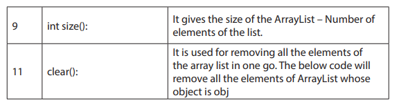
d. Creating, declaring an ArrayList Object
To create an array list, an ArrayList variable is firstly declared and the ArrayList constructor is called to instantiate an ArrayList object and assign it to the variable.
ArrayList signs = new ArrayList();
Here are a few things to note about creating array lists:
• The ArrayList class is in the java.util package, so the program must import
either java.util.ArrayList or java.util.*.
• Unlike an array, an array list doesn’t make the user specify a capacity even
if it is possible.
Example that creates an array list with an initial capacity of 100:
ArrayList signs = new ArrayList(100);
e. Adding Elements
After an array list is created, the add method to add objects to the array list is the
used. An array lists is indexed starting with zero and when it is already at its capacity
when an element is added, the array list automatically expands its capacity.
Example: signs.add(“Peter”);
If a type when is specified during the creationof the array list, the added objects via
the add method must be of the correct type. An object can be inserted at a specific
position in the list by listing the position in the add method.
Syntax: ArrayList<String>nums = new ArrayList<String>();
f. Accessing Elements
To access a specific element in an array list, the get method can be used, which specifies the index value of the element to be retrieved. Here’s a for loop that prints all
the strings in an array list:
for (inti = 0; i<nums.size(); i++)
System.out.println(nums.get(i));
Here the size method is used to set the limit of the for loop’s index variable. The
easiest way to access all the elements in an array list is to use an enhanced “for”
statement, which allows to retrieve the elements without bothering with indexes or
the get method.
For example:
For (String s: nums)
System.out.println(s);
To know the index number of a particular object in an array list a reference to the
object is known, the indexOf method is used.
g. Printing an ArrayList
Arrays are usually useful when working with arbitrarily large number of data having
the same type. It is usually convenient if we can print the contents of an array.
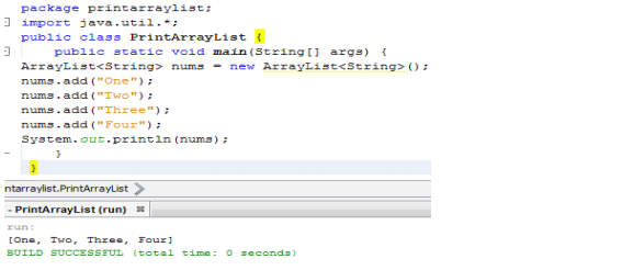
• Print Array In Java Using Default toString()
The toString method of the ArrayList class (as well as other collection classes) is
designed to make it easy to quickly print out the contents of the list. It returns the
contents of the array list enclosed in a set of brackets, with each element value
separated by commas. The toString method of each element is called to obtain the
element value.
Below is a Simple Program That Prints An Array In Java using Arrays.toString().
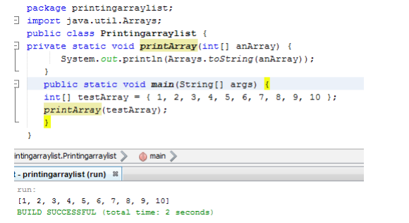
The following is generalArrayList Example in Java
package arraylist1;
importjava.util.*;
public class ArrayList1 {
public static void main(String[] args) {
/*Creation of ArrayList: I’m going to add String elements so I made it of string type */
ArrayList<String>obj = new ArrayList<String>();
/*This is how elements should be added to the array list*/
obj.add(“Peter”);
obj.add(“TOM”);
obj.add(“Jim”);
obj.add(“Alice”);
obj.add(“Sam”);
/* Displaying or Printing an array list element */
System.out.println(“Currently the array list has following elements:”+obj);
/*Add element at the given index*/
obj.add(0, “Kayiranga”);
obj.add(1, “Damas”);
/*Remove elements from array list like this*/
obj.remove(“Peter”);
obj.remove(“Tom”);
System.out.println(“Current array list is:”+obj);
/*Remove element from the given index*/
obj.remove(1);
System.out.println(“Current array list is:”+obj);
}
}
Output:
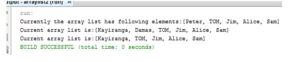
10.2.1.2. Java - LinkedList class
The Linked list implementation of the List interface implements all optional List
operations and permits all elements (including null). In addition to implementing
the List interface, LinkedList provides uniformly named methods to get, remove
and insert an element at the beginning and end of the List. These operations allow
LinkedList to be used as a stack, queue, or double-ended queue (deque). It provides
a linked-list data structure and inherits the AbstractList class.
a. Creating, declaring a LinkedList
As with any other kind of object, creating a linked list is a two-step affair. First, declare a LinkedList variable; then call one of the LinkedList constructors to create the
object, as in this example:
LinkedList officers = new LinkedList
to the variable officers.
Here’s a statement that creates a linked list that holds strings:
LinkedList<String> officers = new LinkedList<String> ();
Then add only String objects to this list.
b. Adding Items to a LinkedList
The LinkedList class gives many ways to add items to the list. The most basic is the
add method, which works pretty much the same way that it does for the ArrayList
class.
Here’s an example:

To insert an object into a specific position into the list, specify the index in the add
method, as in this example:
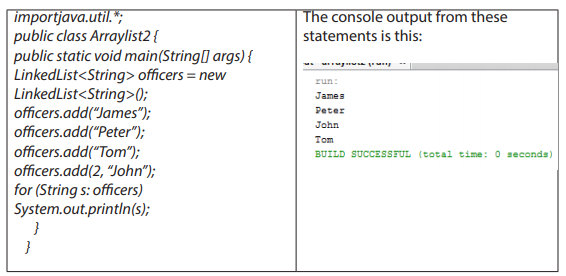
c. Retrieving Items from a LinkedList
Get method is used to retrieve an item based on its index. If an invalid index number
is passed to it, the get method throws the unchecked IndexOutOfBoundsException.
An enhanced “for” loop to retrieve all the items in the linked list can also be used. The
examples in the preceding section use this enhanced for loop to print the contents
of the officers linked list:
for (String s: officers)
System.out.println(s);
Some methods retrieve the first item in the list:
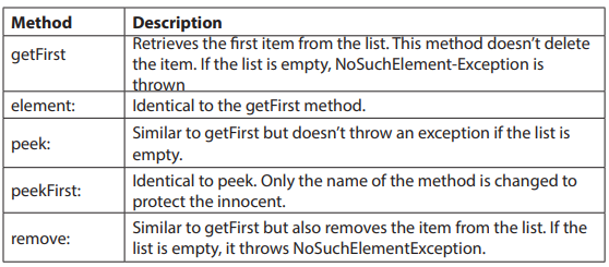
d. Updating LinkedList Items
As with the ArrayList class, the set method can be used to replace an object in a
linked list with another object.
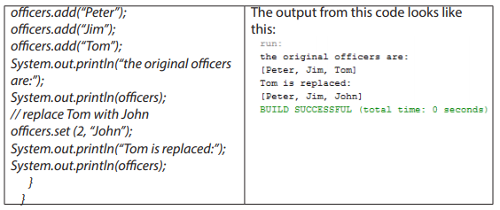
e. Removing LinkedList Items
Several of the methods that retrieve items from a linked list and also remove the
items have been seen. The remove, removeFirst, and poll methods remove the first
item from the list, and the removeLast method removes the last item. Any arbitrary
item can be removed by specifying either its index number or a reference to the
object to be removed on the remove
method. To remove item 3, for example, use a statement like this:
officers.remove(3);
If a reference to the item to be removed is there, use the remove method, like this:
officers.remove(Jim);
To remove all the items from the list, use the clear method:
officers.clear
The following program illustrates several of the methods supported by LinkedList
and support above collection method:
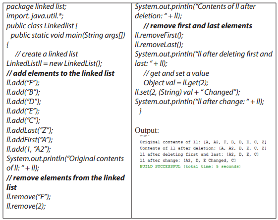
f. Java LinkedList Example: Book
import java.util.*;
class Book {
int id;
String book_title,author,publisher;
int quantity;
public Book(int id, String book_title, String author, String publisher, int quantity) {
this.id = id;
this.book_title = book_title;
this.author = author;
this.publisher = publisher;
this.quantity = quantity;
}
}
public class LinkedListExample {
public static void main(String[] args) {
//Creating list of Books
List<Book> list=new LinkedList<Book>
//Creating Books
Book b1=new Book(101,”Introduction to Java”,”Martin”,10);
Book b2=new Book(102,”Data Communications & Networking”,”James”,”Alph”4);
Book b3=new Book(103,”Operating System”,”John”,”Samuel”,6);
//Adding Books to list
list.add(b1);
list.add(b2);
list.add(b3);
//Traversing list
for(Book b:list){
System.out.println(b.id+” “+b. book_title +” “+b.author+” “+b.publisher+” “+b.quantity);
} } }
10.2.1.3 Java - vector class
Vectors (the java.util.Vector class) are commonly used instead of arrays, because
they expand automatically when new data is added to them. If a primitive type in a
Vector is to be put, put it inside an object (eg, to save an integer value use the Integer class or define your own class).
The java.util. Vector class implements a dynamic array of objects. Similar to an Array,
it contains components that can be accessed using an integer index. The size of a
Vector can grow or shrink as needed to accommodate adding and removing items.
Vector is synchronized. This means that if one thread is working on Vector, no other
thread can get a hold of it. Unlike ArrayList, only one thread can perform an operation on vector at a time.
Class declaration for java.util.Vector class
a. Class constructors
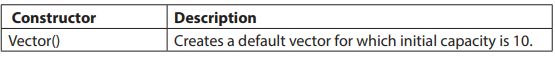
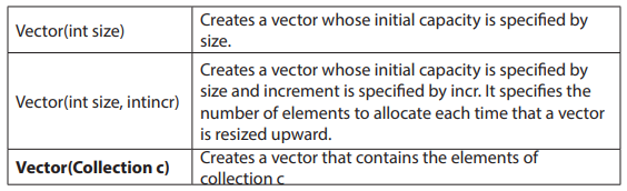
There exist Vector class methods which are used in Java collections. Here is an example of how these methods are used:
Example that can support some of the above said method:
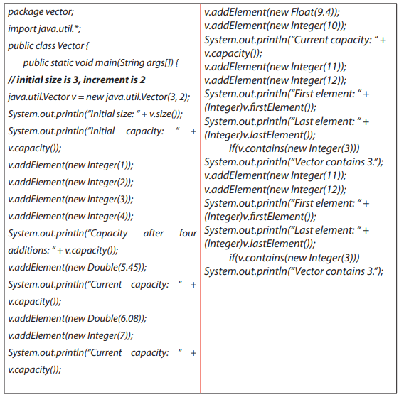
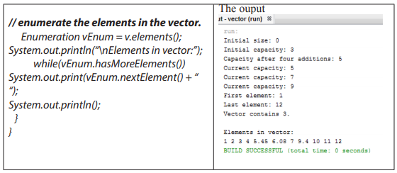
Application Activity 10.2.
1. Discuss when to use ArrayList andLinkedList in Java?
2. Write a program that do the following:
• Create linkedList from linked list with assigned to the variable district.
• Add the following district in the List (Gakenke, Rubavu, Gasabo, Nyagatare,
Nyabihu )
• Add Bugesera District to the front of list and Karongi to the4th position
• Replace Gasabo District with Nyarugenge
• Retrieving the Second District using Index
• Show the Size and Remove the last district in the List
Note: After every operation display output
3. What are similarities and difference between ArrayList and Vector?
10.2.2. Java Collections – Set interface and implementations
Learning Activity 10.3.
Study the following part of Java Program and answer the following?
Set setA = new HashSet ();
String element = "element 1";
setA.add(element);
System.out.println(setA.contains(element));
1. Outline the method used in the above program?
2. What is HashSet in the above program?
3. List and explain Set implementations using by Internet or books help
Basically, a Set is a type of collection that does not allow duplicate elements. That
means an element can only exist once in a Set. It models the set abstraction in
mathematics. A Set is an unordered collection of objects.
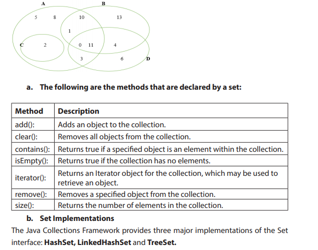
1. Java - HashSet class
This class implements the Set interface backed by a hash table, It creates a collection that uses a hash table for storage. A hash table stores information by using a
mechanism called hashing. In hashing, the informational content of a key is used to
determine a unique value, called its hash code.
The following table lists the constructors associated with Java HashSet:
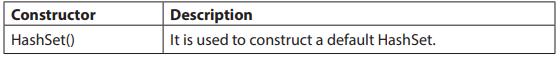
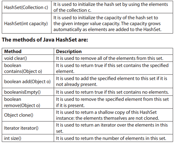

Java HashSet Example: Book
This is a HashSet example where we are adding books to set and printing all the
books.
import java.util.*;
class Book {
int id;
String book_title,author,publisher;
int quantity;
public Book(int id, String book_title, String author, String publisher, int quantity) {
this.id = id;
this.book_title = book_title;
this.author = author; // The body of class constructor
this.publisher = publisher;
this.quantity = quantity;
} }
public class HashSetExample {
public static void main(String[ ] args) {
HashSet<Book> set=new HashSet<Book>();
//Creating Books
Book b1=new Book(101,”Introduction to Java”,”Martin”,10);
Book b2=new Book(102,”Data Communications & Networking”,”James”,”Alph”4);
Book b3=new Book(103,”Operating System”,”John”,”Samuel”,6);
//Adding Books to HashSet
set.add(b1);
set.add(b2);
set.add(b3);
//Traversing HashSet
for(Book b:set){
System.out.println(b.id+” “+b.book_title+” “+b.author+” “+b.publisher+” “+b.quantity; } }
}
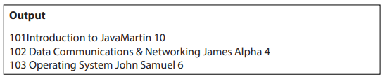
10.2.2.2. Java LinkedHashSet Class
Java LinkedHashSet class is a Hash table and Linked list implementation of the set
interface. It inherits HashSet class and implements Set interface.
The important points about Java LinkedHashSet class are:
• Contains unique elements only like HashSet.
• Provides all optional set operations, and permits null elements.
• Maintains insertion order.
LinkedHashSet class is declared like this:
public class LinkedHashSet<E> extends HashSet<E> implements Set<E>, Cloneable, serializable
LinkedHashSet<String>hs = new LinkedHashSet<String>();
Constructors of Java LinkedHashSet class
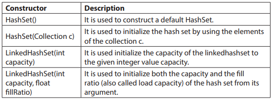
Unlike HashSet, LinkedHashSet builds a link-list over the hash table for better efficiency in insertion and deletion (in the expense of more complex structure). It maintains its elements in the insertion-order (i.e., order of add()).
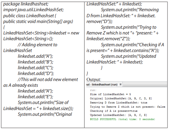
Java LinkedHashSet Example: Book
import java.util.*;
class Book {
int id;
String book_title,author,publisher;
int quantity;
public Book(int id, String book_title, String author, String publisher, int quantity) {
this.id = id;
this.book_title = book_title;
this.author = author;
this.publisher = publisher;
this.quantity = quantity;
}
} public class LinkedHashSetExample {
public static void main(String[] args) {
LinkedHashSet<Book> hs=new LinkedHashSet<Book>();
//Creating Books
Book b1=new Book(101,”Introduction to Java”,”Martin”,10);
Book b2=new Book(102,”Data Communications & Networking”,”James”,”Alph”4);
Book b3=new Book(103,”Operating System”,”John”,”Samuel”,6);
//Adding Books to hash table
hs.add(b1);
hs.add(b2);
hs.add(b3);
//Traversing hash table
for(Book b:hs){
System.out.println(b.id+” “+b. book_title +” “+b.author+” “+b.publisher+” “+b.quantity);
} }
}
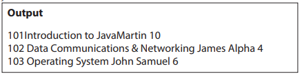
10.2.3. Java-class TreeSet class
The Java TreeSet class implements the Set interface that uses a tree for storage. It
inherits AbstractSet class and implements NavigableSet interface. The objects of
TreeSet class are stored in ascending order.
a. Constructors of Java TreeSet class
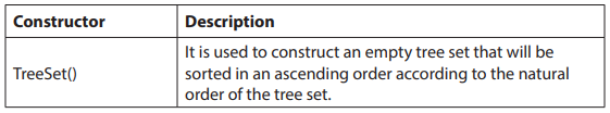
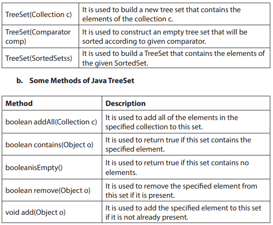
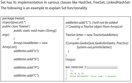
10.2.2.4. The difference between Set and List is:
• List is a collection class which extends AbstractList class whereas Set is a
collection class which extends AbstractSet class, but both implements
Collection interface.
• List interface allows duplicate values (elements) whereas Set interface does
not allow duplicate values which means that List can contain duplicate
elements whereas Set contains unique elements only
• Set is unordered while List is ordered. List maintains the order in which the
objects are added.
Application Activity 10.3.
1. What is the output of this program?
importjava.util.*;
class Output
{
public static void main(String args[])
{
HashSetobj = new HashSet();
obj.add("A");
obj.add("B");
obj.add("C");
System.out.println(obj + " " + obj.size());
}
}
2. What is the difference between a HashSet and a TreeSet?
10.2.3Java Collections – Map interface
Learning Activity 10.4.
Study the following part of Java Program and answer the following questions?
Map<Integer, String>mapmarks = new HashMap<>();
mapmarks.put(80, "tom");
mapmarks.put(75, "Alice");
mapmarks.put(65, "Antoine");
mapmarks.put(50, "peter");
System.out.println(mapmarks);
1. Outline the method used in the above program;
2. What is HashMap in the above program?
3. List and explain Map implementations by using Internet connection or
books.
4. Analyze the program and give the output.
A Map is a collection or an object that maps keys to values. A map cannot contain duplicate keys: Each key can map to at most one value. Maps are perfectly for key-value
association mapping such as dictionaries. Use Maps when there is a need to retrieve
and update elements by keys, or perform lookups by keys.
A Map is an object that maps keys to values or is a collection of attribute-value pairs.
It models the function abstraction in mathematics. The following picture illustrates
a map:

Note that a Map is not considered to be a true collection, as the Map interface does not extend the Collection interface.
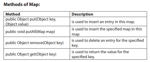

a. Map implementation
The Java platform contains three general-purpose Map implementations: HashMap,
TreeMap, and LinkedHashMap. Their behavior and performance are precisely
analogous to HashSet, TreeSet, and LinkedHashSet, as described in The Set Interface
section. A Map cannot contain duplicate keys and each key can map to at most
one value. Some implementations allow null key and null value (HashMap and
LinkedHashMap) but some does not (TreeMap). The order of a map depends on
specific implementations, e.gTreeMap and LinkedHashMap have predictable order,
while HashMap does not.
10.2.3.1. Java - HashMap Class
This implementation uses a hash table as the underlying data structure. It implements
all of the Map operations and allows null values and one null key. This class is roughly
equivalent to Hashtable - a legacy data structure before Java Collections Framework,
but it is not synchronized and permits nulls. HashMap does not guarantee the order
of its key-value elements. Therefore, consider to use a HashMap when order does
not matter and nulls are acceptable.
Note: HashMap does not maintain any order neither based on key nor on basis of
value, If the keys is wanted to be maintained in a sorted order, TreeMap needs to be
used.
The HashMap class uses a hashtable to implement the Map interface. This allows the
execution time of basic operations, such as get
for large sets.
The following is the list of constructors supported by the HashMap class.
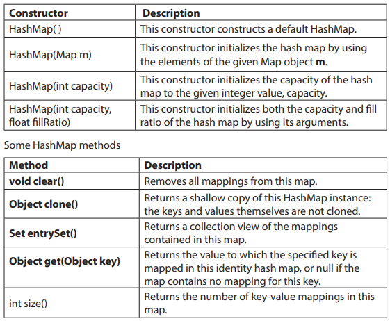
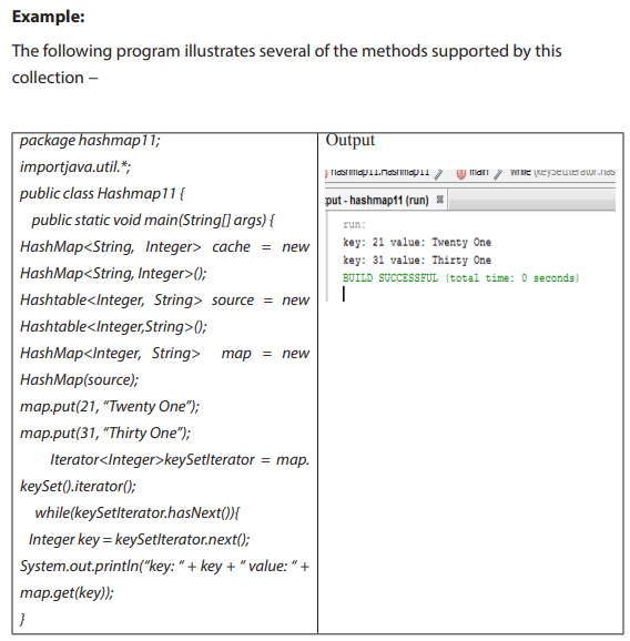
10.2.3.2. Java- LinkedHashMap
Java LinkedHashMap class is Hash table and Linked list implementation of the Map
interface, with predictable iteration order. It inherits HashMap class and implements
the Map interface.
The important points about Java LinkedHashMap class are:
• A LinkedHashMap contains values based on the key.
• It contains only unique elements.
• It may have one null key and multiple null values.
• It is same as HashMap instead maintains insertion order.
Java LinkedHashMap Example: Creating and traversing the book
importjava.util.*;
class Book {
int id;
String book_title,author,publisher;
int quantity;
public Book(int id, String book_title, String author, String publisher, int quantity) {
this.id = id;
this. book_title = book_title;
this.author = author;
this.publisher = publisher;
this.quantity = quantity;
}
}
public class MapExample {
public static void main(String[] args) {
//Creating map of Books
Map<Integer,Book> map=new LinkedHashMap<Integer,Book>();
//Creating Books
Book b1=new Book(101,”Let us C”,”Yashwant Kanetkar”,”BPB”,8);
Book b2=new Book(102,”Data Communications & Networking”,”Forouzan”,”Mc Graw Hill”,4);
Book b3=new Book(103,”Operating System”,”Galvin”,”Wiley”,6);
//Adding Books to map
map.put(2,b2);
map.put(1,b1);
map.put(3,b3);
//Traversing map
for(Map.Entry<Integer, Book>entry:map.entrySet()){
int key=entry.getKey();
Book b=entry.getValue();
System.out.println(key+” Details:”);
System.out.println(b.id+” “+b. book_title +” “+b.author+” “+b.publisher+” “+b.quantity);
} }
}
10.2.3.3. Java – TreeMap class
This implementation uses a red-black tree as the underlying data structure. A TreeMap is sorted according to the natural ordering of its keys, or by a Comparator provided at creation time. This implementation does not allow nulls. So consider using a
TreeMap when Map is wanted to sort its key-value pairs by the natural order of the
keys (e.g. alphabetic order
• Difference between Map and Set
The Map object has unique keys each containing some value, while Set contain only
unique values.
Application Activity 10.4.
1. Describe various implementations of the Map interface and their use
case differences.
2. How is HashMap implemented in Java? How does its implementation
use hashCode and equals methods of objects?
3. Write a program to do the following :
• create HashMap from copying data from another Map
• adding key and value in Java HashMap
• Retrieving value from HashMap
• Show the Size and Clear value in HashMap
• Sorting HashMap on keys and values entered using TreeMap.
10.2.4. Java collections – Queue interface
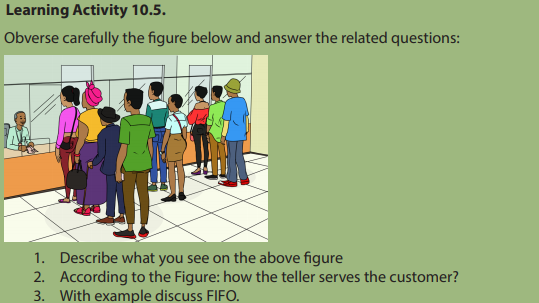
a. Definition
Queue means ‘waiting line’. A Queue is designed in such a way so that the elements
added to it are placed at the end of Queue and removed from the beginning of
Queue. In programming a Queue is a collection or data structure for holding
elements prior to processing like queues in real-life scenarios.
b. First In First Out or FIFO
Let’s consider that a queue holds a list of waiting customers in a bank’s counter. Each
customer is served one after another, by following their orders of arriving. The first
customer comes is served first, and after him is the 2nd, the 3rd, and so on. When
the customer is served, he or she leaves the counter (removed from the queue), and
the next customer is picked to be served next. Other customers who come later are
added to the end of the queue. This processing is called First In First Out or FIFO. The
FIFO principle is thatItems stored first are retrieved first.
c. Queue methods
The Queue interface defines some methods for acting on the first element of the
list, which differ in the way they behave, and the result they provide.
• peek()
In computer science, peek is an operation on certain abstract data types, specifically
sequential collections such as stacks and queues, which returns the value of the top
(“front”) of the collection without removing the element from the collection. It thus
returns the same value as operations such as “pop” or “dequeue”, but does not modify the data. If the list is empty, it returns null.
Key points:
peek ():
• Retrieves, but does not remove, the head of this queue, or returns null if
this queue is empty.
• Returns: the head of this queue, or null if this queue is empty
• element()
The element() method behaves like peek(), so it again retrieves the value of the first
element without removing it. Unlike peek(), however, if the list is empty element()
throws a NoSuchElementException
• poll()
The poll() method retrieves the value of the first element of the queue by removing
it from the queue . At each invocation it removes the first element of the list and if
the list is already empty it returns null but does not throw any exception.
• remove()
The remove() method behaves as the poll() method, so it removes the first element
of the list and if the list is empty it throws a NoSuchElementException
• boolean add():
This method adds the specified element at the end of Queue and returns true if
the element is added successfully or false if the element is not added that basically
happens when the Queue is at its max capacity and cannot take any more elements.
d. Queue Implementations
Queue interface in Java collections has two implementations: LinkedList and
Priority Queue.
• LinkedList is a standard queue implementation. Queue q1 = new LinkedList ();
• Priority Queue stores its elements internally according to their natural order.
PriorityQueue class is a priority queue based on the heap data structure. By
default, we know that Queue follows First-In-First-Out model but sometimes we
need to process the objects in the queue based on the priority. That is when Java
PriorityQueue is used. For example, let’s say we have an application that generates
stocks reports for daily trading session. This application processes a lot of data and
takes time to process it. So, customers are sending request to the application that
is actually getting queued, but we want to process premium customers first and
standard customers after them. So in this case PriorityQueue implementation in java
can be really helpful. Example of how to create a Queue instance:
Queue q2 = new PriorityQueue();
1. Adding and Accessing Elements
To add elements to a Queue you call its add() method. This method is inherited from
the Collection interface.
Here are examples:
Queue queueA = new LinkedList ();
queueA.add(“element 1”);
queueA.add(“element 2”);
The order in which the elements added to the Queue are stored internally, depends
on the implementation. The same is true for the order in which elements are retrieved from the queue. You can peek at the element at the head of the queue without taking the element out of the queue. This is done via the element() method.
Here is how that looks: Object firstElement = queueA.element();
2. Removing Elements
To remove elements from a queue, you call the remove() method. This method removes the element at the head of the queue. In most Queue implementations the
head and tail of the queue are at opposite ends. It is possible, however, to implement the Queue interface so that the head and tail of the queue is in the same end.
In that case you would have a stack.
Remove example: Object firstElement = queueA.remove();
3. Generic Queue
By default, any Object can be put into a Queue, Java Generics makes it possible to
limit the types of object you can insert into a Queue.
Example: Queue<MyObject> queue = new LinkedList<MyObject> ();
Another type of collection that allows to add objects to the end of the collection and
remove them from the top. Queues are commonly used in all sorts of applications,
from data processing applications to sophisticated networking systems. This queue
class is named GenQueue and has the following methods:
• enqueue: This method adds an object to the end of the queue. (insertion
of element in Queue)
• dequeue: This method retrieves the first item from the queue. The item is
removed from the queue in the process. (Deletion of element in Queue)
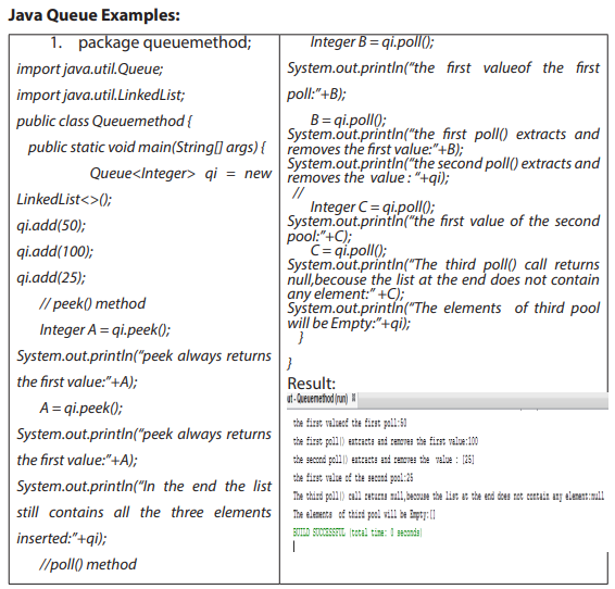
2. Removing
packagequeuemethod;
importjava.util.Queue;
importjava.util.LinkedList;
public class Queuemethod {
public static void main(String[] args) {
Queue<Integer> qi = new LinkedList<>();
qi.add(50);
qi.add(100);
Integer A = qi.remove();
System.out.println(“the first value is:”+A);
A = qi.remove();
System.out.println(“after remove the first value is:”+A);
A = qi.remove();
System.out.println(A);
System.out.println(qi);
}
}
From the following result, the third remove() call throws a NoSuchElementException
because it has been executed on an empty queue. This behavior, is what makes it
different from the poll() method.

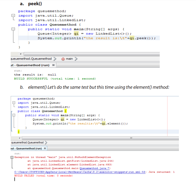
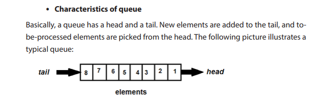

The Dequeu interface abstracts this kind of queue, and it is a sub interface of the
Queue interface. And the LinkedList class is a well-known implementation. Some
implementations accept null elements, some do not. Queue does allow duplicate
elements, because the primary characteristic of queue is maintaining elements by
their insertion order. Duplicate elements in terms of equals contract are considered
distinct in terms of queue, as there are no two elements having same ordering.
Additionally, the Java Collection Framework provides the BlockingQueue interface
that abstracts queues which can be used in concurrent (multi-threading) context.
A blocking queue waits for the queue to become non-empty when retrieving an element and waits for space become available in the queue when storing an element.
Similarly, the BlockingDeque interface is blocking queue for double ended queues.
Application Activity 10.5.
1. What is Java Priority Queue?
2. Explain the method used in Queue interface and write a program that
those are applicable.
3. What is the difference between poll() and remove() in a PriorityQueue?
4. Give a question where students write a program by applied the queue
interface
5. Write a program and ask students to interpret is an give output
10.2.5 Java collections – Stack
Learning Activity 10.6.
Obverse carefully the following figure and respond to the asked questions:

1. Describe what you see on the above figure
2. According to the Figure: how the teller serves the customer?
3. With example discuss FIFO.
A stack is a container of objects that are inserted and removed according to the lastin first-out (LIFO) principle. In computer science, a stack is an abstract data type that
serves as a collection of elements, with two principal operations:
• push, which adds an element to the collection
• pop, which removes the most recently added element that was not yet removed.
a. Operations on Stack
The Push operation stores something on the top of the stack and the Pop operation
retrieves something from the top of the stack.
The following figures represent the stack operations.
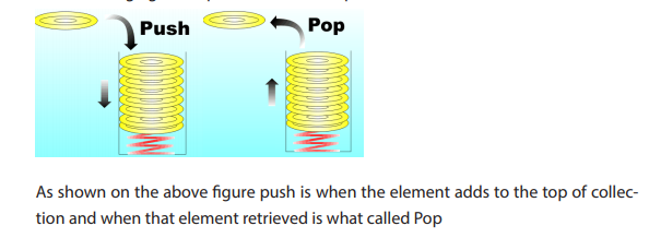

b. LIFO Stack (Last In First Out)
A stack is a last-in-first-out (LIFO) data structure; in other words, the first thing to be
removed is the item most recently added. A push is when you put a new item onto
the stack, and a pop is when you take it off.
Some Applications of stack:
• The simplest application of a stack is to reverse a word. You push a given
word to stack - letter by letter - and then pop letters from the stack.
• Another application is an “undo” mechanism in text editors; this operation
is accomplished by keeping all text changes in a stack.
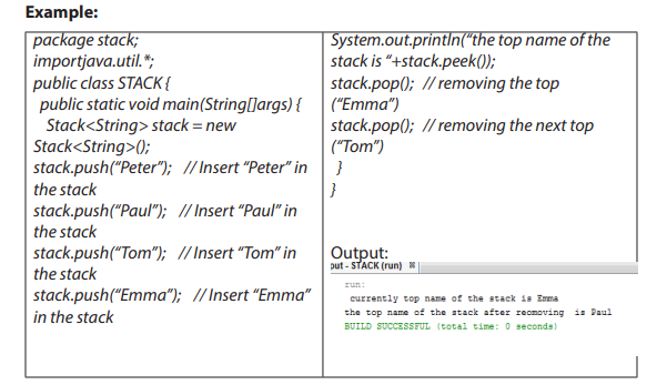
Application activity 10.6
1. Give the output of the following program:
Packagestackimpl;
Importjava.util.Stack;
public class StackImpl<E>
{
private Stack<E> stack;
publicStackImpl()
{
stack = new Stack<E>();
}
publicboolean empty()
{
returnstack.empty();
}
public E peek()
{
returnstack.peek();
}
public E pop()
{
returnstack.pop();
}
public E push(E item)
{
returnstack.push(item);
}
publicint search(Object o)
{
returnstack.search(o);
}
public static void main(String...arg)
{
StackImpl<Integer> stack = new
StackImpl<Integer>();
System.out.println(“element pushed :
“ + stack.push(3));
System.out.println(“element pushed :
“ + stack.push(4));
System.out.println(“element pushed
: “ + stack.push(-19));
System.out.println(“element pushed
: “ + stack.push(349));
System.out.println(“element pushed
: “ + stack.push(35));
System.out.println(“element poped :
“ + stack.pop());
System.out.println(“element poped :
“ + stack.pop());
System.out.println(“Element peek : “
+ stack.peek());
System.out.println(“position of
element 349 “ + stack.search(3));
while (!stack.empty())
{
System.out.println(“element poped :
“ + stack.pop());
}
}
}
2. What is the output of this
program?
importjava.util.*;
class stack
{
public static void main(String args[])
{
Stack obj = new Stack();
obj.push(new Integer(3));
obj.push(new Integer(2));
obj.pop();
obj.push(new Integer(5));
System.out.println(obj);
}
}
10.2.6. Java collection – Tree
Learning Activity 10.6.
Obverse carefully this figure and answer to the following questions:
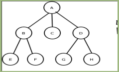
1. What is a node in tree?
2. Illustrate relationship between A and B; E and F?
3. Draw your school organization structure?
a. Definition
A tree, T, by definition, is a non-empty set of elements where one of these elements
is called the root and the remaining elements are partitioned further into sub trees
of T.
A Tree is a non-linear data structure where data objects are organized in terms of
hierarchical relationship. The structure is non-linear in the sense that, unlike simple
array and linked list implementation, data in a tree is not organized linearly.
A tree data structure is a powerful tool for organizing data objects based on keys.
it can be defined as a collection of entities called nodes linked together to simulate
a hierarchy. It is equally useful for organizing multiple data objects in terms of hierarchical relationships (think of a “family tree”, where the children are grouped under
their parents in the tree).
a. Node in a Tree
Each data element is stored in a structure called a node. The topmost or starting
node of the (inverted) tree is called the root node. All nodes are linked with an edge
and form hierarchical sub trees beginning with the root node.
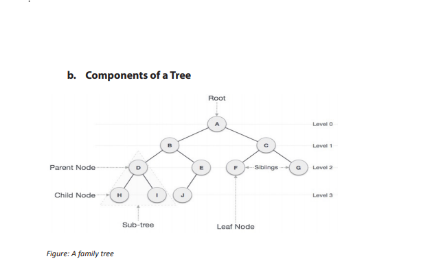
The descendants of A are arranged in a hierarchical fashion. A, at the top of the (inverted) tree, represents the root node. A’s children are B and C. B’s children are D and
E. C’s children are F and G. F has no children, E has one, and D has two. They are listed
in the same hierarchical manner. The link between each of the nodes is called an
edge. This link signifies the relationship that one node has with another, such as B’s
children, F’s sibling, A’s descendant, and so forth. Sometimes, the ending nodes of
the tree are called leaves.
• Node: stores a data element.
• Parent: single node that directly precedes a Node, all nodes have one
parent except root (has 0)
• Child: one or more nodes that directly follow a node
• Ancestor: any node which precedes a node. itself, its parent, or an
ancestor of its parent
• Descendent: any node which follows a node. itself, its child, or a descendent
of its child
• Root: The node at the top of the tree is called root. There is only one root
per tree and one path from the root node to any node.
More Tree Terminology
• Leaf (external) node: node with no children
• Internal node: non-leaf node
• Siblings: nodes which share same parent
• Subtree: a node and all its descendants. Ignoring the node’s parent, this is
itself a tree
• Ordered tree: tree with defined order of: tree with defined order of children.
Enables ordered traversal
• Binary tree: each node can have at least two children, ordered tree with up
to two. children per node
• Path: Path refers to the sequence of nodes along the edges of a tree.
• Visiting: Visiting refers to checking the value of a node when control is on
the node.
• Traversing: Traversing means passing through nodes in a specific order.
• Levels: Level of a node represents the generation of a node. If the root node
is at level 0, then its next child node is at level 1, its grandchild is at level 2,
and so on.
c. Advantages of a tree (Order of items in a tree)
The Tree data structure is useful on occasions where linear representation of data
does not suffice, such as creating a family tree. Java provides two in-built classes,
TreeSetand TreeMap, in Java Collection Framework that cater to the needs of the
programmer to describe data elements in the aforesaid form.
Treemap main advantage is that it allows to store the key-value mappings in a sorted order
Some Applications of Trees
• Storing naturally hierarchical data eg. File system
• Trees can hold objects that are sorted by their keys
• An operating system maintains a disk’s file system as a tree, where file
folders act as tree nodes
d. Storing elements in a tree
When an object contains two pointers to objects of the same type, structures can be
created that are much more complicated than linked lists, the most basic and useful
structures of this type used is binary trees. Each of the objects in a binary tree contains two pointers, typically called left and right.
• Binary Tree
A binary tree is a recursive data structure where each node can have 2 children at
most. A common type of binary tree is a binary search tree, in which every node
has a value that is greater than or equal to the node values in the left sub-tree, and
less than or equal to the node values in the right sub-tree. A binary tree of integers
would be made up of objects of the following type:
classTreeNode {
int item; // The data in this node.
TreeNode left; // Pointer to the left subtree.
TreeNode right; // Pointer to the right subtree.
}
e. Data representation
The simplest data representation is Nodes and Links; so a list of Nodes such as
1,2,3,4,5, and a list of links such as 1:2, 1:3, 2:4, 2:5 would represent the tree below:

f. Traversing the Tree
• Depth-First Search: is a type of traversal that goes deep as much as possible
in every child before exploring the next sibling.
here are several ways to perform a depth-first search: in-order, pre-order and post-order.
Example:
privateBinaryTreecreateBinaryTree() {
BinaryTreebt = new BinaryTree();
bt.add(6);
bt.add(4);
bt.add(8);
bt.add(3);
bt.add(5);
bt.add(7);
bt.add(9);
returnbt;
}
The in-order traversal in the console output: 3 4 5 6 7 8 9
The pre-order traversal in the console output: 6 4 3 5 8 7 9
Here are the nodes in post-order: 3 5 4 7 9 8 6
• Breadth-First Search: This is another common type of traversal that visits
all the nodes of a level before going to the next level.
In this case, the order of the nodes will be: 6 4 8 3 5 7 9
Example of TreeMap that store the element:
importjava.util.Map;
public class TreeMap {
public static void main(String[] args) {
Map<Integer, String >empInfo = new TreeMap<Integer,String>();
empInfo.put(20,”kalisa” );
empInfo.put(4,”Emmy” );
empInfo.put(9,”Diane” );
empInfo.put(15,”Karera” );
System.out.println(empInfo);
}
}
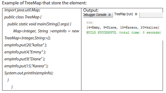
Application Activity 10.7.
1. 1)List the nodes of the tree below in preorder, post order, and breadthfirst order
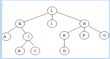
2. Write an example showing basic operations on TreeMap like creating
an object, adding key-value pair objects, getting value by passing key
object, checking whether the map has elements or not, deleting specific
entry, and size of the TreeMap.
END UNIT ASSSSMENT
1. Describe the Collections type hierarchy. What are the main interfaces, and
what are the differences between them?
2. What is the difference between: List and Set? List and Map? ArrayList and
Vector?
3. How to create a List instance?
4. What is Queue and Stack, list their differences?
5. Write a Java program to insert an element into the array list at the first
position.
6. Write a Java program to search a key in a Tree Map
UNIT 11: JAVA ENTERPRISE WEB APPLICATIONS
Key unit competency
To be able to design and run a java enterprise web application
Introductory Activity
Observe the figure below and answer questions:
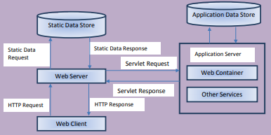
1. Describe what you see.
2. Give a meaning of each arrow in the figure.
3. Explain the whole process illustrated in the figure above.
4. Describe a web server.
5. Describe a web container.
11.1 Tomcat
Activity 11.1.
Describe and illustrate the difference between web server and application server?
11.1.1. Definition of Apache Tomcat:
Apache Tomcat is a web server and application server that is used to serve Java
applications. Tomcat employs a hierarchical and modular architecture as shown
below:
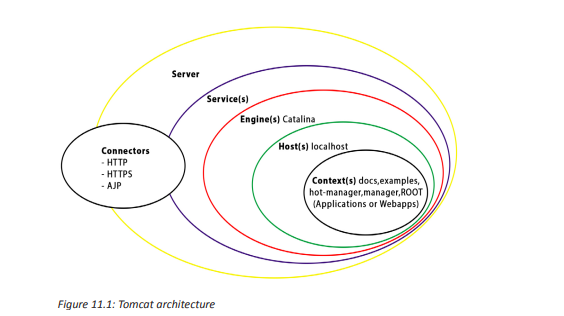
11.1.2. Terms
a. Server
In the Tomcat world, a Server represents the whole container. Tomcat provides a
default implementation of the Server interface, and this is rarely customized by
users.
b. Service
A Service is an intermediate component which lives inside a Server and ties one or
more Connectors to exactly one Engine.
c. Engine
An Engine represents request processing channel for a specific Service. As a Service
may have multiple Connectors, the Engine received and processes all requests from
these connectors, handing the response back to the appropriate connector for
transmission to the client.
d. Host
A Host is an association of a network name, e.g. www.yourcompany.com, to the
Tomcat server. An Engine may contain multiple hosts, and the Host element also
supports network aliases such as yourcompany.com and abc.yourcompany.com.
e. Connector
A Connector handles communications with the client. Connectors provide
instructions for the ports an application server listens to for incoming requests with
incoming requests being directed to configured web application.
f. Context
A Context represents a web application. A Host may contain multiple contexts,
each with a unique path. The Context interface may be implemented to create
custom Contexts, but this is rarely the case because the Standard Context provides
significant additional functionality.
11.1.3. The components of Tomcat are:
Tomcat itself is comprised of three main components: Jasper, Catalina, and Coyote.
These components combined allow for the parsing and compilation of Java Server
Pages into java servlet code, the delivery of these servlets, and request processing.
a. Jasper
Jasper is Apache Tomcat’s Java Server Pages Engine. Jasper describes JSP files
compiling them into Java code as servlets to be handled by Catalina. At runtime,
Jasper detects changes to JSP files and recompiles them.
b. Catalina
Catalina is Apache Tomcat’s servlet container. Catalina implements the specifications
for servlet and Java Server Pages (JSP).
c. Coyote
Coyote is Apache Tomcat’s HTTP Connector component supporting the HTTP 1.1
protocol. Coyote listens for incoming connections on configured TCP ports on the
server and forwards requests to the Tomcat Engine for processing and returning a
response to the requesting client.
Application Activity 11.1.
1. Describe what Tomcat is?
2. Explain the architecture of Tomcat.
3. Explain the role of each one the main components of Tomcat.
11.2. Installation and configuration of tomcat configuration
directory
Activity 11.2.
Switch on computers in your school computer lab and answer the following
questions:
1. Examine the type and version of operating system running on your
computer.
2. Observe the web server software installed on your computer.
11.2.1. Installing Tomcat
a. Requirements for Installing
To install and configure Tomcat, first download the Latest version of Tomcat and
Netbeans with Java Development Kit (JDK). You should choose the appropriate
downloads based on your operating system.
b. Installing Tomcat Using Windows Service Installer
• The first thing you need to do is install the NetBeans with Java Development
Kit (JDK)
• Download the Apache Tomcat Windows service installer from the Tomcat
download page.
In our case we are going to install Tomcat version 9.0.6. Follow the steps, choose the
installation location, and the installer will take care of extracting and copying files
to correct directory, and configuring Environment variables and service properties.
Figures below show the running Tomcat installer for Windows.
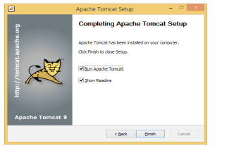
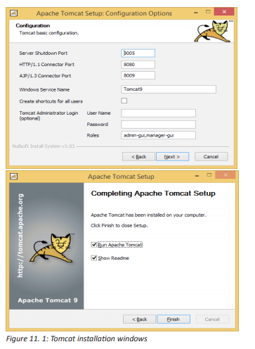
c. Testing Your Tomcat Installation
To test the Tomcat installation, you need to first start the Tomcat server using a folder
which is placed in your Windows Start menu with shortcuts that allow you to start
and stop your Tomcat server from there.
Once Tomcat has started, open your browser to the following URL: http://
localhost:8080/
You should see a page similar to that shown in Figure 11-3.

11.2.2. Configuration of tomcat configuration directory
This directory contains all the configuration files for the Tomcat server. The most
important ones are:
• Server.xml
• Tomcat-user.xml[add user]
• Web.xml
• Contex.xml
a. Server.xml
The main Tomcat configuration file is server.xml, located in conf directory.
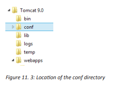
The main Tomcat elements like engines, hosts, and contexts are configured here. This
file is located in the CATALINA_HOME/conf directory and can be considered the heart
of Tomcat. It allows you to completely configure Tomcat using XML configuration
elements. Tomcat loads the configuration from server.xml file at startup, and any
changes to this file require server restart.
CATALINA_HOME: This represents the root of your Tomcat installation. When we
say, “This information can be found in your $CATALINA_HOME/README.txt file” we
mean to look at the README.txt file at the root of your Tomcat install.
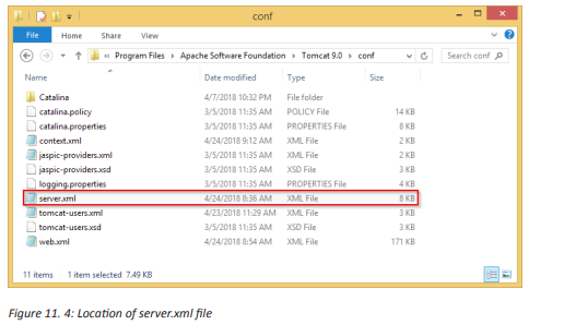
The default server.xml is reproduced as follows (after removing the comments and
minor touch-ups):
<?xml version=”1.0” encoding=”UTF-8”?>
<Server port=”8005” shutdown=”SHUTDOWN”>
<Listener className=”org.apache.catalina.startup.VersionLoggerListener” />
<Listener className=”org.apache.catalina.core.AprLifecycleListener” SSLEngine=”on” />
<Listener className=”org.apache.catalina.core.JreMemoryLeakPreventionListener” />
<Listener className=”org.apache.catalina.mbeans.GlobalResourcesLifecycleListener” />
<Listener className=”org.apache.catalina.core.ThreadLocalLeakPreventionListener” />
<GlobalNamingResources>
<Resource name=”UserDatabase” auth=”Container”
type=”org.apache.catalina.UserDatabase”
description=”User database that can be updated and saved”
factory=”org.apache.catalina.users.MemoryUserDatabaseFactory”
pathname=”conf/tomcat-users.xml” />
</GlobalNamingResources>
<Service name=”Catalina”>
<Connector port=”8080” protocol=”HTTP/1.1”
connectionTimeout=”20000”
redirectPort=”8443” />
<Connector port=”8009” protocol=”AJP/1.3” redirectPort=”8443” />
<Engine name=”Catalina” defaultHost=”localhost”>
<Realm className=”org.apache.catalina.realm.LockOutRealm”>
<Realm className=”org.apache.catalina.realm.UserDatabaseRealm”
resourceName=”UserDatabase”/>
</Realm>
<Host name=”localhost” appBase=”webapps”
unpackWARs=”true” autoDeploy=”true”>
<Valve className=”org.apache.catalina.valves.AccessLogValve” directory=”logs”
prefix=”localhost_access_log” suffix=”.txt”
pattern=”%h %l %u %t "%r" %s %b” />
</Host>
</Engine>
</Service>
</Server>
Understanding codes
• Server
Server (Line 2) is top component, representing an instance of Tomcat. It can contains
one or more services, each with its own engines and connectors.
<Server port=”8005” shutdown=”SHUTDOWN”>
• Common Attributes
• className - Java class name of the implementation to use. This class
must implement the org.apache.catalina.Server interface.
If no class name is specified, the standard implementation will be used.
• Address - The TCP/IP address on which this server waits for a shutdown
command. If no address is specified, localhost is used.
• Port - The TCP/IP port number on which this server waits for a shutdown
command. Set to -1 to disable the shutdown port.
• Shutdown - The command string that must be received via a TCP/IP
connection to the specified port number, in order to shut down Tomcat.
• Listeners
The Server contains several Listeners (Lines 3-7). A Listener element defines a
component that performs actions when specific events occur, usually Tomcat
starting or Tomcat stopping.
For example the Version Logging Lifecycle Listener logs Tomcat, Java and
operating system information when Tomcat starts.
• Global Naming Resources
The element (Line 9-15) defines the JNDI (Java Naming and Directory Interface)
resources, that allows Java software clients to discover and look up data and objects
via a name. The default configuration defines a JNDI name called UserDatabase via
the element (Line 10-14), which is a memory-based database for user authentication
loaded from conf/tomcat-users.xml.
<GlobalNamingResources>
<Resource name=”UserDatabase” auth=”Container”
type=”org.apache.catalina.UserDatabase”
description=”User database that can be updated and saved”
factory=”org.apache.catalina.users.MemoryUserDatabaseFactory”
pathname=”conf/tomcat-users.xml” />
</GlobalNamingResources>
You can define other global resource JNDI such as MySQL database to implement
connection pooling.
• Services
A Service associates one or more Connectors to an Engine. The default configuration
defines a Service called “Catalina”, and associates two Connectors: HTTP and AJP to
the Engine.
<Service name=”Catalina”>
• Connectors
A Connector is associated with a TCP port to handle communications between the
Service and the clients. The default configuration defines two Connectors: HTTP/1.1:
Handle HTTP communication and enable Tomcat to be an HTTP server. Clients can
issue HTTP requests to the server via this Connector, and receive the HTTP response
messages.
<Connector port=”8080” protocol=”HTTP/1.1”
connectionTimeout=”20000”
redirectPort=”8443” />
The default chooses TCP port 8080 to run the Tomcat HTTP server, which is different
from the default port number of 80 for HTTP production server. You can choose any
number between 1024 to 65535, which is not used by any application to run your
Tomcat server.
The connection Timeout attribute define the number of milliseconds this connector
will wait, after accepting a connection, for the request URI line (request message) to
be presented. The default is 20 seconds.
The redirect attribute re-directs the Secure Sockets Layer (SSL) requests to TCP port
8443. AJP/1.3: Apache JServ Protocol connector to handle communication between
Tomcat server and Apache HTTP server.
<Connector port=”8009” protocol=”AJP/1.3” redirectPort=”8443” />
You could run Tomcat and Apache HTTP servers together, and let the Apache HTTP
server handles static requests and PHP; while Tomcat server handles the Java Servlet/
JSP.
• Containers
Tomcat refers to Engine, Host, Context, and Cluster, as container. The highest-level
is Engine; while the lowest-level is Context. Certain components, such as Realm and
Valve, can be placed in a container.
• Engine
A Engine is the highest-level of a container. It can contains one or more Hosts. You
could configure a Tomcat server to run on several hostnames, known as virtual host.
<Engine name=”Catalina” defaultHost=”localhost”>
The Catalina Engine receives HTTP requests from the HTTP connector, and direct
them to the correct host based on the hostname/IP address in the request header.
• Realm
A Realm is a database of user, password, and role for authentication (i.e., access
control). You can define Realm for any container, such as Engine, Host, and Context,
and Cluster.
<Realm className=”org.apache.catalina.realm.LockOutRealm”>
<Realm className=”org.apache.catalina.realm.UserDatabaseRealm”
resourceName=”UserDatabase”/>
</Realm>
The default configuration defines a Realm (UserDatabaseRealm) for the Catalina
Engine, to perform user authentication for accessing this engine. It uses the
JNDI name UserDatabase defined in the GlobalNamingResources. Besides the
UserDatabaseRealm, there are: JDBCRealm (for authenticating users to connect to a
relational database via the JDBC driver); DataSourceRealm (to connect to a DataSource
via JNDI; JNDIRealm (to connect to an LDAP directory); and MemoryRealm (to load
an XML file in memory).
• Hosts
A Host defines a virtual host under the Engine, which can in turn support many
Contexts (webapps).
<Host name=”localhost” appBase=”webapps”
unpackWARs=”true” autoDeploy=”true”>
The default configuration define one host called localhost. The appBase attribute
defines the base directory of all the webapps, in this case, webapps. By default, each
webapp’s URL is the same as its directory name. For example, the default Tomcat
installation provides four webapps: docs, examples, host-manager and manager
under the webapps directory. The only exception is ROOT, which is identified by an
empty string. That is, its URL is https://localhost:8080/. The unpackWARs specifies
whether WAR-file dropped into the webapps directory shall be unzipped. For
unpackWARs=”false”, Tomcat will run the application from the WAR-file directly,
without unpacking, which could mean slower execution. The autoDeploy attribute
specifies whether to deploy application dropped into the webapps directory
automatically.
• Valve
A Valve can intercept HTTP requests before forwarding them to the applications, for
pre-processing the requests. A Valve can be defined for any container, such as Engine,
Host, and Context, and Cluster. In the default configuration, the AccessLogValve
intercepts an HTTP request and creates a log entry in the log file, as follows:
<Valve className=”org.apache.catalina.valves.AccessLogValve” directory=”logs”
prefix=”localhost_access_log” suffix=”.txt”
pattern=”%h %l %u %t "%r" %s %b” />
b. Tomcat-user.xml[add user]
Tomcat-users.xml is one of the Tomcat configuration files. An example of the tomcatusers.xml file is shown below:
<?xml version=’1.0’ encoding=’cp1252’?>
<tomcat-users xmlns=”http://tomcat.apache.org/xml”
xmlns:xsi=”http://www.w3.org/2001/XMLSchema-instance”
xsi:schemaLocation=”http://tomcat.apache.org/xml tomcat-users.xsd”
version=”1.0”>
<role rolename=”manager-gui”/>
<user username=”tomcat” password=”tomcat” roles=”manager-gui, manager-script, managerjmx”/>
</tomcat-users>
By default, access to the manager application is disabled; this can be accessed only
by an authenticated user. The default realm for the manager application is tomcatusers.xml.
To set up the manager application, add a user with the manager role to this file. You
can find the role names in the web.xml file of the Manager web application. The
available roles are:
• manager-gui — Access to the HTML interface.
• manager-status — Access to the “Server Status” page only.
• manager-script — Access to the tools-friendly plain text interface that is
described in this document, and to the “Server Status” page.
• manager-jmx — Access to JMX proxy interface and to the “Server Status”
page.
• Using Tomcat Server Management App
Add a user and a role elements in the TOMCAT_ROOT_DIR\config\tomcat-users.xml
configuration file as shown below:
<tomcat-users xmlns=”http://tomcat.apache.org/xml”
xmlns:xsi=”http://www.w3.org/2001/XMLSchema-instance”
xsi:schemaLocation=”http://tomcat.apache.org/xml tomcat-users.xsd”
version=”1.0”>
<role rolename=”manager-gui”/>
<user username=”tomcat” password=”tomcat” roles=”manager-gui”/>
</tomcat-users>
The above entry in the tomcat-users.xml allows access to the manager web app
provided by default with each Tomcat instance. The user name and the password
in the example could be any legal value. Once you have added above entry in the
tomcat-users.xml configuration file, save changes and restart the Tomcat server.
Notice: In case you fail to save changes, run the editor as Administrator.
You should be able to login to tomcat by one of the ways:
• http://localhost:8080/ and click the “Manager App” button
• http://localhost:8080/manager/html
This will prompt for the user name and password. Enter the values from the tomcatusers.xml.
In the codes provided above, the user name is “tomcat” and the password is “tomcat”

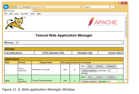
c. Tomcat web.xml
It is one of the main configuration files for the Tomcat server. It is located in the
TOMCAT_ROOT_DIR\conf folder. This configuration file is used for basic web
application’s configuration shared by all web applications that will be deployed on
the Tomcat server instance.
Below is the web.xml with no options:
<?xml version=”1.0” encoding=”ISO-8859-1”?>
<web-app xmlns=”http://xmlns.jcp.org/xml/ns/javaee”
xmlns:xsi=”http://www.w3.org/2001/XMLSchema-instance”
xsi:schemaLocation=”http://xmlns.jcp.org/xml/ns/javaee
http://xmlns.jcp.org/xml/ns/javaee/web-app_4_0.xsd”
version=”4.0”>
...
</web-app>
The above simplified web.xml contains <web-app> element which will contain
options for operating all web applications deployed in this Tomcat instance. The
<web-app> element represents the configuration options for a web application.
It is required that all deployment descriptors must confirm to XML schema for the
Servlet 4.0. Web-app is the root element for the deployment descriptor, web.xml file.
d. Tomcat context.xml
In Tomcat, the Context Container represents a single web application running within
a given instance of Tomcat. A web site is made up of one or more Contexts. For each
explicitly configured web application, there should be one context element either in
server.xml or in a separate context XML fragment file.
Here is an example of context.xml
<?xml version=”1.0” encoding=”UTF-8”?>
<!-- The contents of this file will be loaded for each web application -->
<Context>
<!-- Default set of monitored resources. If one of these changes, the -->
<!-- web application will be reloaded. -->
<WatchedResource>WEB-INF/web.xml</WatchedResource>
<WatchedResource>WEB-INF/tomcat-web.xml</WatchedResource>
<WatchedResource>${catalina.base}/conf/web.xml</WatchedResource>
<!-- Uncomment this to disable session persistence across Tomcat restarts -->
<!--
<Manager pathname=”” />
-->
</Context>
Application Activity 11.2.
Having Apache Tomcat server installed on your computer, do the following:
1. Change its connector port and set it to: 9999
2. Add a user with the following credentials:
a. Username: tomcat
b. Password: secret
c. Permission: Access to the "Server Status" page only
3. Put http://locatlhost:9999 in your browser and run it to make sure that it
is working.
4. What happens when you open the “Manage App” using the “tomcat”
and “secret” for username and password?
5. Where should you use the username and password indicated in
question 4?
11.3 Hypertext Transfer Protocol (HTTP) request / response
11.3.1. Http
Activity 11.3
Describe how web servers handle requests from different clients?
HTTP is an asymmetric request-response client-server protocol. An HTTP client
sends a request message to an HTTP server. The server, in turn, returns a response
message. In other words, HTTP is a pull protocol, the client pulls information from
the server (instead of server pushes information down to the client).
a. Key element of HTTP request
Below are the components of an http request:
• URL
• Form data
• HTTP method( if present)
• Cookies
• Uniform Resource Locator (URL)
It is a reference to a web resource that specifies its location on a computer network
and a mechanism for retrieving it.
Example: https://irembo.gov.rw/rolportal/web/rol/aboutus
• Form data
Data collected using HTML form is called form data and in HTTP request it is optional
information. If it is present then it will be present in header or body part of the HTTP
request depending on the HTTP method present in the request.
• HTTP method
It indicates desired action to be performed on dynamic web resources. HTTP has a
different method and in Servlet we implement that method based on action to be
performed.
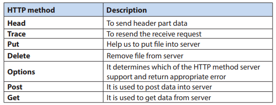
b. Key element of HTTP response
An HTTP response consist of the following:
* Status code
* Content type
* Actual content
* Cookies( if present)
• Status code
Status code represent status of HTTP request. It is a mandatory information and it
will be present in Header part of HTTP response.
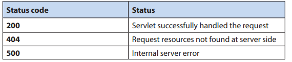
• Content Type
Content type tells the browser what type of content it is going to receive so that it
can prepare itself to handle response data. It is a mandatory information and it is
present in header part of HTTP request.
List of Content Type
Text/html
application/pdf
video/quicktime
image/jpeg
application/x-zip
11.3.2. Request-Response Process
This sections provides the logical breakdown of the HTTP request-response process.
After the client sends its request to a server, it is helpful to define a set of logical
steps which the server must perform before a response is sent.
The following steps are performed in the normal response process:
• Authorization translation
• Name translation
• Path checks
• Object type
• Respond to request
• Log the transaction
If at any time one of these steps fail, another step must be performed to handle the error and inform the client about what happened.
Application Activity 11.3
1. Explain the process of http request.
2. Explain the process of http response.
11.4 Web application
Activity 11.4
Explain the difference between a website and web application.
11.4.1. The definition of web application
A web application is a collection of servlets, html pages, classes, and other resources
that can be bundled and run on multiple containers from multiple vendors. Briefly,
a web application is a container that can hold any combination of the following list
of objects:
• Servlets
• Java Server Pages (JSPs)
• Utility classes - is a static class that perform small and repetitive operations
on a kind of instance (example of utils classes ArrayUtils or IOUtils from
Apache)
• Static documents, including HTML, images, JavaScript libraries, cascading
style sheets (CSS), and so on
• Client-side classes
• Meta-information describing the web application (Metadata is data that
describes other data.)
11.4.2. Servlet
A Java servlet is a platform-independent web application component that is hosted
in a servlet container. Servlets communicate with web clients using a request/
response model managed by a servlet container, such as Apache Tomcat.
11.4.3. Servlet context
The servlet context is an object that is created when the web-application is started
in a servlet container and destroyed when the web-application is undeployed or
stopped. The servlet context object usually contains initialization parameters in the
form of a web.xml document.
11.4.4. Servlet container
It is the component of a web server that interacts with Java servlets. The container
is responsible to manage the life-cycle of servlet. Web server hands the request to
web container in which servlet is deployed and not to Servlet itself. Then container
provides request and response to servlet. Tomcat is the example of Servlet container.
Servlet Container provides the following services:
• It manages the servlet life cycle.
• The resources like servlets, JSP pages and HTML files are managed by servlet
container.
• It appends session ID to the URL path to maintain session (Session means
a particular interval of time. The container uses session ID to identify the
particular user.)
• Provides security service.
• It loads a servlet class from network services, file systems like remote file
system and local file system.
Life Cycle of a Servlet
The life cycle of the servlet is as follows:
1. Servlet class is loaded.
2. Servlet instance is created.
3. init method is invoked.
4. service method is invoked.
5. destroy method is invoked.
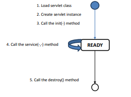
Figure 11. 7: Servlet life cycle
As displayed in the above diagram, there are three states of a servlet: new, ready
and end. The servlet is in new state if servlet instance is created. After invoking the
init() method, Servlet comes in the ready state. In the ready state, servlet performs
all the tasks. When the web container invokes the destroy() method, it shifts to the
end state.
11.4.5. Java server pages (JSP) files
Java Server Pages (JSP) is a technology for developing Webpages that supports
dynamic content. This helps developers insert java code in HTML pages by making
use of special JSP tags, most of which start with <% and end with %>. Using JSP,
you can collect input from users through Webpage forms, present records from a
database or another source, and create Webpages dynamically.
JSP tags can be used for a variety of purposes, such as retrieving information from a
database or registering user preferences, accessing JavaBeans components, passing
control between pages, and sharing information between requests, pages etc. A JSP
document must end with a .jsp extension.
The following code contains a simple example of a JSP file:
<HTML>
<BODY>
<% out.println(“MURAKAZA NEZA!”); %>
</BODY>
</HTML>
A JSP file is a server-generated web page. It contains Java code. The code is parsed
by the web server, which generates HTML that is sent to the user’s computer.
11.4.6. Configuration file
It is a file that contains configuration information for a particular web application.
When the application is executed, it consults the configuration file to see what
parameters are in effect
a. Deployment descriptor
A web application’s deployment descriptor describes the classes, resources and
configuration of the application and how the web server uses them to serve web
requests. When the web server receives a request for the application, it uses the
deployment descriptor to map the URL of the request to the code that ought to
handle the request.
The deployment descriptor is a file named web.xml. It resides in the app’s Web
application Archive (WAR) under the WEB-INF/ directory. The file is an XML file
whose root element is <web-app>.
The location of WEB-INF Directory

The root directory of you web application can have any name. In the above example
the root directory name is webapps.
The WEB-INF directory is located just below the web app root directory. This
directory is a meta information directory.
Here is a simple web.xml example that maps all URL paths (/*) to the servlet
class mysite.server.ComingSoonServlet:
<web-app xmlns=”http://java.sun.com/xml/ns/javaee” version=”2.5”>
<servlet>
<servlet-name>comingsoon</servlet-name>
<servlet-class>mysite.server.ComingSoonServlet</servlet-class>
</servlet>
<servlet-mapping>
<servlet-name>comingsoon</servlet-name>
<url-pattern>/*</url-pattern>
</servlet-mapping>
</web-app>
11.4.7. Manage Web Applications
In many production environments it is very useful to have the capability to manage
your web applications without having to shut down and restart Tomcat. The interface
is divided into six sections:
• Message - Displays success and failure messages.
• Manager - General manager operations like list and help.
• Applications - List of web applications and commands.
• Deploy - Deploying web applications.
• Diagnostics - Identifying potential problems.
• Server Information - Information about the Tomcat server.
a. Message
Displays information about the success or failure of the last web application manager
command you performed. If it succeeded OK is displayed and may be followed by a
success message. If it failed FAIL is displayed followed by an error message.

b. Manager
The Manager section has three links:
• List Applications - Redisplay a list of web applications.
• HTML Manager Help - A link to this document.
• Manager Help - A link to the comprehensive Manager App HOW TO.
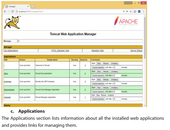
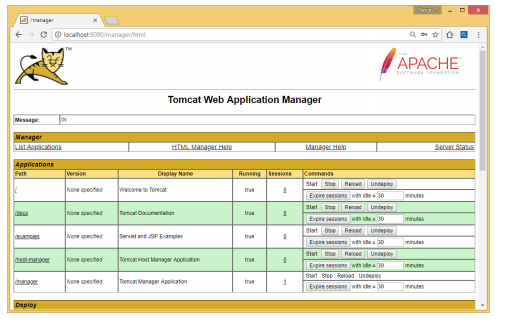
For each web application the following is displayed:
• Path - The web application context path.
• Display Name - The display name for the web application if it has one
configured in its “web.xml” file.
• Running - Whether the web application is running and available (true), or
not running and unavailable (false).
• Sessions - The number of active sessions for remote users of this web
application. The number of sessions is a link which when submitted displays
more details about session usage by the web application in the Message
box.
• Commands - Lists all commands which can be performed on the web
application. Only those commands which can be performed will be listed
as a link which can be submitted. No commands can be performed on the
manager web application itself. The following commands can be performed:
• Start - Start a web application which had been stopped.
• Stop - Stop a web application which is currently running and make it
unavailable.
• Reload - Reload the web application so that new “.jar” files in /WEB-INF/
lib/ or new classes in /WEB-INF/classes/ can be used.
• Undeploy - Stop and then remove this web application from the server.
Steps to open the Servlet and JSP examples
Step1: Click on /Examples in the path column
Step2: Click on Servlet examples


a. Deploy directory or WAR file located on server
Deploy and start a new web application, attached to the specified Context
Path: (which must not be in use by any other web application). This command is the
logical opposite of the Undeploy command.
• Deploy a Directory or WAR by URL
Install a web application directory or “.war” file located on the Tomcat server. If
no Context Path is specified, the directory name or the war file name without
the “.war” extension is used as the path. The WAR or Directory URL specifies a URL
(including the file: scheme) for either a directory or a web application archive (WAR)
file.
In this example the web application located in the directory C:\path\to\foo on the
Tomcat server (running on Windows) is deployed as the web application context
named /footoo.
Context Path: /footoo
WAR or Directory URL: file:C:/path/to/foo in our example it is C:\Program Files\
Apache Software Foundation\Tomcat 9.0\webapps\examples\jsp\include
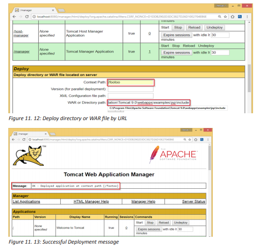
11.4.8. Using the documentation
Apache Tomcat has its built in documentation which will assist you in downloading
and installing Apache Tomcat, and using many of the Apache Tomcat features.
To explore this documentation, go to the Apache Tomcat home page and click on
documentation as shown in the figure below:
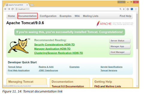
Application Activity 11.4
1. Why would you prefer to develop a web application?
2. Explain the functional difference between JSP and servlet?
3. Explain the servlet life cycle.
4. Write a JSP to display a message of welcome to your school.
11.5. A Uniform Resource Locator (URL)
Activity 11.5
Open your browser and enter the following website addresses:
http://www.reb.rw/index.php?id=270
Question: Compare the outputs and indicate the differences and resemblances.
11.5.1. Definition of URL
URL is the global address of documents and other resources on the World Wide Web.
Its main purpose is to identify the location of a document and other web resources
available on the Internet, and specify the mechanism for accessing it through a web
browser.
For instance, if you look at the address bar of your browser you will see:
http://www.reb.rw/index.php?id=270
11.5.2. The URL Syntax
The general syntax of URLs is the following: scheme://host:port/path?querystring#fragment-id
A URL has a linear structure and normally consists of some of the following:
• Scheme name — The scheme identifies the protocol to be used to access
the resource on the Internet. The scheme names followed by the three
characters :// (a colon and two slashes). The most commonly used protocols
are http://, https://, ftp://, and mailto://.
• Host name — The host name identifies the server where resource is located.
A hostname is a domain name assigned to a server computer. This is usually
a combination of the host’s local name with its parent domain’s name. For
example, http://www.reb.rw consists of host’s machine name www and the
domain name .reb.rw
• Port Number — Servers often deliver more than one type of service, so you
must also tell the server what service is being requested. These requests are
made by port number. Well-known port numbers for a service are normally
omitted from the URL. For example, web service HTTP is commonly
delivered on port 80.
• Path — The path identifies the specific resource within the host that the
user wants to access. For example, /html/html-url.php
• Query String — The query string contains data to be passed to server-side
scripts, running on the web server. For example, parameters for a search. The
query string preceded by a question mark, is usually a string of name and
value pairs separated by ampersands, for example, ?first_name=John&last_
name=Corner.
• Fragment identifier — The fragment identifier, if present, specifies a part or
a position within the overall resource or document. The fragment identifier
introduced by a hash mark “#” is the optional last part of a URL for a document.
When fragment identifier used with HTTP, it usually specifies a section or
location within the page, and the browser may scroll to display that part of
the page.
11.5.3. Static and dynamic web pages
a. Static
A static page is one that is usually designed in plain HTML and the content is always
same. A static website contains Web pages with fixed content. Each page is coded
in HTML and displays the same information to every visitor. Static sites are the most
basic type of website and are the easiest to create. A static site can be built by simply
creating a few HTML pages and publishing them to a Web server.
Advantages of static websites and web pages
• Easy to develop
• Cheap to develop
• Cheap to host
b. Dynamic
Dynamic webpages can show the different content or information based on the
results of a search or some other request. It is designed by server side scripting
language like PHP, ASP, JSP with HTML, CSS.
Advantages of dynamic websites and web pages
• Much more functional website
• Much easier to update
• Can connect with database
• New content brings people back to the site and helps in the search engines
• Can work as a system to allow staff or users to collaborate
Application Activity 11.5
1. Describe what you see on the URL given below: http://primature.gov.
rw/home.html?no_cache=1&tx_drblob_pi1%5BdownloadUid%5 D=484
2. Discuss the advantages of dynamic websites and web pages.
3. What are the barriers of static websites and webpages?
11.6. Project creation
Activity 11.6
You are requested to make a proposal of the website for your school,
1. Explain the process to create that website and test it on your computer.
2. Show the director of the school the cost of the website.
11.6.1. Project creation using Tomcat
Once you get Tomcat up and running on your server, the next step is configuring
its basic settings. If you plan to create a Web service that uses Apache Tomcat as its
server, it must be configured before you begin creating your Web service. Following
are the steps to configure the Tomcat Server:
Step 1:Configure Tomcat Server
The Tomcat configuration files are located in the “conf” sub-directory of your Tomcat
installed directory, e.g. “C:\Program Files\Apache Software Foundation\Tomcat 9.0\
conf”. There are 4 configuration XML files:
1. server.xml
2. web.xml
3. context.xml
4. tomcat-users.xml
Step 1(a) “conf\server.xml” - Set the TCP Port Number
1. Use a programming text editor (e.g., NotePad++, TextPad) to open the
configuration file “server.xml”, under the “conf” sub-directory of Tomcat
installed directory.

2. The default TCP port number configured in Tomcat is 8080, you may
choose any number between 1024 and 65535, which is not used by an
existing application. We shall choose 9999 in this example.
3. Locate the following lines (around Line 69) that define the HTTP
connector, and change port=”8080” to port=”9999”.
Notice: Remember to save changes
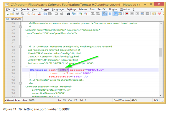
Step 1(b) “conf\web.xml” - Enabling Directory Listing
Directory listing is a web server function that displays a list of all the files when there
is not an index file, such as index.php and default.asp in a specific website directory.
Again, use a programming text editor to open the configuration file “web.xml”, under
the “conf” sub-directory of Tomcat installed directory.
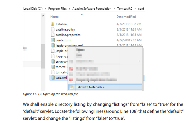
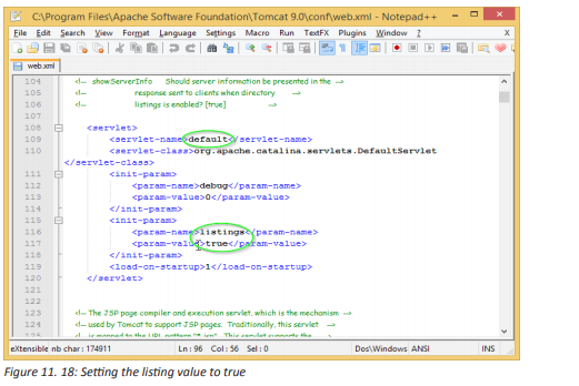
Step 1(c) “conf\context.xml” - Enabling Automatic Reload
We shall add the attribute reloadable=”true” to the <Context> element to enable
automatic reload after code changes. Again, this is handy for test system but not for
production, due to the overhead of detecting changes.
Locate the <Context> start element (around Line 19), and change it to <Context
reloadable=”true”>.
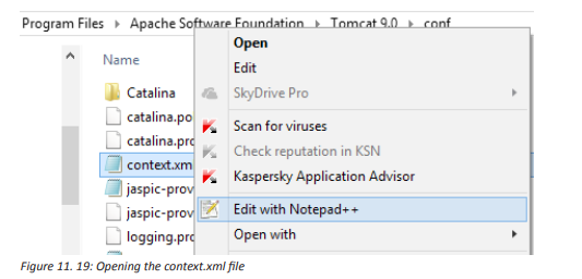
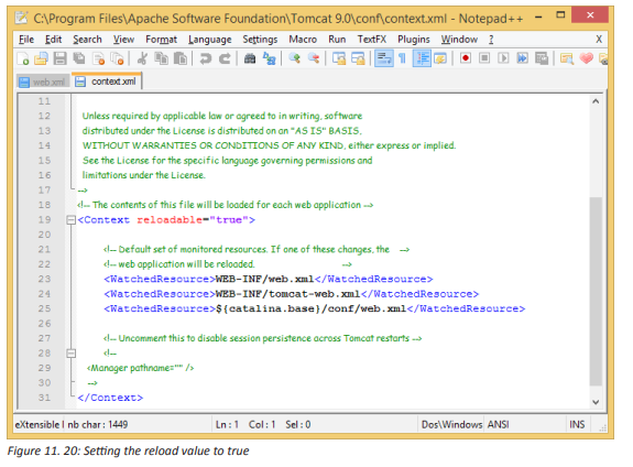
Step 2(a) Start Server
By default, Tomcat is set to start automatically when windows starts. But after
configuring Tomcat basic settings, the next step is to restart the server in order to
ensure that all configurations take effect. To do so, open the Tomcat configuration
properties, stop and start it as follows:
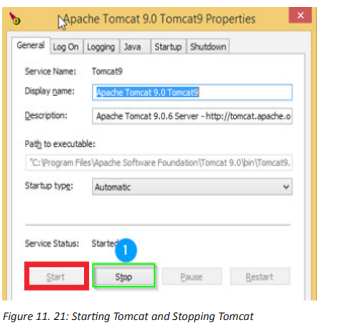
Step 2(b) Start a Client to Access the Server
Start a browser (Firefox, Chrome) as an HTTP client. Issue URL “http://localhost:9999”
to access the Tomcat server’s welcome page. The hostname “localhost” (with IP
address of 127.0.0.1) is meant for local loop-back testing inside the same machine.
Step 3: Develop and Deploy a WebApp
The container that holds the components of a web application is the directory
structure in which it exists. The first step in creating a web application is creating this
directory structure.
Step 3(a) Create the Directory Structure for your WebApp
The root directory of our web application should be placed under /webapps as
indicated in the figure below:
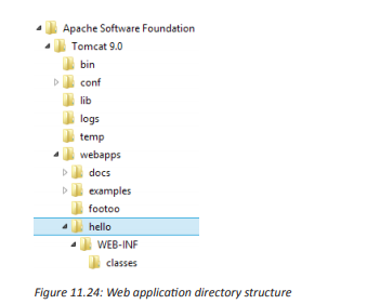
Let us call our first webapp “hello”. Go to Tomcat’s “webapps” sub-directory and
create the following directory structure for your webapp “hello” (as illustrated):
Under Tomcat’s “webapps”, create your webapp’s root directory “hello”
1. (i.e., “<TOMCAT_HOME>\webapps\hello”).
Under “hello”, create a sub-directory “WEB-INF”
2. (i.e., “<TOMCAT_HOME>\webapps\hello\WEB-INF”).
Under “WEB-INF”, create a sub-sub-directory “classes”
3. (i.e., “<TOMCAT_HOME>\webapps\hello\WEB-INF\classes”).
You need to keep your web resources (e.g., HTMLs, CSSs, images, scripts, servlets,
JSPs) in the proper directories:
• “hello”: This is called the context root (or document base directory) of your
webapp. You should keep all your HTML files and resources visible to the
web users (e.g., HTMLs, CSSs, images, scripts, JSPs) under this context root.
• “hello/WEB-INF”: This directory, although under the context root, is not
visible to the web users. This is where you keep your application’s web
descriptor file “web.xml”.
• “hello/WEB-INF/classes”: This is where you keep all the Java classes such as
servlet class-files.
You can issue the following URL to access the web application “hello”:
http://localhost:9999/hello
You should see the directory listing of the directory “<TOMCAT_HOME>\webapps\
hello”, which shall be empty at this point of time. (Take note that we have earlier
enabled directory listing in “web.xml”. Otherwise, you will get an error “404 Not
Found”).

Step 3(b) Write a Welcome Page
Create the following HTML page and save as “HelloHome.html” in your application’s
root directory “hello”.
1. <html>
2. <head><title>My Home Page</title></head>
3. <body>
4. <h1>My Name is MUGISHA. <br> This is my HOME.</h1>
5. </body>
6. </html>
You can browse this page by issuing this URL:
http://localhost:9999/hello/HelloHome.html
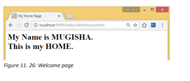
11.6.2. Steps to create web application project in Netbeans IDE
To create a servlet application in Netbeans IDE, you will need to follow the following
(simple) steps:
1. Open Netbeans IDE, Select File -> New Project

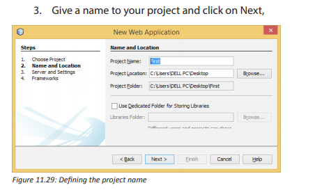
4. Click Finish
5. The complete directory structure required for the Servlet Application will
be created automatically by the IDE.

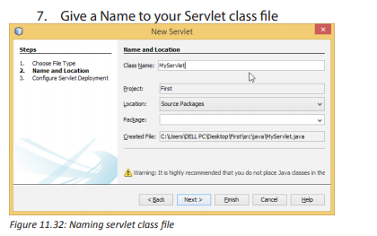
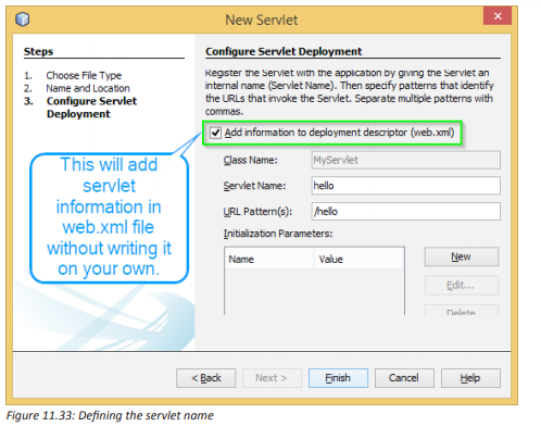

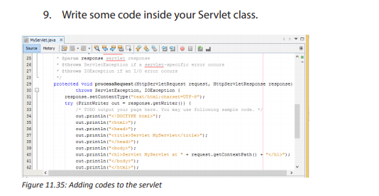
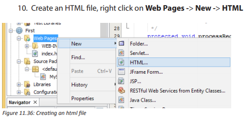

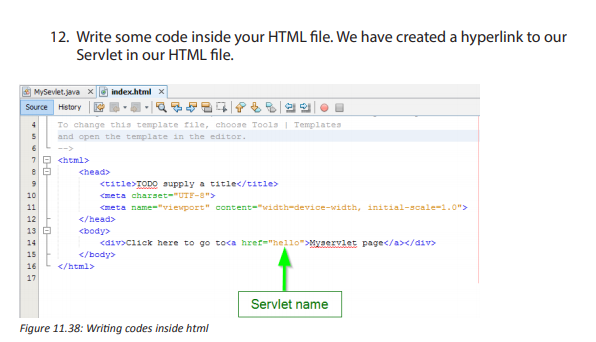

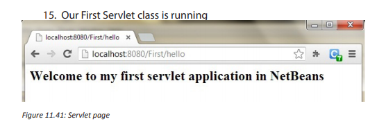
11.6.3. Http Session
Session is a conversional state between client and server and it can consists of
multiple request and response between client and server. This is how a HttpSession
object is created.
protected void doPost(HttpServletRequest req,
HttpServletResponse res)
throws ServletException, IOException {
HttpSession session = req.getSession();
}
a. .setAttribute()
You can store the user information into the session object by using setAttribute()
method and later when needed this information can be fetched from the session.
This is how you store info in session. Here we are storing username, emailid and
userage in session with the attribute name uName, uemailId and uAge respectively.
session.setAttribute(“uName”, “Mukamana”);
session.setAttribute(“uemailId”, “mukamana@gmail.com”);
session.setAttribute(“uAge”, “30”);
This First parameter is the attribute name and second is the attribute value. For e.g.
uName is the attribute name and Mukamana is the attribute value in the code above.
b. .getAttribute
To get the value from session we use the getAttribute() method of HttpSession
interface. Here we are fetching the attribute values using attribute names.
String userName = (String) session.getAttribute(“uName”);
String userEmailId = (String) session.getAttribute(“uemailId”);
String userAge = (String) session.getAttribute(“uAge”);
Session Example
index.html
<form action=”login”>
User Name:<input type=”text” name=”userName”/><br/>
Password:<input type=”password” name=”userPassword”/><br/>
<input type=”submit” value=”submit”/>
</form>
MyServlet1.java
import java.io.*;
import javax.servlet.*;
import javax.servlet.http.*;
public class MyServlet1 extends HttpServlet {
public void doGet(HttpServletRequest request, HttpServletResponse response){
try{
response.setContentType(“text/html”);
PrintWriter pwriter = response.getWriter();
String name = request.getParameter(“userName”);
String password = request.getParameter(“userPassword”);
pwriter.print(“Hello “+name);
pwriter.print(“Your Password is: “+password);
HttpSession session=request.getSession();
session.setAttribute(“uname”,name);
session.setAttribute(“upass”,password);
pwriter.print(“<a href=’welcome’>view details</a>”);
pwriter.close();
}catch(Exception exp){
System.out.println(exp);
}
}
}
MyServlet2.java
import java.io.*;
import javax.servlet.*;
import javax.servlet.http.*;
public class MyServlet2 extends HttpServlet {
public void doGet(HttpServletRequest request, HttpServletResponse response){
try{
response.setContentType(“text/html”);
PrintWriter pwriter = response.getWriter();
HttpSession session=request.getSession(false);
String myName=(String)session.getAttribute(“uname”);
String myPass=(String)session.getAttribute(“upass”);
pwriter.print(“Name: “+myName+” Pass: “+myPass);
pwriter.close();
}catch(Exception exp){
System.out.println(exp);
}
}
}
web.xml
<web-app>
<servlet>
<servlet-name>Servlet1</servlet-name>
<servlet-class>MyServlet1</servlet-class>
</servlet>
<servlet-mapping>
<servlet-name>Servlet1</servlet-name>
<url-pattern>/login</url-pattern>
</servlet-mapping>
<servlet>
<servlet-name>Servlet2</servlet-name>
<servlet-class>MyServlet2</servlet-class>
</servlet>
<servlet-mapping>
<servlet-name>Servlet2</servlet-name>
<url-pattern>/welcome</url-pattern>
</servlet-mapping>
</web-app>
The ouput will be as follows:

Application Activity 11.6
1. Create a web application project as follows:
• Location: Desktop/Senior6
• Title of the index page: Library
• Message: Welcome to the school library.
• Class Name: LibraryServlet
• Servlet Name: LibraryServlet
• Your servlet page should list some of the books
11. 7 Java Server Pages
Activity 11.7
Look at the codes indicated below and explain the difference between them.
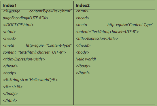
11.7.1 Introduction
Java Server Pages (JSP) is a standard Java extension that is defined on top of the
servlet Extensions. The goal of JSPs is the simplified creation and management of
dynamic Web pages. JSPs allow you to combine the HTML of a Web page with pieces
of Java code in the same document. The Java code is surrounded by special tags that
tell the JSP container that it should use the code to generate a servlet, or part of one.
The benefit of JSPs is that you can maintain a single document that represents both
the page and the Java code that enables it. The JSP tags begin and end with angle
brackets, just like HTML tags, but the tags also include percent signs, so all JSP tags
are denoted by <% JSP code here %>
11.7.1 Creating a new JSP page in netbeans
To create a JSP page, the following steps are necessary:
1. Right click on your project’s name ->New -> JSP(in this example, the
project is “Senior6”)
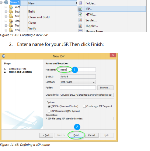
3. Netbeans creates a skeleton JSP page comprising of little more than the
<head> and <body> tags and a couple of commented-out sample bean
directives.
4. Add codes as follows:

11.7.3. JSP directives
Directives are messages to the JSP container and are denoted by the “@”:
<%@ directive {attr=”value”}* %>
Directives do not send anything to the out stream, but they are important in setting
up your JSP page’s attributes and dependencies with the JSP container. For example,
the line:
<%@ page language=”java” %> says that the scripting language being used within
the JSP page is Java.
The most important directive is the page directive. It defines a number of page
dependent attributes and communicates these attributes to the JSP container.
These attributes include: language, extends, import, session, buffer, autoFlush,
isThreadSafe, info and errorPage. For example:
<%@ page session=”true” import=”java.util.*” %>
This line first indicates that the page requires participation in an HTTP session. The
import attribute describes the types that are available to the scripting environment.
11.7.4. JSP scripting elements
Once the directives have been used to set up the scripting environment you can
utilize the scripting language elements. JSP has three scripting language elements—
declarations, scriptlets, and expressions. A declaration will declare elements,
a scriptlet is a statement fragment, and an expression is a complete language
expression. In JSP each scripting element begins with a “<%”. The syntax for each is:
<%! declaration %>
<% scriptlet %>
<%= expression %>
White space is optional after “<%!”, “<%”, “<%=”, and before “%>.”
All these tags are based upon XML; you could even say that a JSP page can be
mapped to a XML document. The XML equivalent syntax for the scripting elements
above would be:
<jsp:declaration> declaration </jsp:declaration>
<jsp:scriptlet> scriptlet </jsp:scriptlet>
<jsp:expression> expression </jsp:expression>
In addition, there are two types of comments:
<%-- jsp comment --%>
<!-- html comment -->
The first form allows you to add comments to JSP source pages that will not appear
in any form in the HTML that is sent to the client. Of course, the second form of
comment is not specific to JSPs, it’s just an ordinary HTML comment.
a. Declaration
Declarations are used to declare variables and methods in the scripting language
used in a JSP page. The declaration must be a complete Java statement and
cannot produce any output in the out stream. In the Hello.jsp example below, the
declarations for the variables loadTime, loadDate and hitCount are all complete
Java statements that declare and initialize new variables.
<%@page contentType=”text/html” pageEncoding=”UTF-8”%>
<!DOCTYPE html>
<%-- This JSP comment will not appear in the
generated html --%>
<%-- This is a JSP directive: --%>
<%@ page import=”java.util.*” %>
<%-- These are declarations: --%>
<%!
long loadTime= System.currentTimeMillis();
Date loadDate = new Date();
int hitCount = 0;
%>
<html><body>
<%-- The next several lines are the result of a
JSP expression inserted in the generated html;
the ‘=’ indicates a JSP expression --%>
<H1>This page was loaded on <%= loadDate %></H1>
<H1>Hello, world! It’s <%= new Date() %></H1>
<H2>Here’s an object: <%= new Object() %></H2>
<H2>This page has been up
<%= (System.currentTimeMillis()-loadTime)/1000 %>
seconds</H2>
<H3>Page has been accessed <%= ++hitCount %>
times since <%= loadDate %></H3>
<%-- A “scriptlet” that writes to the server
console and to the client page.
Note that the ‘;’ is required: --%>
<%
System.out.println(“Goodbye”);
out.println(“<h1>Murabeho!</h1>”);
%>
</body></html>
When you run this program you will see that the variables loadTime, loadDate and
hitCount hold their values between hits to the page, so they are clearly fields and
not local variables. At the end of the example is a scriptlet that writes “Goodbye” to
the Web server console and “Murabeho” to the implicit JspWriter object out.
b. Scriptlets
Scriplets are used to insert Java code in your JSP page. The Java code is enclosed
within tags <% %>, which are known as Scriplet Tags. A JSP Scriplet tag may hold
the Java code comprising java expressions, statements or variable. JSP comes with a
built-in Java object named out which allows us to write a text to the JSP web page,
below is an example of how we can use the in-built out object within the scriplet tag
to display a message on a web page.
<%@page contentType=”text/html” pageEncoding=”UTF-8”%>
<!DOCTYPE html>
<html>
<head>
<meta http-equiv=”Content-Type” content=”text/html; charset=UTF-8”>
<title>First JSP</title>
</head>
<body>
<% out.println(“Saying hello from Java using Scriplet Tag”); %>
</body>
</html>
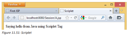
c. Expressions
Expression tag evaluates the expression placed in it, converts the result into String
and send the result back to the client through response object. Java expressions
result in a value, hence JSP Expression tags are used to enclose java expressions that
yield a value to be printed on a JSP web page. The Java expressions are enclosed in
within <%= %> tags.
JSP expression tag Examples
<%@page contentType=”text/html” pageEncoding=”UTF-8”%>
<!DOCTYPE html>
<html>
<head>
<meta http-equiv=”Content-Type” content=”text/html; charset=UTF-8”>
<title>Expression</title>
</head>
<body>
<% String str = “Hello world”; %>
<%= str %>
</body>
</html>
Executing this JSP prints the value of java expression str which yields a value of
String object.
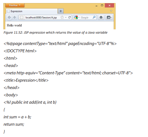
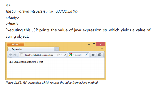
11.7.5. JSP page attributes and scope
By poking around in the HTML documentation for servlets and JSPs, you will find
features that report information about the servlet or JSP that is currently running.
The following example displays a few of these pieces of data.
//:! c15:jsp:PageContext.jsp
<%--Viewing the attributes in the pageContext--%>
<%-- Note that you can include any amount of code
inside the scriptlet tags --%>
<%@ page import=”java.util.*” %>
<html><body>
Servlet Name: <%= config.getServletName() %><br>
Servlet container supports servlet version:
<% out.print(application.getMajorVersion() + “.”
+ application.getMinorVersion()); %><br>
<%
session.setAttribute(“My country”, “Rwanda”);
for(int scope = 1; scope <= 4; scope++) { %>
<H3>Scope: <%= scope %></H3>
<% Enumeration e =
pageContext.getAttributeNamesInScope(scope);
while(e.hasMoreElements()) {
out.println(“\t<li>” +
e.nextElement() + “</li>”);
}
}
%>
</body></html>
///:~
This example also shows the use of both embedded HTML and writing to out in
order to output to the resulting HTML page.
The first piece of information produced is the name of the servlet, which will probably
just be “JSP” but it depends on your implementation. You can also discover the
current version of the servlet container by using the application object. Finally, after
setting a session attribute, the “attribute names” in a particular scope are displayed.
You don’t use the scopes very much in most JSP programming; they were just shown
here to add interest to the example. There are four attribute scopes, as follows: The
page scope (scope 1), the request scope (scope 2), the session scope (scope 3). Here, the
only element available in session scope is “My country,” added right before the for
loop), and the application scope (scope 4), based upon the Servlet Context object.
Application Activity 11.7
1. Why could you use JSP instead of Servlets?
2. How is JSP combined with HTML?
3. Create a JSP web form with the following characteristics:
a. The form should contain input boxes to receive student’s names and
the year of study.
b. A command button to submit recorded information
c. When the “submit” button is clicked, the form will display a message
as follows: Hello “student’s names”, you study in “year of study”
11.8 tandard Tag Library (JSTL)
Activity 11.7
1. Explain how paired and unpaired tags are used?
2. Provide an example for each one of the following types of tags:
a. Formatting tags
b. Page Structure tags
c. Control tags
11.8.1. Introduction
The JavaServer Pages Standard Tag Library (JSTL) is a collection of useful JSP tags
which encapsulates the core functionality common to many JSP applications.
JSTL has support for common, structural tasks such as iteration and conditionals,
tags for manipulating XML documents, internationalization tags, and SQL tags. It
also provides a framework for integrating the existing custom tags with the JSTL
tags.
To use any of the libraries, you must include a <taglib> directive at the top of each
JSP that uses the library.
11.8.2. Classification of the JSTL Tags
The JSTL tags can be classified, according to their functions, into the following JSTL
tag library groups that can be used when creating a JSP page:
• Core Tags
• Formatting tags
• SQL tags
• XML tags
• JSTL Functions
a. Core Tags
The core group of tags are the most commonly used JSTL tags. Following is the
syntax to include the JSTL Core library in your JSP −
<%@ taglib prefix = “c” uri = “http://java.sun.com/jsp/jstl/core” %>
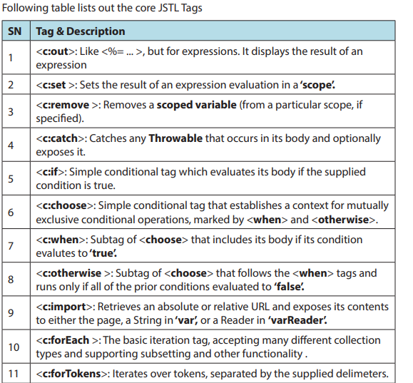
Below is a simple example of tag:
<%@ taglib uri=”http://java.sun.com/jsp/jstl/core” prefix=”c” %>
<html>
<head>
<title>Core Tag Example</title>
</head>
<body>
<c:forEach var=”j” begin=”1” end=”3”>
Item <c:out value=”${j}”/><p>
</c:forEach>
</body>
</html>
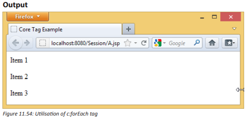
b. Formatting Tags
The JSTL formatting tags are used to format and display text, the date, the time,
and numbers for internationalized Websites. Following is the syntax to include
formatting library in your JSP.
<%@ taglib prefix = “fmt” uri = “http://java.sun.com/jsp/jstl/fmt” %>
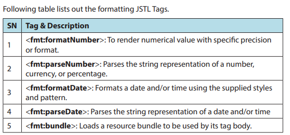
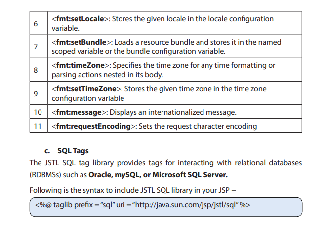
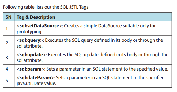


e. JSTL Functions
JSTL includes a number of standard functions, most of which are common string
manipulation functions. Following is the syntax to include JSTL Functions library in your JSP −
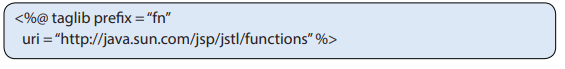

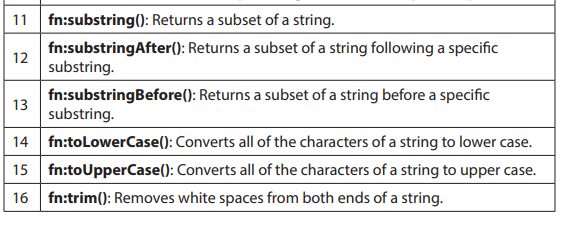
Application Activity 11.7
Identify and explain different tags found in the codes below:
<%@ page language="java" contentType="text/html; charset=US-ASCII"
pageEncoding="US-ASCII"%>
<!DOCTYPE html PUBLIC "-//W3C//DTD HTML 4.01 Transitional//EN" "http://www.w3.org/TR/
html4/loose.dtd">
<html>
<head>
<meta http-equiv="Content-Type" content="text/html; charset=US-ASCII">
<title>Home Page</title>
<%@ taglib uri="http://java.sun.com/jsp/jstl/core" prefix="c" %>
<style>
table,th,td
{
border:1px solid black;
}
</style>
</head>
<body>
<%-- Using JSTL forEach and out to loop a list and display items in table --%>
<table>
<tbody>
<tr><th>ID</th><th>Name</th><th>Role</th></tr>
<c:forEach items="${requestScope.empList}" var="emp">
<tr><td><c:out value="${emp.id}"></c:out></td>
<td><c:out value="${emp.name}"></c:out></td>
<td><c:out value="${emp.role}"></c:out></td></tr>
</c:forEach>
</tbody>
</table>
<br><br>
<%-- simple c:if and c:out example with HTML escaping --%>
<c:if test="${requestScope.htmlTagData ne null }">
<c:out value="${requestScope.htmlTagData}" escapeXml="true"></c:out>
</c:if>
<br><br>
<%-- c:set example to set variable value --%>
<c:set var="id" value="5" scope="request"></c:set>
<c:out value="${requestScope.id }" ></c:out>
<br><br>
<%-- c:catch example --%>
<c:catch var ="exception">
<% int x = 5/0;%>
</c:catch>
<c:if test = "${exception ne null}">
<p>Exception is : ${exception} <br>
Exception Message: ${exception.message}</p>
</c:if>
<br><br>
<%-- c:url example --%>
<a href="<c:url value="${requestScope.url }"></c:url>">JournalDev</a>
</body>
</html>
11.9 Java Database Connectivity (JDBC) connection
Activity 11.7
1. Illustrate how websites communicate with databases?
2. What are the benefits of having a website which is connected to a
database?
JDBC is a standard Java application programming interfaces (APIs) for databaseindependent connectivity between the Java programming language and a wide
range of databases.
The JDBC library includes APIs for each of the tasks mentioned below that are
commonly associated with database usage.
• Making a connection to a database.
• Creating SQL or MySQL statements.
• Executing SQL or MySQL queries in the database.
• Viewing & Modifying the resulting records.
Fundamentally, JDBC is a specification that provides a complete set of interfaces
that allows for portable access to an underlying database.
11.9.1. Common JDBC Components
The JDBC API provides the following interfaces and classes:
• Driver Manager: This class manages a list of database drivers. Matches
connection requests from the java application with the proper database
driver using communication sub protocol. The first driver that recognizes
a certain subprotocol under JDBC will be used to establish a database
Connection.
• Driver: This interface handles the communications with the database server.
You will interact directly with Driver objects very rarely. Instead, you use
DriverManager objects, which manages objects of this type. It also abstracts
the details associated with working with Driver objects.
• Connection: This interface with all methods for contacting a database.
The connection object represents communication context, i.e., all
communication with database is through connection object only.
• Statement: You use objects created from this interface to submit the SQL
statements to the database. Some derived interfaces accept parameters in
addition to executing stored procedures.
• ResultSet: These objects hold data retrieved from a database after you
execute an SQL query using Statement objects. It acts as an iterator to allow
you to move through its data.
• SQLException: This class handles any errors that occur in a database
application.
11.9.2. Load Driver
1. Download MySQL Connector/J, name ‘mysql-connector-java-5.1.46.zip’
from the Official Site at https://dev.mysql.com/downloads/connector/j
Extract the zip file to a folder, you will see file ‘mysql-connector-java-5.1.46-
bin.jar’ which is the library file that we want. Just copy the file to the library
folder, for example to “C:\Program Files\Java\jdk1.6.0_02\lib” directory.
2. Start Netbeans and create a new project (File->New Project; a window
will appear. Select Java from the Categories list and Java Application from
the Projects list. Click Next. In the New Java Application window, enter the
name and location of the project.)
3. Add JDBC Driver to the “First” project on NetBeans (Add a library).
a. In Projects window, right click the project name and select Properties.
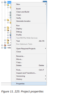

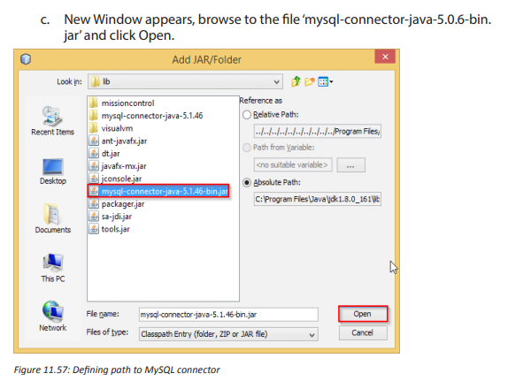

Note: You should keep mysql-connector-java-5.1.46-bin.jar in the directory that
you won’t delete it (ex. not in temp folder). May be in the same directory that keep
common library files. If you delete the file without delete a link from the project, the
project will show error about missing library.
11.9.3. Connecting to the database
Supposing we have a table named books in a MySQL database called ebooks with
the following fields:
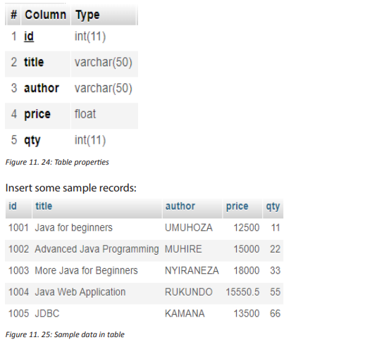
a. Writing code to connect to the database
Use the <sql:setDataSource> tag to create a data source to our database like this:
<sql:setDataSource
var=”myDB”
driver=”com.mysql.jdbc.Driver”
url=”jdbc:mysql://localhost:3306/ebooks”
user=”root”password=”secret”
/>
Remember to change the user and password attributes according to your MySQL
settings. Note that the data source is assigned to a variable called my DB for reference
later.
b. Writing code to query the records
Use the <sql:query> tag to create a query to the database as follows:
<sql:queryvar=”list_users”dataSource=”${myDB}”>
SELECT * FROM books;
</sql:query>
Note that the dataSource attribute refers to the data source myDB created in the
previous step, and result of this query is assigned to a variable called listUsers for
reference later.
c. Writing code to display the records
Use the <c:forEach> tag to iterate over the records returned by the <sql:query> tag.
And for each record, use the <c:out> tag to print value of a column in the table, like
this:
<c:forEach var=”books” items=”${books.rows}”>
<td><c:out value=”${books.id}” /></td>
<td><c:out value=”${books.title}” /></td>
<td><c:out value=”${books.author}” /></td>
<td><c:out value=”${books.price}” /></td>
<td><c:out value=”${books.qty}” /></td>
</c:forEach>
Note that the items attribute of the <c:forEach> tag refers to the listUsers variable
assigned by the <sql:query> tag.
d. The complete JSP code
Now we wire the above pieces together to form a complete JSP page with taglib
directives to import JSTL tags and HTML code to display the books list in tabular
format. Code of the complete JSP page is as follows (books.jsp):
<%@ taglib uri=”http://java.sun.com/jsp/jstl/core” prefix=”c” %>
<%@ taglib uri=”http://java.sun.com/jsp/jstl/sql” prefix=”sql” %>
<%@page contentType=”text/html” pageEncoding=”UTF-8”%>
<!DOCTYPE html>
<html>
<head>
<meta http-equiv=”Content-Type” content=”text/html; charset=UTF-8”>
<title>JSP List books</title>
</head>
<body>
<sql:setDataSource
var=”myDB”
driver=”com.mysql.jdbc.Driver”
url=”jdbc:mysql://localhost:3306/ebooks”
user=”root” password=””
/>
<sql:query var=”books” dataSource=”${myDB}”>
SELECT * FROM books;
</sql:query>
<div align=”center”>
<table border=”1” cellpadding=”5”>
<caption><h2>List of books</h2></caption>
<tr>
<th>ID</th>
<th>Title</th>
<th>Author</th>
<th>Price</th>
<th>Quantity</th>
</tr>
<c:forEach var=”books” items=”${books.rows}”>
<tr>
<td><c:out value=”${books.id}” /></td>
<td><c:out value=”${books.title}” /></td>
<td><c:out value=”${books.author}” /></td>
<td><c:out value=”${books.price}” /></td>
<td><c:out value=”${books.qty}” /></td>
</tr>
</c:forEach>
</table>
</div>
</body>
</html>
e. Testing the application
Supposing we put the books.jsp file inside the web application called First on
localhost Tomcat, type the following URL to run the list books JSP page:
http://localhost:8080/First/books.jsp
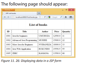
11.9.4. Inserting data into tables
We need 2 files to insert a new book record in the books table created in the previous
section in MySQL:
• index.html: for getting the values from the user
• addbooks.jsp: A JSP file that process the request
Codes for index.html are as follows:
<!DOCTYPE html>
<html>
<body>
<form method=”post” action=”addbook.jsp”>
ID:
<input type=”text” name=”id”>
<br><br>
Title:
<input type=”text” name=”title”>
<br><br>
Author:
<input type=”text” name=”author”>
<br><br>
Price: <input type=”text” name=”price”>
<br><br>
Quantity:
<input type=”text” name=”qty”>
<br><br>
<input type=”submit” value=”submit”>
</form>
</body>
</html>
Codes for addbooks.jsp are as follows:
<%@ page language=”java” contentType=”text/html; charset=ISO-8859-1”
pageEncoding=”ISO-8859-1”%>
<%@page import=”java.sql.*,java.util.*”%>
<%@ taglib uri=”http://java.sun.com/jsp/jstl/core” prefix=”c” %>
<%@ taglib uri=”http://java.sun.com/jsp/jstl/sql” prefix=”sql” %>
<%
String id=request.getParameter(“id”);
String title=request.getParameter(“title”);
String author=request.getParameter(“author”);
String price=request.getParameter(“price”);
String qty=request.getParameter(“qty”);
try
{
Class.forName(“com.mysql.jdbc.Driver”);
Connection conn = DriverManager.getConnection(“jdbc:mysql://localhost:3306/ebooks”, “root”,
“”);
Statement st=conn.createStatement();
int i=st.executeUpdate(“insert into books(id,title,author,price, qty)
values(‘”+id+”’,’”+title+”’,’”+author+”’,’”+price+”’,’”+qty+”’)”);
out.println(“Data is successfully inserted!”);
}
catch(Exception e)
{
System.out.print(e);
e.printStackTrace();
}
%>
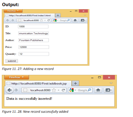
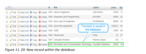
11.9.5. Updating tables
To update data into books table created in the previous section, we need 3 files:
• index.jsp: To retrieve data from database with an update option.
• update.jsp: Show the book data as per the selected id of book (Suppose
you select book id 1001, then it show only the information of id 1001).
• update-process.jsp: Process the user data after edit.
index.jsp:
<%@page contentType=”text/html” pageEncoding=”UTF-8”%>
<!DOCTYPE html>
<%@ page import=”java.sql.*” %>
<%@ page import=”java.io.*” %>
<%@page import=”java.sql.DriverManager”%>
<%@page import=”java.sql.ResultSet”%>
<%@page import=”java.sql.Statement”%>
<%@page import=”java.sql.Connection”%>
<%
String id = request.getParameter(“id”);
String driver = “com.mysql.jdbc.Driver”;
String connectionUrl = “jdbc:mysql://localhost:3306/”;
String database = “ebooks”;
String userid = “root”;
String password = “”;
try {
Class.forName(driver);
} catch (ClassNotFoundException e) {
e.printStackTrace();
}
Connection connection = null;
Statement statement = null;
ResultSet resultSet = null;
%>
<html>
<body>
<h1>Retrieve data from database in jsp</h1>
<table border=”1”>
<tr>
<td>id</td>
<td>Title</td>
<td>Author</td>
<td>Price</td>
<td>Quantity</td>
<td>update</td>
</tr>
<%
try{
connection = DriverManager.getConnection(connectionUrl+database, userid, password);
statement=connection.createStatement();
String sql =”select * from books”;
resultSet = statement.executeQuery(sql);
while(resultSet.next()){
%>
<tr>
<td><%=resultSet.getString(“id”) %></td>
<td><%=resultSet.getString(“title”) %></td>
<td><%=resultSet.getString(“author”) %></td>
<td><%=resultSet.getString(“price”) %></td>
<td><%=resultSet.getString(“qty”) %></td>
<td><a href=”update.jsp?id=<%=resultSet.getString(“id”)%>”>update</a></td>
</tr>
<%
}
connection.close();
} catch (Exception e) {
e.printStackTrace();
}
%>
</table>
</body>
</html>

update.jsp:
<%@page contentType=”text/html” pageEncoding=”UTF-8”%>
<!DOCTYPE html>
<%@page import=”java.sql.DriverManager”%>
<%@page import=”java.sql.ResultSet”%>
<%@page import=”java.sql.Statement”%>
<%@page import=”java.sql.Connection”%>
<%
String id = request.getParameter(“id”);
String driver = “com.mysql.jdbc.Driver”;
String connectionUrl = “jdbc:mysql://localhost:3306/”;
String database = “ebooks”;
String userid = “root”;
String password = “”;
try {
Class.forName(driver);
} catch (ClassNotFoundException e) {
e.printStackTrace();
}
Connection connection = null;
Statement statement = null;
ResultSet resultSet = null;
%>
<%
try{
connection = DriverManager.getConnection(connectionUrl+database, userid, password);
statement=connection.createStatement();
String sql =”select * from books where id=”+id;
resultSet = statement.executeQuery(sql);
while(resultSet.next()){
%>
<!DOCTYPE html>
<html>
<body>
<h1>Update data from database in jsp</h1>
<form method=”post” action=”update-process.jsp”>
<input type=”hidden” name=”id” value=”<%=resultSet.getString(“id”) %>”>
<input type=”text” name=”id” value=”<%=resultSet.getString(“id”) %>”>
<br>
ID:<br>
<input type=”text” name=”id” value=”<%=resultSet.getString(“id”) %>”>
<br>
Title:<br>
<input type=”text” name=”title” value=”<%=resultSet.getString(“title”) %>”>
<br>
Author:<br>
<input type=”text” name=”author” value=”<%=resultSet.getString(“author”) %>”>
<br>
Price:<br>
<input type=”text” name=”price” value=”<%=resultSet.getString(“price”) %>”>
<br>
Quantity:<br>
<input type=”text” name=”qty” value=”<%=resultSet.getString(“qty”) %>”>
<br><br>
<input type=”submit” value=”Update”>
</form>
<%
}
connection.close();
} catch (Exception e) {
e.printStackTrace();
}
%>
</body>
</html>
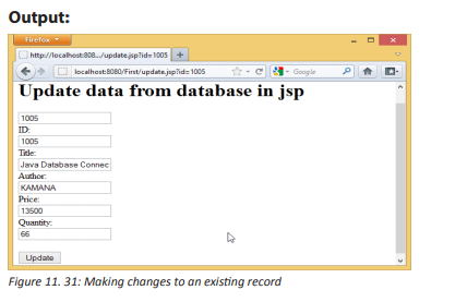
update-process.jsp
<%@page contentType=”text/html” pageEncoding=”UTF-8”%>
<!DOCTYPE html>
<%@ page import=”java.sql.*” %>
<%! String driverName = “com.mysql.jdbc.Driver”;%>
<%!String url = “jdbc:mysql://localhost:3306/ebooks”;%>
<%!String user = “root”;%>
<%!String psw = “”;%>
<%
String id = request.getParameter(“id”);
String title=request.getParameter(“title”);
String author=request.getParameter(“author”);
String price=request.getParameter(“price”);
String qty=request.getParameter(“qty”);
if(id != null)
{
Connection con = null;
PreparedStatement ps = null;
int personID = Integer.parseInt(id);
try
{
Class.forName(driverName);
con = DriverManager.getConnection(url,user,psw);
String sql=”Update books set id=?,title=?,author=?,price=?,qty=? where id=”+id;
ps = con.prepareStatement(sql);
ps.setString(1,id);
ps.setString(2, title);
ps.setString(3, author);
ps.setString(4, price);
ps.setString(5, qty);
int i = ps.executeUpdate();
if(i > 0)
{
out.print(“Record Updated Successfully”);
}
else
{
out.print(“There is a problem in updating Record.”);
}
}
catch(SQLException sql)
{
request.setAttribute(“error”, sql);
out.println(sql);
}}
%>
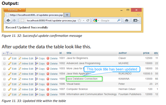
Application Activity 11.9
Develop a web application that connects to a database. You could use MySql
database. The program could collect data from the user (via a form) and store it
in a database table.
End unit assessment
1. How can you change the connector port while configuring Apache
Tomcat?
2. How does the servlet container interact with java servlet?
3. How could you access and run Tomcat Servlet and JSP examples?
4. Develop a web application so that it stores information in a session
variable. Use the session variable in the JSP output page.
UNIT 12: INTRODUCTION TO COMPUTER GRAPHICS
Introductory Activity
Observe the picture below and answer the following questions:
1. Describe what you see.
2. Describe how the pictures inside are arranged.Are these pictures
created using the same material?
3. How can you measure the size of each picture?
4. Is it easy to modify these pictures? Explain.
5. Explain the areas where pictures are used.
6. Why is it important to have good pictures in business advertisement?
7. Nowadays, youth like posting their nakedness pictures on social media.
Discuss the inconvenience.

12.1 Definition of Computer graphics terms
Activity 12.1
By using different mobile phones, take pictures of the same group of students in
your classroom. After saving those pictures in one folder and observing carefully,
give the difference between them. Explain what could be the cause of that
difference.
12.1.1 Introduction
The human perception of the world is done through the five senses among which
the view is very important. Our brain recognizes the faces of people and the shapes
of things because they retain their pictures.
Currently, the use of computers has helped to digitalise the images and the work
of drawing became easier than before. Consequently, a new area of application
of computer science called computer graphics was born and hence pictures and
images are used in different areas of the human life for its development. Computer
Graphics involves the ways in which images can be displayed, manipulated and
stored using a computer. Computer graphics provides the software and hardware
techniques or methods for generating images.
12.1.2.Definition of different terms
Computer graphics can be defined in two ways depending on the circumstances:
Computer Graphics is an art of drawing pictures, lines, charts, etc, using computers
with the help of programming. Computer graphics are made up of number of pixels.
A pixel is the smallest graphical picture or unit represented on the computer screen.
or
Computer graphics are pictures and films created by using computers. Usually, the
term refers to computer-generated image data created with help from specialized
graphical hardware and software.
Computer graphics can be classified into two categories: Raster or Bitmap graphics
and Vector or Object-oriented graphics.
1. Raster (Bitmap) Graphics
These are pixel based graphics and the pixels can be modified individually.
• The images are easy to edit in memory and display on TV monitors owing to
the arrangement of the pixels in a rectangular array.
• The image size is determined on the basis of image resolution.
• These images cannot be scaled easily; resizing do not work very well and
can significantly distort the image.
• Bitmap graphics are used for general purpose images and in particular
photographs.
2. Vector (Object-oriented) Graphics
These graphics are mathematically based images.
• Vector based images have smooth edges and therefore used to store images
composed of lines, circles and polygons.
• These images can easily be re-scaled and rotated.
• They can not easily accommodate complex images such as photographs
where colour information varies from pixel to pixel.
• Vector graphics are well suited for graphs, e.g. in spreadsheets and for
scalable fonts, e.g. postscript fonts
3. A model of an object is a physical representation that shows what it
looks like or how it works. The model is often smaller than the object it
represents
4. The computer resolution is the number of pixels (individual points of
color) contained on a display monitor, expressed in terms of the number
of pixels on the horizontal axis and the number on the vertical axis.
5. A pixel is the smallest element of a picture that can be represented on
the screen of a device like a computer. Pixels per inch (PPI) or pixels per
centimeter (PPCM) are measurements of the pixel density (resolution)
of an electronic image device, such as a computer monitor or television
display, or image digitizing device such as a camera or image scanner.
6. 2D (2Dimensional) images are objects that are rendered visually on
paper, film or on screen in two planes representing width and height (X
and Y). Two-dimensional structures are also used in the construction of 3D
objects.

7. 3D computer graphics or three-dimensional computer graphics,
(in contrast to 2D computer graphics) are graphics that use a threedimensional representation of geometric data (often Cartesian) that is
stored in the computer for the purposes of performing calculations and
rendering 2D image.

8. A color scheme is the choice of colors used in design for a range of media.
For example, the use of a white background with black text is an example
of a basic and commonly default color scheme in writing.
9. 8-bit color graphics is a method of storing image information in a
computer’s memory or in an image file, such that each pixel is represented
by one (8-bit) byte. The maximum number of colors that can be displayed
at any one time is 28=256.
10. 16-bit color graphics also called High color is a method of storing
image information in a computer’s memory or in an image file where
computerand monitors can display as many as 216=65,536 colors,
which is adequate for most uses. Each pixel is represented by two
bytes i.e 16 bits, but some devices also support 15-bit high color.
However, graphic intensive video games and higher resolution video can
benefit from and take advantage of the higher color depths.
11. 32-bit color graphics is a method of storing image information in a
computer’s memory or in an image file where computer and monitors can
display as many as 232=4,294,967,296 colors, which is adequate for most
uses. Each pixel is represented by four (4) bytes i.e 32 bits.
a. Image compression
Image compression is minimizing the size in bytes of a graphic file without degrading
the quality of the image to an unacceptable level. The reduction in file size allows
more images to be stored in a given amount of disk or memory space. It also reduces
the time required for images to be sent over the Internet or downloaded from web
pages. Know an image’s file size and dimensions before or after uploading it into the
Library
b. Determination of an image’s file size and dimensions
The determination of an image’s file size and dimensions differs according to the
Operating System being used.
On MS Windows computers, Open the image in Windows Explorer to check
dimensions and file size by clicking the Windows Start button on the taskbar. After
opening the folder containing the image, right clicking the icon of the image file,
and in the pop up menu, click on property and details. The result will look like below.
The wanted information are circled with red line

c. Calculating size of an uncompressed image file
byte is a unit of storage in computing, and unfortunately, a byte isn’t big enough
to hold a pixel’s worth of information. It actually takes 2 to 3 bytes to store one pixel
of a color image.
So the pixels in the image store a color at a given point in the image, but it takes 2
to 3 bytes of storage to record this value. If we consider 3 bytes of storage, the file
size of a color image is: width * height * 3 = 36,636,672 which gives us the file size
in bytes.
But this is a big number, so we want to convert it to megabytes. There are 1,024
bytes in a kilobyte. There are 1,024 kilobytes in a megabyte. So the file size of a color
image in megabytes is: width * height * 3 / (1024 * 1024) = 34.9MB
d. Graphics file format/image file format:
Image file formats are standardized means of organizing and storing digital images.
Image files are composed of digital data in one of the formats that can be rasterized
for use on a computer display or printer. An image file format may store data in
uncompressed, compressed, or vector formats. Once rasterized, an image becomes
a grid of pixels, each of which has a number of bits to designate its color equal to the
color depth of the device displaying it.
There are 5 main formats in which to store images including TIFF, JPEG, GIF, PNG and
Raw image files. Their differences are given in the table below:

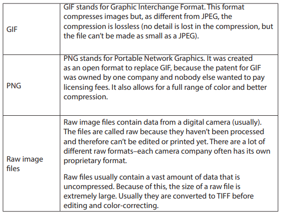
Application Activity 12.1.
1. Define an image.
2. Define vector graphics and raster graphics.
3. Define a pixel.
4. What is computer resolution?
5. How an image size is calculated?
6. Briefly describe two basic types of Graphics file formats.
7. List two categories of images in computer graphics.
8. In which graphic system are images easily scalable?
9. By using image taken with your camera or retrieved in your computer,
determine its size.
12.2 Images capturing tools
Activity 12.2

1. Describe what you see
2. What are the roles of the above devices?
3. Which device is most useful in our days in photo capturing? Why?
4. Describe the functioning of each device and describe the parts of each
12.2.1 Digital camera
a. Definition
A digital camera is a camera which produces digital images that can be stored in
a computer and displayed on screen.It records and stores photographic images in
digital format.
These stored images can be uploaded to a computer immediately or stored in the
camera to be uploaded into a computer or printer later.
Digital cameras use an image sensor instead of photographic film.
2. Digital camera parts
There are 10 basic camera parts to identify in today’s digital world. These parts will
inevitably be found on most cameras being digital compact or single-lens reflex
camera (SLR)
• Lens
The lens is one of the most vital parts of a camera. The light enters through the lens,
and this is where the photo process begins. Lenses can be either fixed permanently
to the body or interchangeable. They can also vary in focal length, aperture, and
other details.
• Viewfinder
The viewfinder can be found on all digital single-lens reflex cameras (DSLR) and some
models of digital compacts. On DSLRs, it will be the main visual source for imagetaking, but many of today’s digital compacts have replaced the typical viewfinder
with Liquid Crystal Display (LCD) screen.
• Body
The body is the main portion of the camera, and bodies can be a number of different
shapes and sizes. DSLRs tend to be larger bodied and a bit heavier, while there are
other consumer cameras that are a conveniently smaller size and even able to fit into
a pocket.
• Shutter Release
The shutter release button is the mechanism that “releases” the shutter and therefore
enables the ability to capture the image. The length of time the shutter is left open
or “exposed” is determined by the shutter speed.
• Aperture
The aperture affects the image’s exposure by changing the diameter of the lens
opening, which controls the amount of light reaching the image sensor. Some digital
compacts will have a fixed aperture lens, but most of today’s compact cameras have
at least a small aperture range.
• Image Sensor
The image sensor converts the optical image to an electronic signal, which is then
sent to the memory card. There are two main types of image sensors that are used
in most digital cameras: complementary metal-oxide-semi conductor (CMOS) and
charge-coupled device (CCD) Both forms of the sensor accomplish the same task,
but each has a different method of performance.
• Memory Card
The memory card stores all of the image information, and they range in size and
speed capacity.
• LCD Screen
The LCD screen is found on the back of the body and can vary in size. On digital
compact cameras, the LCD has typically begun to replace the viewfinder completely.
On DSLRs, the LCD is mainly for viewing photos after shooting, but some cameras do
have a “live mode” as well.
• Flash
The on-board flash will be available on all cameras except some professional grade
DSLRs. It can sometimes be useful to provide a bit of extra light during dim, low light
situations.
• User Controls
The controls on each camera will vary depending on the model and type. The
basic digital compacts may only have auto settings that can be used for different
environments, while a DSLR will have numerous controls for auto and manual
shooting along with custom settings.
Those parts can be seen on the following picture.
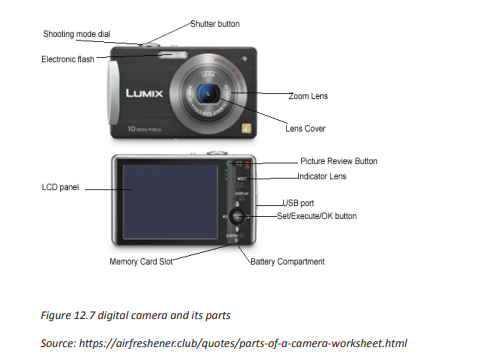
c. Importing pictures using USB cable
The images taken by using a camera are stored automatically in its memory. However,
for different purposes, the images can be printed or inserted in documents for
illustrations. The camera is then connected to the printer or the computer by using
a USB cable appropriately designed for such action. The fact of taking pictures from
the camera to the computer is called importing pictures.
The following steps are followed to successfully import a picture from camera to
computer by using a USB cable.
Step1
Connect one end of the USB cable to the port in your camera.
Step2
Connect the other end of the USB cable to the USB port in the computer. This may
be in the front or back of the computer.
Step3
Turn on the camera
Step4
A dialog box may appear on the screen. If it does, select “View Files” or “Open Folder.”
If the dialog does not appear, click the Windows “Start” menu, select “Computer” and
then choose the drive labeled for the connected camera.
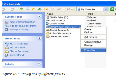
Step5
The pictures are probably located in a particular photo folder on the camera. Open
that folder. Drag individual photos from the folder to the desktop or some other
folder on the computer. All the photos can be selected by pressing “Ctrl-A” and then
pasted into a folder on the computer by pressing “Ctrl-V.”
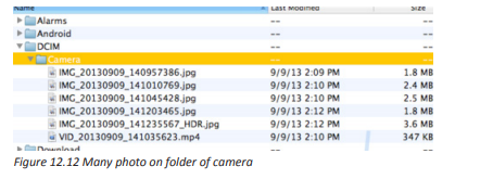
12.2.2 Scanner
a. Definition
A scanner is an electronic device which can capture images from physical items
(printed text, handwriting, photographic prints, posters, magazine pages, and
similar sources) and convert them into digital formats, which in turn can be stored in
a computer, and viewed or modified using software applications.
Very high resolution scanners are used for scanning for high-resolution printing, but
lower resolution scanners are adequate for capturing images for computer display.
b. The different parts of scanner
A scanner has the following five (5) parts visible externally:
(1)Start button, (2) Copy button, (3) Scan to E-mail button, (4) Scan to Web button,
(5) Scanner cover
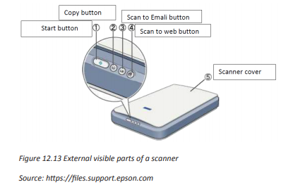
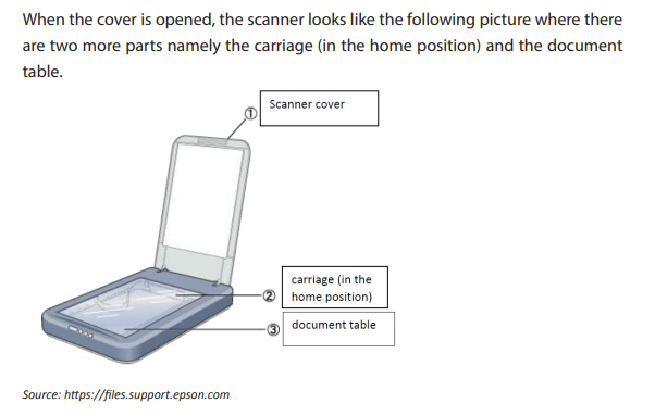

Application Activity 12.2.
1. Compare digital camera to scanner? List the importance of digital
camera in computer graphic.
2. With your camera, take a picture of the school computers, import it in
your computer and insert it in one of your text documents created in
MS Word.
3. At your school, what are the advantages and disadvantages of keeping
scanned documents?
4. By using your scanner in computer laboratory, scan your student card
and insert it in one text document created in MS Word.
5. Give the names of the 3 scanner parts indicated in the following image.
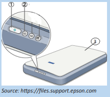
Area of graphics use
Computer graphics can be applied in various areas. Examples are such as follows:
12.3 Computer-Aided Design
Activity 12.3
After visiting the school library take different books and magazines and answer
the following questions:
1. Describe how the books and magazines covers look.
2. What is importance of having attractive picture on first page of any
magazine?
3. Which ways can be used to advertise your school?
4. List other fields where the photo are important to use
In engineering and architectural systems, the products are modeled using computer
graphics commonly referred as CAD (Computer Aided Design). In many design
applications like automobiles, aircraft, spacecraft, etc., objects are modeled in a
wireframe outline that helps the designer to observe the overall shape and internal
features of the objects.
12.3.2 Computer Art:
A variety of computer methods are available for artists for designing and specifying
motions of an object. The object can be painted electronically on a graphic tablet
using stylus with different brush strokes, brush widths and colors. The artists can also
use combination of 3D modeling packages, texture mapping, drawing programs
and CAD software to paint and visualize any object.
12.3.3 Entertainment:
Computer graphics methods are widely used in making motion pictures, music
videos and television shows. Graphics objects can be combined with live actions or
can be used with image processing techniques to transform one object to another.
12.3.4 Education and training:
Computer graphics can make better the understanding of the functioning of a
system. In physical systems, biological systems, population trends, etc., models make
it easier to understand. In some training systems, graphical models with simulations
help a trainee to train in virtual reality environment. For example, practice session or
training of ship captains, aircraft pilots, air traffic control personnel.
12.3.5 Image processing:
Image processing provides techniques to modify or interpret existing images. One
can improve picture quality through image processing techniques. For instance,
in medical applications, image processing techniques can be applied for image
enhancements and is been widely used for CT (Computer X-ray Tomography) and
PET (Position Emission Tomography) images.
12.3.6 Graphical User Interface:
GUI is commonly used to make a software package more interactive. There are
multiple window systems, icons, menus, which allow a computer setup to be utilized
more efficiently.
a. Logo (abbreviation of logotype, from Greek: is a graphic mark, emblem,
or symbol used to aid and promote public recognition. It may be of an
abstract or figurative design or include the text of the name it represents
as in a logotype or wordmark.
b. Advertising is communicated through various mass
media, including traditional media such as newspapers,
magazines, television, radio, outdoor advertising or direct mail; and new
media such as search results, blogs, social media, websites or text
messages. The actual presentation of the message in a medium is referred
to as an advertisement
c. An illustration is a decoration, interpretation or visual explanation of a
text, concept or process, designed for integration in published media,
such as posters, flyers, magazines, books, teaching materials, animations,
video games and films.
d. A magazine is a publication, usually a periodical publication, which is
printed or electronically published (sometimes referred to as an online
magazine). Magazines are generally published on a regular schedule and
contain a variety of content.
Conclusion
Computer Graphics involves ways in which images can be displayed, manipulated
and stored using computers. Computer graphics images can be categorised into
raster graphics, which as pixel-based graphics, and vector graphics, which are
mathematically represented. Computer graphics is applicable in various areas such
as computer-aided design, computer art, entertainment, as well as in education and
training.
Application Activity 12.3.
5. Why is it important to use graphics in advertisement?
6. In Rwanda, how computer graphics is used in entertainment?
7. How your school logo is designed? Explain how can you modify it using
computer graphic
8. Differentiate computer art to computer aid design
9. Discuss how computer graphics is used in entertainment in our country
12.4 Graphics software, features and editing tools
Activity 12.4
1. Describe what you see on the pictures below
2. How is it the appearance of those pictures?
3. In which way a picture can be modified?
4. Which tools can you use to modify or to create a picture?
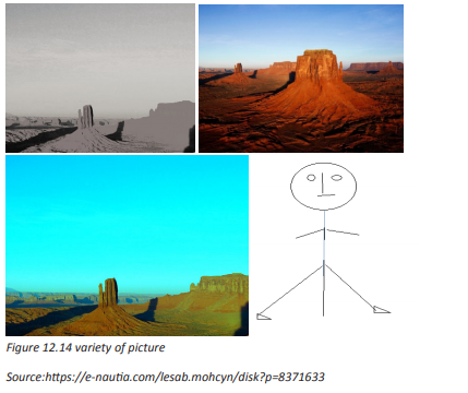
12.4.1 Graphic softwares
Computer graphics is mostly mastered by practicing; such as by writing and testing
programs that produce a variety of pictures. An environment that allows one to
write and execute programs is required. The environment should generally include
hardware for display of pictures, and software tools that written programs can use
to perform the actual drawing of pictures. This part presents the commonly used
software for producing graphics.
a. Microsoft Paint
Microsoft Paint or ‘MS Paint’ is a basic graphics/painting utility that is included in
all the Microsoft Windows versions. MS Paint can be used to draw, colour and edit
pictures, including imported pictures from a digital camera for example. MS Paint is
found in the windows start menu within the Accessories Folder.
The primary features of MS Paint are simple drawing tools that you can use to easily
draw on a blank canvas or existing image. Beyond that, Paint includes cropping,
resizing, rotating, skewing, and selection tools to further.
b. Microsoft Office Picture Manager
Microsoft Office Picture Manager (code named Microsoft Picture Library) is a raster
graphics editor introduced in Microsoft Office 2003 and included up to Office 2010.
The Basic image editing features include colour correct, crop, resize, and rotate.
With Microsoft Office Picture Manager, you can manage, edit, share, and view your
pictures from where you store them on your computer. There are picture editing
tools to crop, expand, or copy and paste.
Microsoft Office Picture Manager allows easily managing and editing. Picture
Manager is used to adjust the brightness and contrast of an image.
c. Adobe Photoshop
Adobe Photoshop is a raster graphics editor developed and published by Adobe
Systems for MacOS and Windows.
Adobe Photoshop is the predominant photo editing and manipulation software on
the market. Its uses range from full featured editing of large batches of photos to
creating intricate digital paintings and drawings that mimic those done by hand.
12.4.2 Graphic features
12.4.2.1 Definition
Graphic features are pictures and other images that accompany a piece of text to
improve its meaning for the reader. Some examples of graphic features include
photographs, drawing, maps, charts and diagrams. While graphic features may
sometimes be purely decorative, they are more often used to make the meaning of
a text clearer.

12.4.3 Graphic editing tools
a. Tools in MS-Paint
Starting the Microsoft Paint program in Windows
1. Choose Start->All Programs->Accessories->Paint.
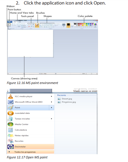
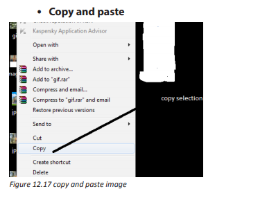
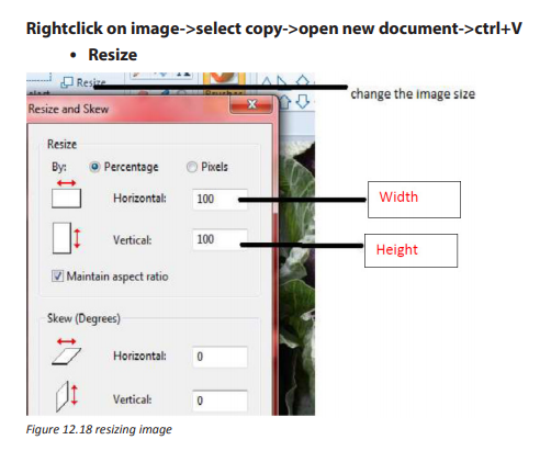

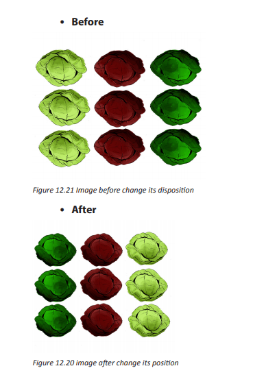
c. Tools in Ms Office picture manager
Step1.
Starting the Microsoft office picture manager
Microsoft Office comes with its own Picture Manager. You can open the Picture
Manager by clicking Start, choosing All Programs (or Programs), choosing the
Microsoft Office folder, choosing Microsoft Office Tools, and clicking Microsoft
Picture Manager.
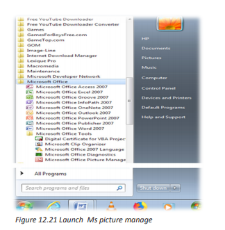
Step2.
Using Picture Manager editing tools for adjustment:
• Brightness and contrast: Select the brightness and contrast menu entry.
The task pane will display a range of control sliders; you can use these to
adjust any exposure issues (too bright, too dark etc).
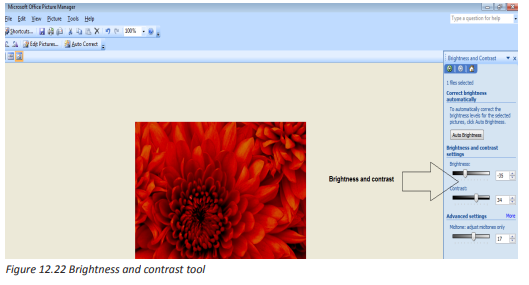
• Color: Select the Color option from the Edit Pictures menu. Use the sliders
to adjust the Hue and Saturation.
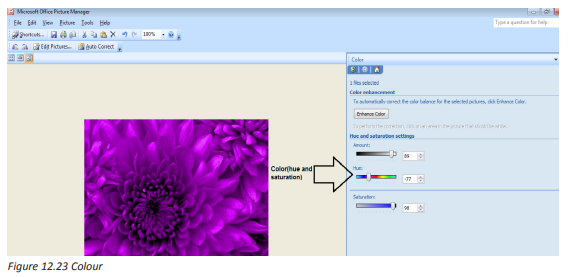
• Crop: Select the Crop option. You will notice the crop is previewed on the
image; you can click and drag the crop area to reposition it. Grab the little
black crop marks in the corners or on the edges to scale the image.
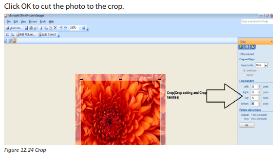
Red-eye removal: Select Red eye removal from the Edit Pictures menu.
Click the mouse curser several times over all the red eye areas you want to
remove, and then click OK.
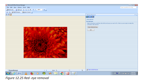
Resize your picture: On the Edit Pictures menu select Re-size to display the
resize.
Choose the Predefined setting of Document – Small (800 x 600), this is perfect for
working in Word without slowing it down. This will also reduce the size of the file,
perfect if you intend on emailing the document as an attachment.

After editing a picture, you can either File > Save to save the photo in its modified
format, or File > Save As… to give it a new filename (allowing you to keep the original
source file intact).
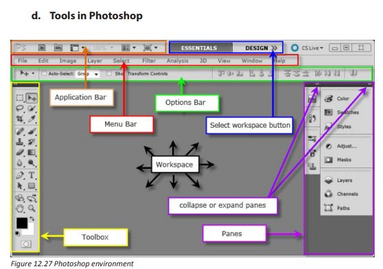
1. Photoshop editing tools
To change the image size, go through these steps:
Start->photoshop->File->open (choose an image where it is stored)->image
(in menu bar)
->image size->fill the new width and height in pixel dimension->ok
For this exercice, consider the image below which is with its original dimensions:


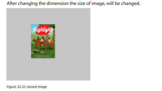
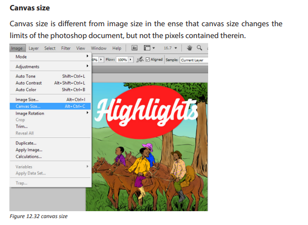
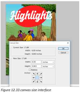
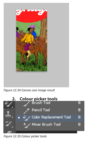

In Photoshop, Adobe introduced the Color Picker to make the selection of a color
even easier. (To access the Color Picker with a painting tool selected, click anywhere
in the image area and drag to select a color.
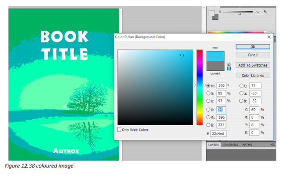
Magic wand
The Magic Wand Tool, known simply as the Magic Wand, is one of the oldest selection
tools in Photoshop. Unlike other selection tools that select pixels in an image based
on shapes or by detecting object edges, the Magic Wand selects pixels based color
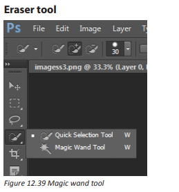
Eraser
An eraser is an article of stationery that is used for removing writing from paper or
skin. Erasers have a rubbery consistency and come in a variety of shapes, sizes and
colours.

Gradient tool
A gradient is a set of colors arranged in a linear order, sometimes known as the
“gradienttool” or “gradient fill tool”: it works by filling the selection with colors
from a gradient.
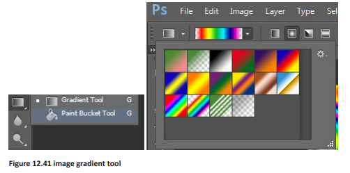

Paint bucket
The paint bucket tool generally comes along with image editing software. What
it does is fill an area on the image with a selected color. The tool usually fills to the
boundaries of a solid color. As an example if you have a black box and apply red with
the paint bucket tool it will convert the entire box to red.
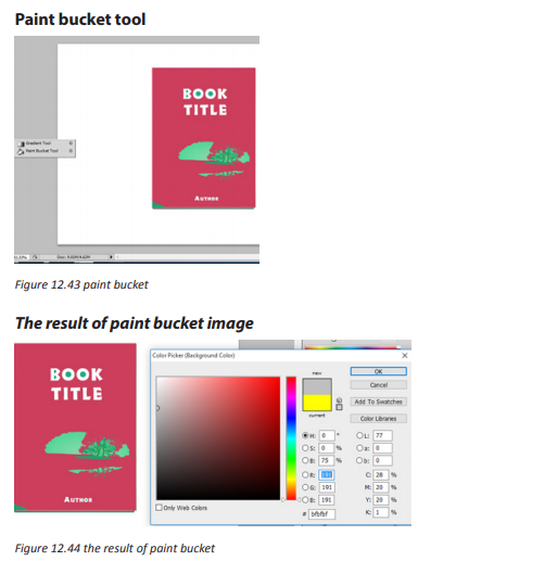
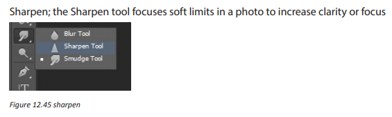
Smudge
The smudge tool is used to smear paint on your canvas. The effect is much like
finger painting. You can use the smudge tool by clicking on the smudge icon and
clicking on the canvas and while holding the mouse button down, dragging in the
direction you want to smudge.

Clone stamp tool
Clone stamp is used in digital image editing to replace information for one part of
a picture with information from another part. In other image editing software, its
equivalent is sometimes called a clone brush.

Shape
A shape is the form of an object or its external boundary, outline, or external surface,
as opposed to other properties such as color, texture or material composition

Rectangle: is a quadrilateral with four right angles a plane figure with four straight
sides and four right angles, especially one with unequal adjacent sides, in contrast
to a square
Lasso tool: it is used to create a selection area within or around a particular object.
The difference is that it allows the user to more easily select along individual short
paths on difficult object limit where the tool can’t be used

Polygon lasso
The Polygonal Lasso Tool is hiding behind the standard Lasso Tool in the Tools
panel. Once you’ve selected the Polygonal Lasso Tool, it will appear in place of the
standard Lasso Tool in the Tools panel.


Rotate
This tool is used to rotate the active layer, a selection or a path. When you click on
the image or the selection with this tool, a grid or an outline is superimposed and a
rotation information dialog is opened. There, you can set the rotation axis, marked
with a point, and the rotation angle.


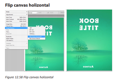
Application Activity 12.4.
1. What is the importance of Ms Paint in computer graphics?
2. Differentiate Photoshop from MS office picture manager
3. Discuss the use of Ms Office picture manager in graphics
4. Differentiate Paint from Photoshop
5. What is the use of Lasso tool in Photoshop
6. Distinguish image size to canvas size
7. What is the use of Gradient Tool?
12.5 Basic Graphic elements
Activity 12.5
Observe the picture above and answer the following questions:
1. Describe what you see on the picture
2. What are the elements which make this picture?
3. how can you put different parts of this image
12.5.1 Graphic elements
Graphic elements are the simplest building blocks of graphics. Just as bricks are the
basic elements of a building, graphic elements are used to create graphics.
12.5.2 Basic graphic element types
The basic graphic elements are the following:
Line is probably the most fundamental of all the elements of design. A more usable
definition might be that line is the path of a dot, point etc. through space and that
is always has more length than thickness. Lines are not all the same, especially in art

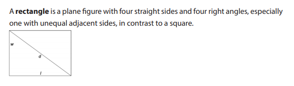
A brush is a tool with bristles, wire or other filaments, used for cleaning, grooming
hair, make up, painting, surface finishing and for many other purposes.

Polyline
A polyline is a connected sequence of straight lines. To the eye, a polyline can appear
as a smooth curve. Simple polyline attributes are colour and thickness. The simplest
polyline is a single straight line segment. A line segment is specified by its two
endpoints, such as (x1, y1) and (x2, y2). When there are several lines in a polyline,
each one is called an edge, and two adjacent lines meet at a vertex.
The edges of a polyline can cross one another but a polyline does not have to be
closed. A polygon has its first and last points connected by an edge. If no two edges
cross, the polygon is called a simple polygon. An example of a polyline is shown in
figure 12.60 and a polygon is shown in figure 12.61
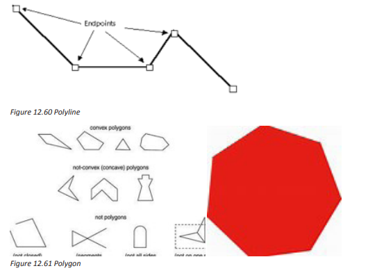
The polygon element defines a closed shape consisting of a set of connected straight
line segments. The last point is connected to the first point.
Text
Some graphics devices have two distinct display modes: text mode and graphics
mode. In text mode, text is generated using a built-in character generator. Text in
graphics mode is drawn. Text attributes are such as colour, size, font, spacing and
orientation.
Filled Regions
A filled region is a shape filled with some colour or pattern. An example is a filled
polygon as shown in figure.

Application Activity 12.5.
1. Describe the graphic element?
2. Describe basic elements in computer graphics
3. Differentiate an oval to a circle
4. Describe the use of brush in computer graphic?
END UNIT ASSESSMENT
A. Written assessment
Define the following terms:
• Brush
• Shape
• Lasso tool
• Bitmap
• Advertisement
1. Match the following tools in column A with their corresponding use in

2. What is polygon? Give an example
3. Explain the importance of computer graphic in decoration service
4. Write in full words the following abbreviation and explain them:
JPEG - TIFF - PNG
5. Distinguish 8-bit colour to high colour graphics
6. What is the use of USB port on digital camera
7. Differentiate 2D image to 3D image
8. Discuss the difference between Ms Paint and Adobe Photoshop
9. In Rwanda, computer graphics are used in advertising and entertainment.
Discuss
B. Practical work
Create a simple image using some of the drawing tools in Paint(Pencil, brush and shapes)
a. Selecting and moving parts of an image
b. Selecting and copying parts of an image
c. Save the image in JPG format
d. Copy that image in a word document
1. Using Adobe Photoshop, draw a ball as shown bellow

2. Create a line, polygon and a square using Paint. Make the shape outlines
coloured and filled with effects where possible. Save the file as SHAPES
3. Take a picture of yourself using a digital camera and edit the photo in
a way you wish using various tools on the toolbox and menu. In case
of absence of camera, use any available photo on your computer and
perform editing functioning to crop, resize, rotate and change the light of
the picture.
UNIT 13: MULTIMEDIA
Key unit competency
To be able to explain the different use of multimedia and interactive multimedia
applications and to use multimedia software to create video.
Introductory Activity
Observe the figure below and answer the following questions.
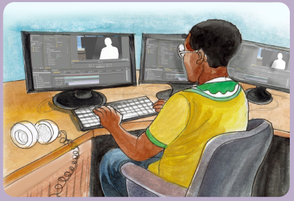
1. Describe what you see.
2. What materials or tools are used?
3. Explain the method used to achieve their objectives?
4. What is the importance of multimedia in meetings organization?
5. What else technologies can be used to share information between
individuals and institutions?
13.1. INTRODUCTION TO MULTIMEDIA
Activity 13.1.
1. What do you understand by Multimedia?
2. Discuss the role of multimedia in daily life.
3. Discuss the software used in multimedia.
13.1.0 Definition
Multimedia is the content that uses a combination of different forms of content
such as text, audio, images, animations, video and interactive content. Multimedia
contrasts with media that uses only rudimentary computer displays such as textonly
or traditional forms of printed or hand-produced material.
Multimedia can be recorded and played, displayed, interacted with or accessed
by information content processing devices, such as electronic devices, but can also
be part of a live performance. Multimedia devices are electronic media devices
used to store and experience multimedia content.
13.1.1 Different types of media
Media are the collective communication outlets or tools used to store and deliver
information or data. Modern media come in many different formats, including
print media (books, magazines, newspapers), television, movies, video games,
music, cell phones, various kinds of software, and the internet.
1. Print Media
The term ‘print media’ is used to describe the traditional or “old-fashioned” printbased
media, including newspapers, magazines, books, and comics or graphic
novels.
2. Television
Television (TV) is a telecommunication medium used for transmitting moving
images in monochrome (black and white), or in colour, and in two or three
dimensions and sound. The term can refer to a television set, a television
program (“TV show”), or the medium of television transmission. Television is a mass
medium for advertising, entertainment and news.
3. Movies
Movies, also known as films, are a type of visual communication which
uses moving pictures and sound to tell stories or inform (help people to learn).
People in every part of the world watch movies as a type of entertainment, a way
to have fun.
4. Video Games
A video game is an electronic game that involves interaction with a user
interface to generate visual feedback on a video device such as a TV
screen or computer monitor.
13.1.2 Media applications
Multimedia finds its application in various areas including, but not limited to,
advertisements, art, education, entertainment, engineering, medicine, mathematics,
business, scientific research, spatial temporal applications, etc.. Several examples
are as follows:
1. Creative industries
Creative industries use multimedia for a variety of purposes ranging from fine arts,
to entertainment, to commercial art, to journalism, to media and software services.
2. Commercial uses
Much of the electronic used by commercial artists and graphic designers is multimedia.
Exciting presentations are used to grab and keep attention in advertising. Business
to business, and interoffice communications are often developed by creative
services firms for advanced multimedia presentations beyond simple slide shows to
sell ideas or liven up training.
3. Entertainment and fine arts
Multimedia is heavily used in the entertainment industry, especially to develop special
effects in movies and animations (VFX, 3D animation, etc.). Multimedia games
are a popular pastime and are software programs available either as CD-ROMs or
online. Some video games also use multimedia features. Multimedia applications
that allow users to actively participate instead of just sitting by as passive recipients
of information are called interactive multimedia. In the arts, there are multimedia
artists, whose minds are able to blend techniques using different media that in some
way incorporates interaction with the viewer.
4. Education
In education, multimedia is used to produce computer-based training courses
(popularly called CBTs) and reference books like encyclopedia and almanacs. A
CBT lets the user go through a series of presentations, text about a particular topic,
and associated illustrations in various information formats. Edutainment is the
combination of education with entertainment, especially multimedia entertainment.
5. Journalism
Newspaper companies all over the world are trying to embrace the new phenomenon
by implementing its practices in their work.
6. Engineering
Software engineers may use multimedia in computer simulations for anything
from entertainment to training such as military or industrial training. Multimedia
for software interfaces are often done as collaboration between creative
professionals and software engineers.
7. Mathematical and scientific research
In mathematical and scientific research, multimedia is mainly used for modeling and
simulation. For example, a scientist can look at a molecular model of a particular
substance and manipulate it to arrive at a new substance.
8. Medicine
In medicine, doctors can get trained by looking at a virtual surgery or they can simulate
how the human body is affected by diseases spread by viruses and bacteria and
then develop techniques to prevent them. Multimedia applications such as virtual
surgeries also help doctors to get practical training.
13.1.3. Hardware and software requirements
Multimedia is the one industry which requires different equipments to be used. It
requires Hardware and Software equipment as listed below.
a. Hardware
27” standalone iMac
• 15” monitor with multiple video inputs
• scanner
• DV/DVD recording :is an optical disc recorder that uses optical
disc recording technologies to digitally record analog or digital signals
onto blank writable DVD media
• DVD/VCR recording deck: is an electromechanical device that records
analog audio and analog video from broadcast television or other source
on a removable, magnetic tape videocassette, and can play back the
recording.
• DV/VCR recording deck
• DV recording deck
• Whiteboard
b. Software used in multimedia

Application Activity 13.1.
1. Explain how multimedia can be applied in education
2. State different software and hardware required for multimedia applied
in education.
3. What kind of headphone can you use to protect your ears from the
noise
13.2. Interactive multimedia
Activity 13.2.
4. What do you understand by Hyperlink?
5. In PowerPoint presentation, discuss different steps followed to create
hyperlinks.
13.2.1 PowerPoint presentation
a. Creating Hypertext in the same document
Whenever the internet is used in Microsoft office 2013, hyperlinks are used to
navigate from one webpage to another. Web addresses or email addresses are
included in PowerPoint presentation through hyperlinks.
Hyperlinks have two basic parts: the address of the webpage, email address,
or other location they are linking to, and the display text (which can also be a
picture or shape). For example, the address could be https://www.youtube.com,
and YouTube could be the display text. In some cases, the display text might be
the same as the address. When creating a hyperlink in PowerPoint, choose both the
address and the display text or image.
1. Steps Creating Hyperlink
Step1: Select the image or text you want to make a hyperlink.
Step2: Right-click the selected text or image, then click Hyperlink.
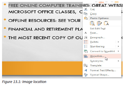
Step3: The Insert Hyperlink dialog box will open. You can also get to this dialog
box from the Insert tab by clicking Hyperlink.
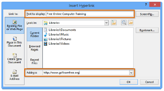
Figure 13.2: Dialog box for inserting Hyperlink
Step4: If you selected text, the words will appear in the Text to display field at the
top. You can change this text if you want.
b. Creating Hyperlink to another presentation
You can easily link to a specific slide in another presentation. Follow these steps:
Step1: Select the object on the slide that you want to use for the hyperlink.
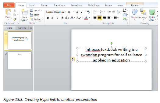
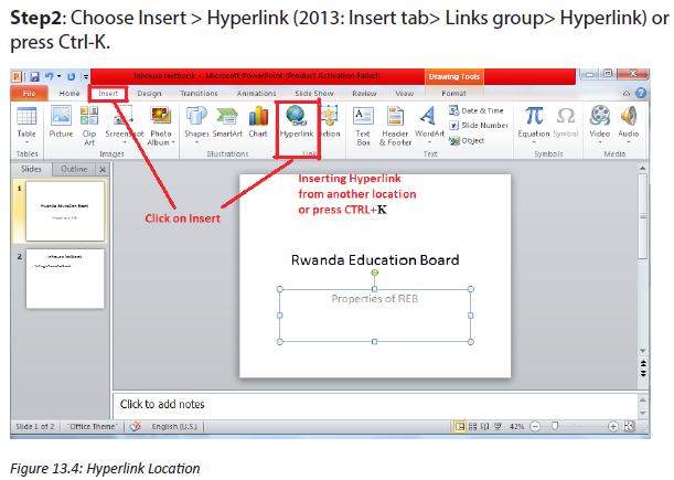
Step3: In the insert Hyperlink dialog box, choose Existing File or Web Page from
the Link to bar at the left.

Step4: Click the Bookmark button.
The Select a Place in Document dialog box opens, listing all the slides in the
presentation to which you’re linking.
Step5: Select a Place in Document dialog box
Choose the slide you want and click OK.
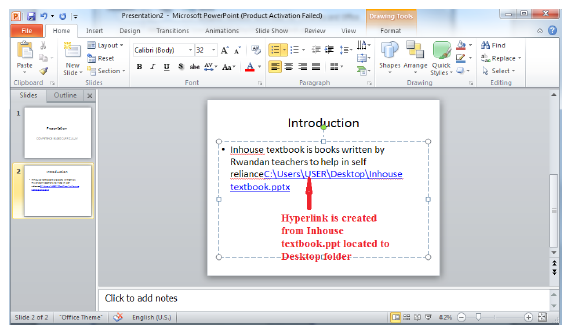
Note: If your object is an Action Button, the Action Settings dialog box opens.
Choose the Hyperlink To option. From the drop-down list, choose Other PowerPoint
Presentation. Navigate to the presentation and click OK. The Hyperlink to Slide
dialog box opens, which is just like the Select Place in Document dialog box, listing
the slides. Choose the one you want and click OK twice.
c. Creating Hyperlink to a file
Step1: Press CTRL+K
Step2: Right-click the selected text or image, then click Hyperlink. The Insert
Hyperlink dialog box will appear.
Step3: On the left side of the dialog box, click Existing File or Webpage.
Click the drop-down arrow to browse for your file.
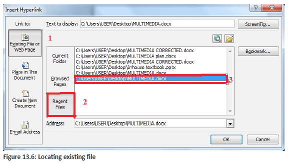
After selecting the desired file, Click OK button
Step4: Desired Hyperlinks prompted
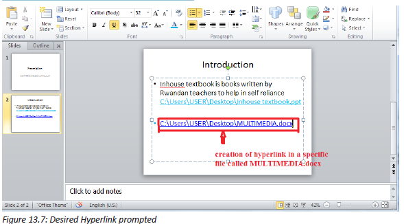
d. Creating a hyperlink to an email address
Step1: Right-click the selected text or image, then click Hyperlink.
Step2: The Insert Hyperlink dialog box will open.
Step3: On the left side of the dialog box, click Email Address.
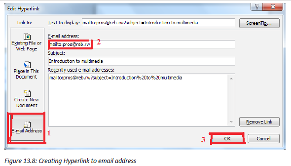
Step4: Type the email address you want to connect to in the Email Address box,
then click OK.
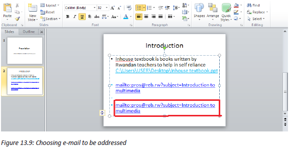
PowerPoint often recognizes email and web addresses as you type and will format
them as hyperlinks automatically after you press the Enter key or spacebar.
If you plan to display your presentation on a different computer, your hyperlink
to another file may not work. You have to make sure that you have a copy of the
linked file on the new computer and always it is good to test hyperlinks before
giving a presentation.
Application Activity 13.2.
1. In Computer lab, create PowerPoint presentation
2. Create hyperlink in the same document,Create hyperlink to another
presentation,
3. Create hyperlink to another file and
4. Create Hyperlink to email address
5. How can you protect your hyperlink created to an email address for not
being hacked?
13.3. Creating action buttons
Activity 13.3.
1. What do you understand by Action button in PowerPoint presentation?
2. Discuss different types of action buttons and their roles.
3. In an opened PowerPoint presentation, create an action button.
a. Action Buttons play or stop
Another tool used to connect to a webpage, file, email address, or slide is called
an action button. Action buttons are built-in button shapes added to a
presentation and set to link to another slide, play a sound, or perform a similar
action.
Action buttons can be inserted on one slide at a time, or an action button can be
inserted to show up on every slide. The second option can be useful if every slide
has to be linked back to a specific slide, like the title page or table of contents.
To insert an action button on one slide:
Step1: Click the Insert tab.
Step2: Click the Shapes command in the Illustrations group. A drop-down menu
will appear with the action buttons located at the very bottom.

Step3: Select the desired action button.
Step4: Insert the button onto the slide by clicking the desired location. The Action
Settings dialog box will appear.
Step5: Select the Mouse Click or Mouse Over tab. Selecting the Mouse Click tab
means the action button will perform its action only when clicked. Selecting
the Mouse Over tab will make the action button perform its action when the
mouse is moved over it.
Step6: in the Action on click section, select Hyperlink to: then click the dropdown
arrow and choose an option from the menu.
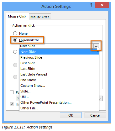
Step7: Check the Play Sound box if you want a sound to play when the action
button is clicked. Select a sound from the drop-down menu, or select other
sound to use a sound file on your computer.
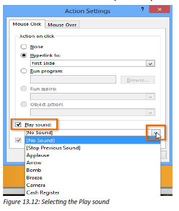
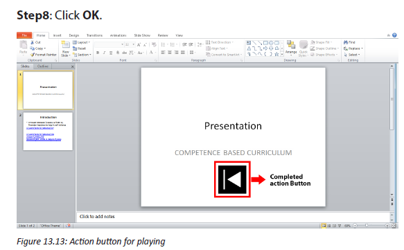
b. Action Button for playing a CD
When you want to play a CD, the following action buttons must take effect, and
you need to follow the same process for creating action buttons to create them.
1. Action button for previous media
2. Action button for next media
3. Action button for start or begin or play
4. Action button for end or stop
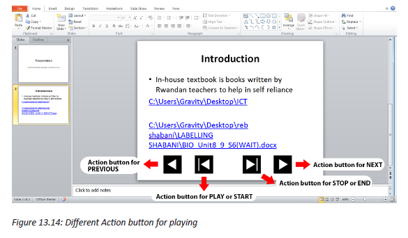
Application Activity 13.3.
1. In a created PowerPoint presentation
a. Create action button for playing an audio song
b. Create action button for next and previous song
2. Create action button for stopping song Tom who is a friend of Antoine
is working in video and audio editing. Antoine has a birthday party of
his son and he wants to take an audio sound of each event. Tom told
him that he will do it as an expert and a friend for free, what are the
advantages for Antoine.
3. In a slide, create an action button to play a movie that you selected.
13.4. Digital Audio recording and Editing
Activity 13.4.
1. What is an audio sound?
2. Discuss the format of an audio sound that you may know.
3. What do you thing about audio sound recording?
4. Discuss which software can edit an audio sound and how?
An audio file format is a file format for storing audio. There are various audio file
formats and they all encode audio data in different ways. There are two different
approaches; compressed or non-compressed formats.
1. Uncompressed formats
Uncompressed audio formats are always lossless, meaning that all original audio
information is retained. If there is unlimited storage space, an uncompressed - or
lossless file format is the way to go. While working with audio (ie making music),
also stick with uncompressed formats.
There are two main format options here, AIFF and WAV. Neither of these requires a
license to use.
WAV is the most recommended as it is more widely used and supported.
Uncompressed audio in CD-quality (sample rate of 44.1 kHz and a bit depth of 16
bits) takes about 10MB for one minute of stereo audio.
1. Compressed formats
Compressed audio formats are primarily lossy formats, meaning that audio
information is reduced. If an audio needs to be distributed over the internet, a
compressed format is the best option.
Although MP3 is very popular but it does require a license, even for audio
distribution. The existing and most used audio formats are:
a. 3GP and 3G2, (3GPP file format) is a multimedia container
format defined by the Third Generation Partnership Project (3GPP) which
is multimedia services. It is used on 3G mobile phones but can also be
played on some 2G and 4G phones.
b. MP3 (MPEG-1 Audio Layer-3) is a standard technology and format for
compressing a sound sequence into a very small file (about one-twelth the
size of the original file) while preserving the original level of sound quality
when it is played. MP3 provides near CD quality audio.
c. WAVE or WAV format is the short form of the Wave Audio File Format
(rarely referred to as the audio for Windows). WAV format is compatible
with Windows, Macintosh or Linux. Despite the fact that the WAV file can
hold compressed audio, the most common use is to store it just as an
uncompressed audio in linear PCM (LPCM).
13.4.1 Use of different tools to record sound
a. Microphone
A microphone is a device that captures audio by converting sound waves into
an electrical signal. A microphone placement technique is how microphones are
positioned in relation to the instrument or voice. Technique is the general strategy
used in microphone placement. The location of the microphones while recording
will make a big difference in the got sound. Microphones can just be plunked
down and recorded, but a little experimentation can go a long way in getting a
better sound.
Process to record sound using Microphone
The process to record sound depends on the version of MS Windows used. Up to
the MS Windows 7, follow the next steps. The steps will be almost similar if you use
new versions of MS Windows.
Step1: Click on the Start button, and then click All Programs > Accessories >
Entertainment > Volume Control to display the Volume Control box.


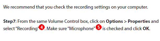

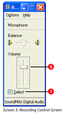
Application Activity 13.4.
1. What is the best audio format recommended? Explain why.
2. A part from the musical instruments described above, explain other five
musical instruments used to deal with sound.
3. In Rwandan culture, describe the elements which can be linked by this
topic to manage sounds?
13.4.2 Editing Audio Sound
Activity 13.5.
1. What do you think about audio editing?
2. Discuss software used when editing audio sound.
3. Explain what are the processes to edit audio sound?
Audio editing is the process of manipulating audio to alter length, speed, and
volume or to create additional versions such as loops. Audio editing is almost
always done using a computer and audio editing software but used to be done
with analogue tape and razor blades by splicing and taping in a pre-digital world.
a. Fade-In and Fade-Out
In audio engineering, a fade is a gradual increase or decrease in the level of
an audio signal. The term can also be used for film cinematography or theatre
lighting in much the same way (see fade- filmmaking and fade- lighting).
A recorded song may be gradually reduced to silence at its end (fade-out), or may
gradually increase from silence at the beginning (fade-in).
As there are many software applications used in multimedia for sound editing
and management, in this section, let us use Audacity. Audacity is a free and
open-sourcedigital audio editor and recording application software, available for
Windows, macOS/OS X and Unix-like operating systems. Audacity was started in
the fall of 1999 by Dominic Mazzoni and Roger Dannenberg at Carnegie Mellon
University and was released on May 28, 2000 as version 0.8.
As of October 10, 2011, it was the 11th most popular download from SourceForge,
with 76.5 million downloads.Audacity won the SourceForge 2007 and 2009
Community Choice Award for Best Project for Multimedia. In March 2015, hosting
was moved to FossHub and by February 21, 2017 it had exceeded 51.8 million
downloads there. It is under the terms of the GNU General Public License.
Steps to Fade In/Out
Step1: Open Audacity software
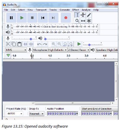
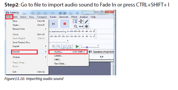


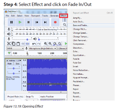
Step5: After selecting effect, you can Fade In/Out depending on what you want
to do. The below figure shows the process of sound fade in when using audacity
software.

The figure below shows the process of FADE Out, when an audio song is being
Faded out
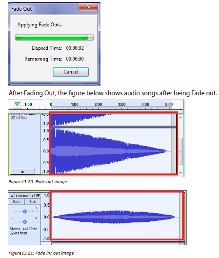
b. Crop
To crop audio is to make it start where you want to be started and end at the point
you wish to be ended. The following are the steps in adobe flash player to crop an
audio sound.
Step1: Importing audio in audacity software, and select the area to crop from to
where you don’t want to be played.
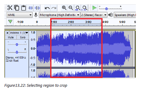
Step2: Click on cut sign, the unwanted area will be removed and you remain with
the wanted part.
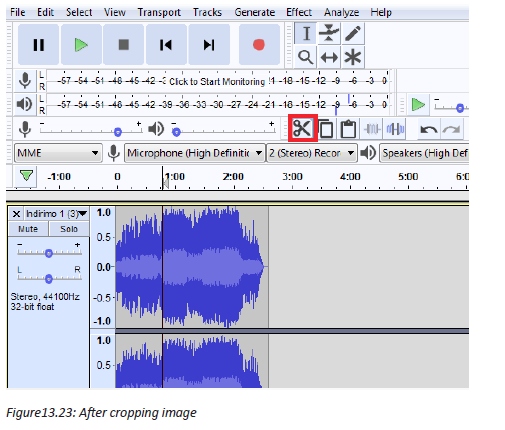
c. Echo
Echo is a reflection of sound that arrives at the listener with a delay after the
direct sound. The delay is proportional to the distance of the reflecting surface
from the source and the listener.
Here is how you can have echo in your audio sound:
Step 1: In audacity software, click on Echo from Effect
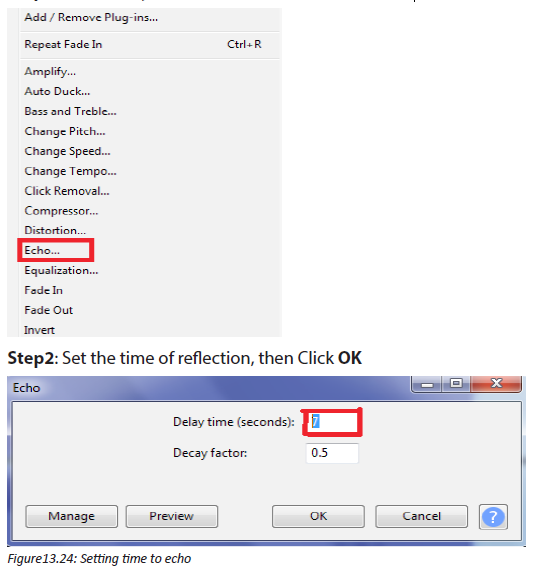
d. Increasing or decreasing volume,
Open the audio file in Audacity. Remember, do not make trim changes
in Audacity. On the left side of the screen is the gain (in dB), which can be adjusted
to increase or decrease the volume of the recording.

Once you have adjusted the volume of the recording to your liking, save the audio
file in its original location. When you reopen the file in Proclaim the audio level
changes will be reflected.
e. Reducing noise
Step1: In imported sound Audacity Software, Select a Region of Pure Noise
Hopefully you have a good sample area, but Audacity can do amazing things even
if only with a few seconds of data. You can see in the bottom track a grey area that
is selected as our noise profile.
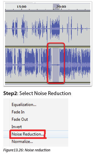
Step3: Click Get Noise Profile
When you click this, the window will go away and it won’t look like Audacity did
anything at all, but in fact you’ve just told it, “This is what noise looks like”.
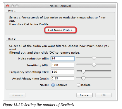
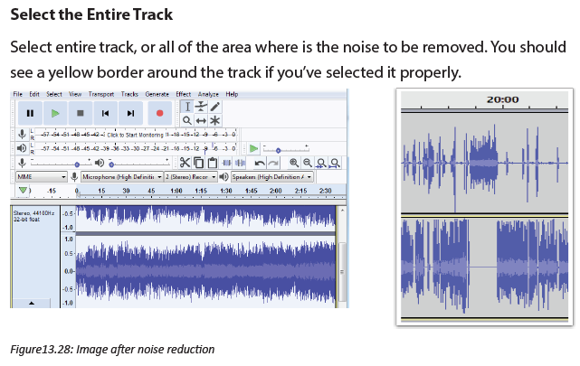
f. Humming
After removing noise vocals, you need to select all region of sound to remove
again noise; in that case you will find the sound is humming.
Step1: Select the region where is the hum, Go to effect and select Noise reduction
then click on Get Noise Profile, the image below will be produced
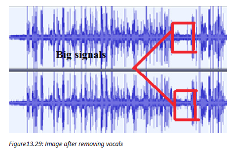
Step2: Select the region of the whole song, go to effect and Select Noise
Reduction the click OK, the figure above will be produced which is different from
the above figure.
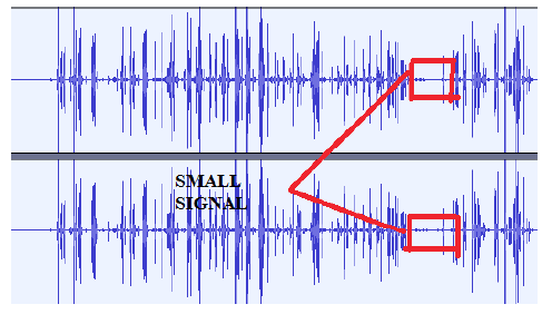
Figure13.30: Image after humming
g. Remove vocal
Go to Effect, Amplify and choose a negative level value, then click OK. You want
to play around with the exact values until you find one that works best for your
specific track.
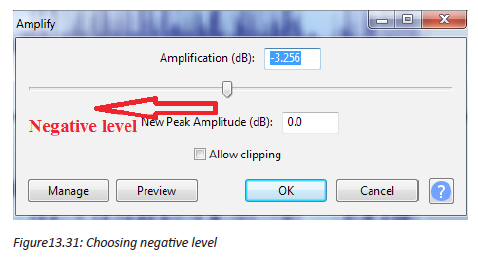
h. Equalizer
Equalization is the process of adjusting the balance
between frequency components within an electronic signal. The most well-known
use of equalization is in sound recording and reproduction but there are many
other applications in electronics and telecommunications. The circuit or equipment
used to achieve equalization is called an equalizer. To do this, follow these steps.
Step1: With imported sound, select Effect and Click on Equalization
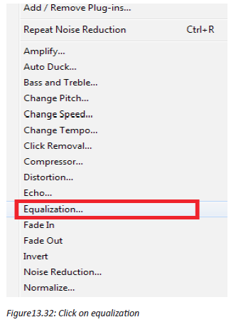
Step2: Set Equalizer to the needed Decibel
After clicking on Equalization, equalization table will appear, measured in decibel,
the line in green was located at the level of 0dB, then you drag to the appropriate
equalization you want to be, here it is dragged from 0dB to 15dB
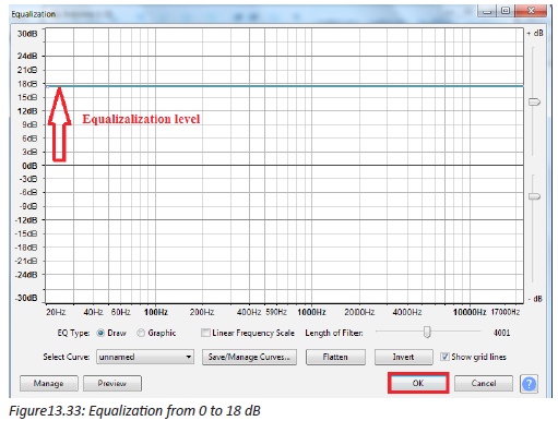
Application Activity 13.5.
1. Using audacity software that you have installed on your computer, do
the following:
a. Use a smartphone/ digital camera, etc and record a sound
b. Import the recorded sound and do all necessary operation to be an
audible or quality sound such as crop Fade In/out, remove vocals,
remove noise
c. Create sound humming
d. Set different Decibels to create equalization.
13.4. Digital Video recording and editing
Activity 13.6.
1. In group of five students, discuss different video formats and software
to edit videos
2. What is the preparation required to take a video that may be displayed
in your classroom?
13.4.1 Various Video format
A video file format is a type of file format for storing digital video data on
a computer system. Video is almost always stored in compressed form to reduce
the file size.
a. Audio Video Interleave (.avi)
Audio Video Interleave known by its initials AVI, is a multimedia container format
introduced by Microsoft in November 1992 as part of its Video for Windows
software. AVI files can contain both audio and video data in a file container that
allows synchronous audio with video playback Flash Video (.flv, .swf )
b. .M4V and .MP4
.m4v and .mp4 are very similar and are both part of MPEG-4 which was based on
the Quicktime file format. .m4v was created by Apple as an extension of MPEG-4
with the option of proprietary Apple DRM to keep their files from playing on nonapple
devices.
13.4.2 Digital video Recording
A digital video recorder (DVR) is a consumer electronics device designed for
recording video in a digital format within a mass storage device such as USB
flash drive, hard disk drive or any other storage device. There are many software
to manage and edit a digital video. Some are proprietary while others are Open
Source software.
Set up your recording environment
With Snagit (Snagit is a screenshot program that captures video display and audio
output. Originally for the Microsoft Windows operating systems, recent versions
have also been available for macOS, but with fewer features.), it doesn’t take long
to create great videos of any computer-related process. To begin, close or minimize
any programs not involved in the process, especially ones that might trigger alerts
or popups. Then, open the programs you want to record and arrange them on your
screen. The steps to record an audio are the Following.
a. Launch Snagit
Open Snagit and select the video tab. Start with your webcam on if you want to
explain what your video will demonstrate or give it a personal touch.
b. Prepare to record
Write down a list of the key talking points or things you want to be sure to include
in your video. It won’t take long, and will be helpful to reference when you’re
recording. With your talking points in hand, click the capture button in Snagit, and
select part of the screen to record.
c. Make a test recording
Check that microphone audio recording is on, and system audio (the noises that
come from your computer) is on if you need it in your video. Click record to do a
quick test. While recording, go through a couple of the steps of your process. Then,
stop the test recording and play it back to make sure everything worked the way it
should.
d. Record your video
Once your test recording looks and sounds the way you want it, you’re ready to
record your video. Click the Capture button, select the recording area, and click
record. The countdown will play and then you can talk through your entire process.
If you make a mistake or stumble over a portion, instead of restarting the
recording, reset to a point in the process just before the mistake and go from there.
You can remove mistakes later.
e. Reviewyour video
When you are finished, stop your recording. The video is brought into the software
editor, where you can watch it and cut out any mistakes.
f. Share your video
Use the share menu to save your final video to your computer, or send it to
Screencast.com, Youtube, or Google Drive for immediate sharing.
13.4.3 Digital video editing
a. Video editing
Video editing is the process of manipulating and rearranging video shots to create
a new work. Editing is usually considered being one part of the post production
process.
Video clips are short clips of video, usually part of a longer recording. The term
is also more loosely used to mean any short video less than the length of a
traditional television program. The steps are as follow:
Step1: Select Edit, New Symbol then press OK
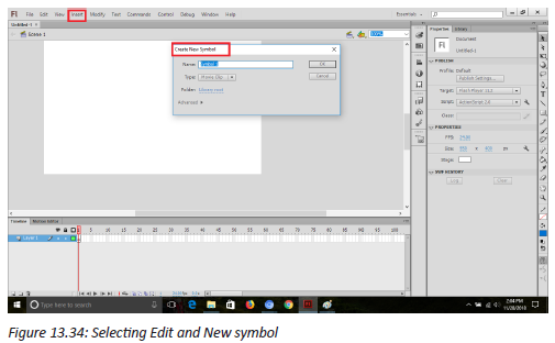
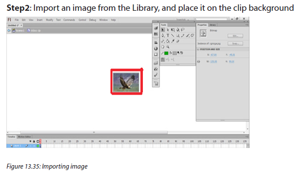
Step3: Press CTRL +B, to highlight the background of animated image for being
edited using different tools.
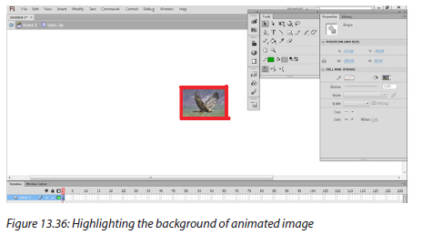
Step4: Use different tools to do animation of the imported image in the
background in different frames chosen.

Step5: Select all Frames and right click to Copy them to the next frames
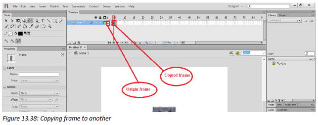
Step6: Select all frames and right click then press to Reverse frames for reversing
the created frames.
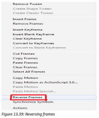
Step7: Click Scene1 to come back to scene one and import another image
Step8: Resizing the image using free transform tool and zoom in and out
depending on the desired motion.

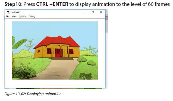
Step 11: Create new Layer, and go to windows then click on Library
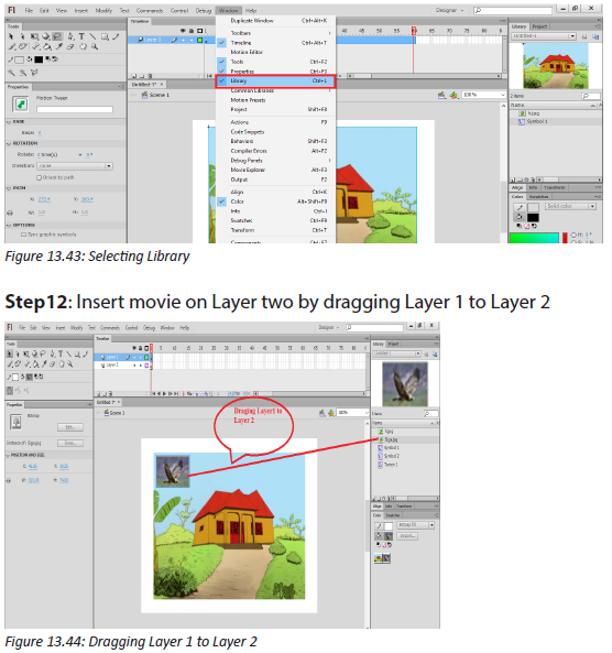
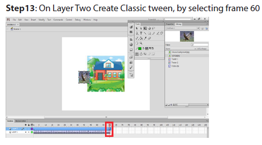
Figure 13.45: Classic tween creation
Step14: Change moving position and Press CTRL+ ENTER to review the clip
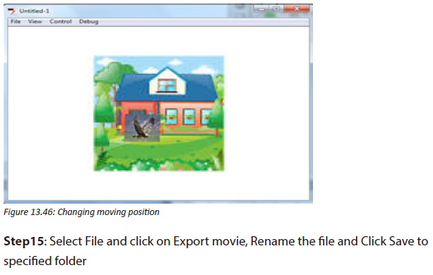
b. Deleting unwanted clip video
The universal character of AVS Video Converter is probably the main secret of its
popularity. This compact tool is ideal not only for converting files, it can also be
used for simple video editing and burning the resulting videos to discs.
The Edit function is the one that causes most of the problems as it implies working
with the timeline. The following guides will give some tips on editing video
with AVS Video Converter, in particular, on how to delete unnecessary parts from
files.
Step 1: Run AVS Video Converter and select your input video file
To select a video you would like to convert hit the Browse... button next to
the Input File Name field. In the opened Windows Explorer window browse for the
necessary video file:
Step 2: Switch to the Edit area
Once the input video is loaded, press the Edit button on the Main Toolbar to open
the Edit Input File(s) window.
The video file(s) you loaded into the software will be represented on the Timeline.
The following components will help navigate the video:
1. The Timeline Scale in the upper part of the Timeline shows the file in its
chronological sequence – in hh.mm.ss format. Use the Zoom slider on the
right to zoom in or zoom out the scale.
2. The Preview Area located in the right part of the Edit Input File(s) screen
allows you to visually control the editing process. The current position of
the cursor is always displayed in this area. By default it displays the very
first frame of the video you imported into the program.
Step 3: Delete a part of the video file: set start/end of the deletion area
Navigate the file (use the tips provided at Step 3) to find the initial moment
of the episode you wish to cut out. Left-click on the timeline to place a cursor,
Use playback controls located in the Preview Area, hotkeys or simply drag the
cursor to adjust its position. When ready, press Trim Start right above the timeline
to set the initial point of the area you wish to delete. Perform the same actions to
find the final point of the area you wish to delete. Press the Trim End button to set
a marker.
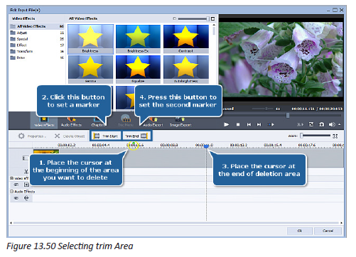
As soon as you set the second marker, a blue-colored area will appear in
the Deletions area highlighting the deleted part on the timeline.
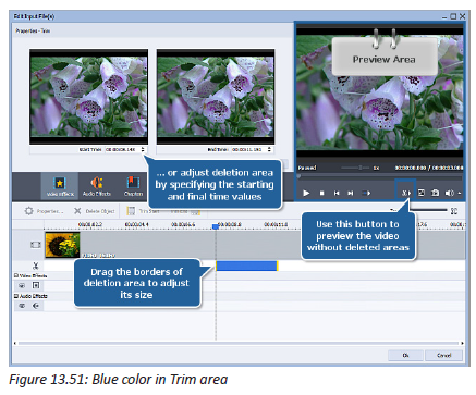
Note: you can add more than one area of deleting to your video just by going
through the same procedure once again. The active area of deletion is marked by
yellow stripes at the limits of the area.
Step 4: Delete a part of the video file: adjust the size of the selected area
You can change the size of the selected area for deletion by adjusting its borders.
To adjust the borders:
• Drag the borders of the area of deletion with the mouse.
• Adjust the borders in the Properties - Trim window. Double-click an area of
deletion to access this window. It will be displayed in the left part of the Edit
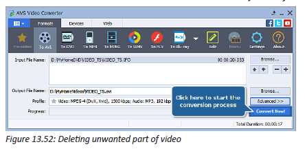
Input File(s) screen. The Properties - Trim screen contains 2 windows
which display the initial and final points of the area of deletion. Use the
arrows or enter the hh.mm.ss manually to adjust the borders of the area.
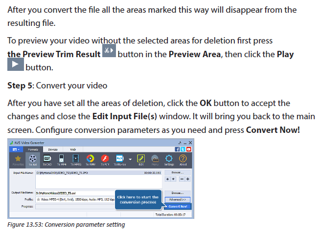
Wait while the software converts your video. It might take up to several hours
depending on your computer capabilities. The edited video of a new format is now
ready to be watched.
c. Add text with ms windows movie maker
MS Windows Movie Maker has always been one of the most popular software for
simple video editing. It can join video files, lets you add audio and music to your
video, apply video transitions, create slideshows and many more. The software is
pretty easy to use. Here is how to add captions to video in Movie Maker:
Step 1: Open Movie Maker and add the video clips;
Step 2: Then click on Home tab and choose Caption;
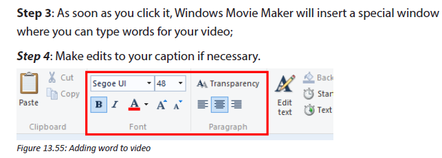
Step 5: Save your video track to apply changes.
It is a convenient and simple software that provides a multi-functional message
editor. You can change position, font and size. Moreover, you can choose the
transition effect to your wording and make it appear in an unusual way.
d. Morphing
Morphing is a special effect in motion pictures and animations that changes
(or morphs) one image or shape into another through a seamless transition. Most
often it is used to depict one person turning into another through technological
means or as part of a fantasy or surreal sequence.
In this practice, JockSource movie and Sheep source movie is going to be used
Begin by opening After Effects Software and importing the two Quicktime files:
Jock-Source.mov and Sheep-Source.mov.
Step1: In the project window, drag one of the footage items onto the composition
icon at the bottom of the window, so it creates a new composition at the same
size and frame rate as the source file. The composition should be 320 x 320, square
pixels at 25 fps.
Change the composition settings to have duration of six seconds, and then drag
the other footage file into the composition. Call it “Reshape-Morph project”
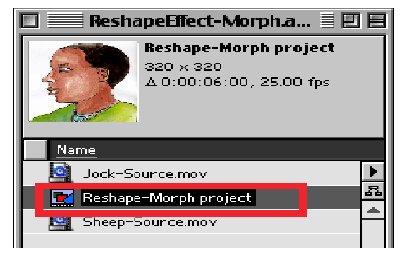
Figure 13.56: Importing image to be morphed
Step2: Arrange the footage items so that the bottom layer is Jock, beginning at
frame 0, and the top layer is the Sheep, starting at the three-second mark. There
should be a one-second overlap, which is where the effect will take place. To make
things simpler, split the Jock layer at the 3:00 point, then go to the four second
mark (4:00) and split the Sheep layer, so our effect can be applied to layers only
as long as it’s used. From this point on, when referred to the “Jock layer” and the
“Sheep layer” the one-second layers is referenced, and not the other, longer clips.
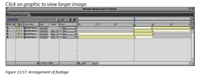
Step3: The first step in creating morph effect is to create a mask around the object.
Turn off the Sheep layer and go to the 3-second mark where the Jock layer begins.
If Jock layer is selected in the timeline, pressing “i” will take to the in-point. Using
the pen tool, draw a mask around Jock and make sure it is closed. It is easier to
draw a mask when the image is greyscale, so click on the green button at the
bottom of the composition window so the green channel will be appeared. It may
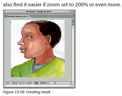
Step4: Because Jock moves during the one second, the shape is needed to be
animated to match the mask in his movement. Press “m” to reveal the mask
properties in the timeline window, and click on the stopwatch. This will add a
keyframe which records the shape of the mask at the 3:00 point.
It is important to note that only masks is needed to define the shapes which are
going to be morphed, there is no need masks which act as masks cut out the
background. So where it says “add”, select “none” from the mask menu to turn off
the mask, otherwise clip fine detail from the edge of Jock’s face. Clicking on the
name of the mask, which by default is “Mask 1” and then pressing “enter” will allow
to rename the mask to avoid confusion later, so call it “Jock shape”.

Step5: Press the “o” key to go to the out-point of the Jock layer, which is 3:24. Using
the selection tool, adjust the mask to match Jock’s position in this frame. He hasn’t
moved very much and it’s really only the profile of his face which needs to be
changed. After Effects will automatically add another keyframe for the new mask
shape, and it will animate the shape over time.
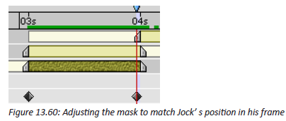
If the timeline is scrubbed, the mask animates over the one-second period, it
matches Jock pretty well. It is not necessary to adjust the mask any further.
Step6: The next step is to do the same thing for the Sheep layer. Draw a closed
mask around the Sheep, enable mask animation with a keyframe at 3:00 and then
move to 3:24 and adjust the mask to match.
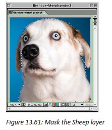
Unlike Jock, the mask with only two keyframes doesn’t fit the Sheep that accurately
as it animates, so at 3:10 and 3:20, tweak the shape of the mask to match the
Sheep’s movement. Rename the mask to “Sheep Shape” and ensure the mask mode
is “none” and not “add”.

Once masks are outline two subjects and animate over time to match their
movement, begin on the actual morph effect.
Step7: Copy and paste each mask onto the other layer, so that both layers have
both masks. Rename the layers once pasted them (they default back to “Mask 2”)
and turn them off by selecting “none” from the mask menu.
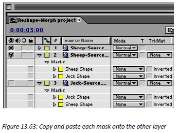
In the composition window, you should now see the shapes of the two masks
overlapping the footage items.

Turn off the visibility of the Sheep layer, select the Jock layer and apply the Reshape
effect from the “Distort menu”.
Step8: Change the defaults. Change the “source mask” to “Jock Shape”. This is the
starting point which is defining the parts of the image to be morphed.

Step9: Change the “destination mask” to “Sheep Shape” everything that is inside
the “Jock Shape” masks namely Jock to be wrapped into the shape defined by
the Sheep Shape mask. Change the boundary mask to “none” this can be used to
confine the area which is effected by the Reshape effect, but because the footage
is on a keyed unused background. If the Reshape effect is used on images which
are not keyed, add boundary mask to prevent the background from becoming
distorted by the Reshape effect.
Application Activity 13.6.
1. In computer lab, download adobe flash software, movie maker and
install it in your computer and do the following:
a. Use a smartphone/ digital camera to record a simple video
b. Import the recorded video and do all necessary operation to be an
audible or quality video.
c. Create animation from static object
d. Set different frames for creating Video clips
e. Delete unwanted clips
f. Create morphing
2. Make a movie where you show the life of students at your school
End unit assessment
Question 1:What are advantages and disadvantages of Multimedia?
Question 2: How many production teams are needed in Multimedia Production?
State them
Question 3: Download an image of a Sheep. Using multimedia editing software,
animate from frame o to 80 by drawing the line where it will pass through.
Question 4: How 2–D animations are classified?
Question 5: What are the uses of hyperlinks?
Question 6: What are the uses of Morphing and Warping?
UNIT 14: FILE HANDLING IN C++
Key unit competency
Open, close, create a data file in C++ and read, write and append data to Files
Introductory Activity
Observe the figure below and answer the following questions.
1. What do you understand by file?
2. Provide two examples of files.
3. How do we store files?
4. What do you understand by file size?
5. Create “BOOK.txt” file.
6. Put some text in the file created above
7. Write a function in C++ to count the number of uppercase alphabets
present in a text file “BOOK.txt”.
8. Write a function in C++ to count letters present in a text file “BOOK.txt”.
9. Write a function in C++ to count digits present in a text file “BOOK.txt”.
10. Write a function in C++ to count white spaces present in a text file
“BOOK.txt”
11. Write a function in C++ to count vowels present in a text file “BOOK.txt”.
14.1. Understanding files
Learning Activity 14.1.
1. Explain the types of files
2. Provide one example of each file type
3. Discuss the role of file name
4. Differenciate text file from binary files
Every program or sub-program consists of two major components: algorithm and
data structures.
The algorithm takes care of the rules and procedures required for solving the
problem and the data structures contain the data. The data is manipulated by the
procedures for achieving the goals of the program.
A data structure is volatile by nature in the sense that its contents are lost as soon
as the execution of the program is over. Similarly, an object also loses its states after
the program is over. To store permanently the data or to create persistent objects t
becomes necessary to store the same in a special data structure called file. The file
can be stored on a second storage media such as hard disk. In fact, vary large data is
always stored in a file.
14.1.1. File
A file is a self-contained piece of information available to the operating system and
any number of individual programs. A computer file can be thought of much like a
traditional file that one would find in an office’s file cabinet. Just like an office file,
information in a computer file could consist of basically anything.
Whatever program uses an individual file is responsible for understanding its
contents. Similar types of files are said to be of a common “format.” In most cases,
the easiest way to determine a file’s format is to look at the file’s extension.
Each individual file in Windows will also have a file attribute which sets a condition
to the specific file. For example, you can’t write new information to a file that has
the read-only attribute turned on.
A file name is just the name that a user or program gives the file to help identify what
it is. An image file may be named something (example of file name with extension:
kids-lake-2017.jpg). The name itself doesn’t affect the contents of the file, so even
if a video file is named something like image.mp4, it doesn’t mean it’s suddenly a
picture file.
Files in any operating system are stored on hard drives, optical drives, and other
storage devices. The specific way a file is stored and organized is referred to as a file
system.
Examples of Files:
An image copied from a camera to a computer may be in the JPG or TIF format.
These are files in the same way that videos in the MP4 format, or MP3 audio files, are
files. The same holds true for DOC/DOCX files used with Microsoft Word, TXT files
that hold plain text information, etc.
Though files are contained in folders for organization (like the photos in your Pictures
folder or music files in your iTunes folder), some files are in compressed folders, but
they’re still considered files. For example, a ZIP file is basically a folder that holds
other files and folders but it actually acts as a single file.
Another popular file type similar to ZIP is an ISO file, which is a representation of a
physical disc. It’s just a single file but it holds all the information found on a disc, like
a video game or movie.
From these few examples, it is clear that not all files are alike, but they all share a
similar purpose of holding information together in one place.
14.1.2. Types of files:
a. A. Binary Files
Binary files typically contain a sequence of bytes, or ordered groupings of eight bits.
When creating a custom file format for a program, a developer arranges these bytes
into a format that stores the necessary information for the application. Binary file
formats may include multiple types of data in the same file, such as image, video,
and audio data. This data can be interpreted by supporting programs, but will show
up as garbled text in a text editor. Below is an example of a .PNG image file opened
in an image viewer and a text editor.
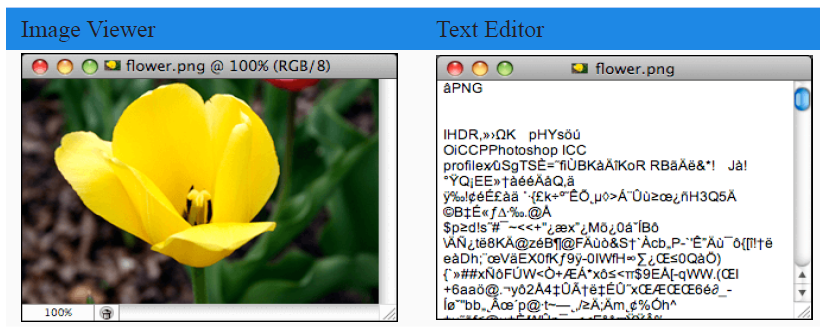
As it is seen, the image viewer recognizes the binary data and displays the
picture. When the image is opened in a text editor, the binary data is converted
to unrecognizable text. However, some of the text is readable. This is because the
PNG format includes small sections for storing textual data. The text editor, while
not designed to read this file format, still displays this text when the file is opened.
Many other binary file types include sections of readable text as well. Therefore, it
may be possible to find out some information about an unknown binary file type by
opening it in a text editor.
Binary files often contain headers, which are bytes of data at the beginning of a
file that identifies the file’s contents. Headers often include the file type and other
descriptive information. For example, in the image above, the “PNG” text indicates
the file is a PNG image. If a file has invalid header information, software programs
may not open the file or they may report that the file is corrupted.
b. Text Files
Text files are more restrictive than binary files since they can only contain textual
data. However, unlike binary files, they are less likely to become corrupted. While
a small error in a binary file may make it unreadable, a small error in a text file may
simply show up once the file has been opened. This is one of reasons Microsoft
switched to a compressed text-based XML format for the Office 2007 file types.
Text files may be saved in either a plain text (.TXT) format or rich text (.RTF) format. A
typical plain text file contains several lines of text that are each followed by an Endof-
Line (EOL) character. An End-of-File (EOF) marker is placed after the final character,
which signals the end of the file. Rich text files use a similar file structure, but may also
include text styles, such as bold and italics, as well as page formatting information.
Both plain text and rich text files include a (character encoding| character encoding)
scheme that determines how the characters are interpreted and what characters
can be displayed.
Since text files use a simple, standard format, many programs are capable of reading
and editing text files. Common text editors include Microsoft Notepad and WordPad,
which are bundled with Windows, and Apple TextEdit, which is included with Mac
OS X.
c. The difference between binary and text files
All files can be categorized into one of two file formats: binary or text. The two
file types may look the same on the surface, but they encode data differently. While
both binary and text files contain data stored as a series of bits (binary values of
1s and 0s), the bits in text files represent characters, while the bits in binary files
represent custom data.
While text files contain only textual data, binary files may contain both textual and
custom binary data.
Application Activity 14.1.
1. Discuss text files and provide two examples.
2. Describe binary files and provide two examples.
3. Explain the role of file extension
4. Where are files stored?
14.2. File Streams
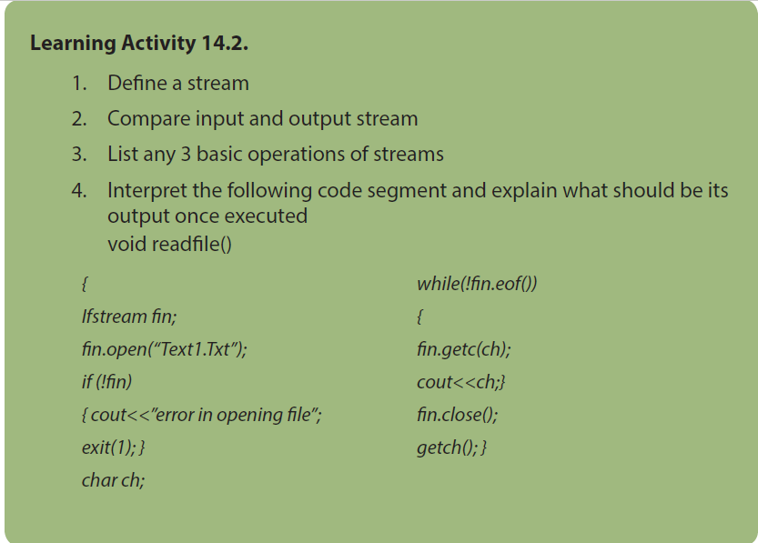

14.2.1. Introduction
One of the great strengths of C++ is its I/O system, IO Streams. As Bjarne Stroustrup
says in his book “The C++ Programming Language”, “Designing and implementing
a general input/output facility for a programming language is notoriously difficult”.
He did an excellent job, and the C++ IOstreams library is part of the reason for C++’s
success. IO streams provide an incredibly flexible yet simple way to design the input/
output routines of any application.
IOstreams can be used for a wide variety of data manipulations to the following
features:
A ‘stream’ is internally nothing but a series of characters. The characters may be either
normal characters (char) or wide characters (wchar_t). Streams provide users with a
universal character-based interface to any type of storage medium (for example,
a file), without requiring the to know the details of how to write to the storage
medium. Any object that can be written to one type of stream, can be written to all
types of streams. In other words, as long as an object has a stream representation,
any storage medium can accept objects with that stream representation.
Streams work with built-in data types, and the user can make user-defined types
work with streams by overloading the insertion operator (<<) to put objects into
streams, and the extraction operator (>>) to read objects from streams.
The stream library’s unified approach makes it very friendly to use. Using a consistent
interface for outputting to the screen and sending files over a network makes life
easier. The programs below will show what is possible.
14.2.2. Meaning of input and output
The input is whatever the user enters through a keyboard or any other input devices
while output what is written (displayed) on a output device being screen, printer
or file. The information input or output is considered as a stream of characters.
Suppose that the user enters the number 7479. The set of 4 characters: ‘7’, ‘4’, ‘7’ and
‘9’ taken as input can be considered as numbers or a string. the input characters
must be put into a recognizable data type for them to be of any use other than as a
character array.
IO streams not only define the relation between a stream of characters and the
standard data types but also allows the user to define a relationship between a
stream of characters and its classes. It also allows the user nearly limitless freedom
to manipulate those streams both using object oriented interfaces and working
directly on character buffers when necessary
14.2.3. Working with streams
Streams are serial interfaces to storage, buffers files, or any other storage medium.
The difference between storage media is intentionally hidden by the interface;
the usermay not even know what kind of storage he/she is working with but the
interface is exactly the same.
The “serial” nature of streams is a very important element of their interface. The
usercannot directly make random access: random reads or writes in a stream (unlike,
say, using an array index to access any wanted value) although he/she can seek to a
position in a stream and perform a read at that point.
Using a serial representation gives a consistent interface for all devices. Many devices
have the capability of both producing and consuming data at the same time; if data
is being continually produced, the simplest way to think about reading that data is
by doing a fetch of the next characters in a stream. If that data hasn’t been produced
yet (the user hasn’t typed anything, or the network is still busy processing a packet),
he/she waits for more data to become available, and the read will return that data.
Even if he/she tries to seek past the end (or beginning) of a stream, the stream
pointer (i.e. get or put pointer) will remain at the boundary, making the situation
safe. (Compare this with accessing data off the end of an array, where the behavior
is undefined.)
The underlying low-level interface that corresponds to the actual medium very
closely is a character buffer (the stream buffer, technically called the streambuf),
which can be thought of as the backbone of the stream. Being a buffer, it does not
hold the entire content of the stream, if the stream is large enough, so you can’t use
it for random access.
14.2.4. The most important of the basic stream operations are
First, the stream is initialized with the appropriate type (like a std::string for a
stringstream and the filename for an fstream) of values and suitable modes (like
ios::in for input and ios::out for output and many more depending on the type of the
stream).
After that, the user can specify where the I/O should occur, through the get and put
pointers. Depending on how the stream is opened, the location may already be set
appropriately (for example, if a file is opened with ios::app, the get pointer sets at the
end of the stream, allowing appends).
14.2.5. Functions of file stream classes
14.2.5.1. Introduction
In this brief introduction, the basic operations on both text and binary files are
discussed so that the functions to carry out these tasks are well understood.
The Basic File Operations on Text Files are:
• Creating an empty file – First time when a file is created with some valid
filename it is empty therefore it contains only EOF marker and a location
pointer pointing to it.
• Opening a file – A file is opened for reading/writing or manipulation of
data on it. If a file exists then only it can be opened , when a file is opened
the location pointer points to the Beginning of file.
• Closing a file – After the file operations done , the file should be closed. If
we don’t close the file it gets automatically closed when the program using
it comes to an end.
• Writing text into file – Once a file is created , data elements can be stored
to it permanently. The already existing contents are deleted if we try to
write data to it next time, rather we can append data to it and keep the
existing data.
• Reading of text from an already existing text file (accessing sequentially)
• Manipulation of text file from an already existing file – An existing file
is opened first and then the manipulation is done in sequential order. for
example – counting of words.
• Detecting EOF – When the data from the file is read in sequential order, the
location pointer will reach to the end of file. After reaching at the EOF no
attempt should be made to read data from the file.
• Copying of one text file to other text file
The Binary file operations are:
1. Creation of file – A binary file is always opened in binary mode for both
reading or writing. Upon successful creation, the pointer is set to the
beginning of the file.
2. Writing data into file – A binary file is opened in output mode for writing
data in it. A binary file contains non readable characters and write
function is used to write the records into file.
3. Searching for required data from file – a binary file is opened in input
mode for searching data. The file can be read sequentially one by one each
record or randomly by going to that particular location.
4. Appending data to a file – appending means addition of new records to
an already existing file.
5. Insertion of data in sorted file
6. Deletion of data
7. Modification/Updation of data
14.2.6. Components of c++ to be used with file handling
In C++ file input/output facilities are performed by a header file fstream.h, which
exists in the C++ standard library. C++ provides specific classes for dealing with user
defined streams. Every file in C++ is linked to a stream. A stream must be obtained
before opening a file. The file fstream.h is inherited from iostream.h, thus includes
all the classes included in iostream.h .
User defined streams – The four classes for file Input/Output are :
a. Ifstream – derived from istream and used for file input(reading). It inherits
the functions get(), getline() and read() and functions supporting random
access(seekg() and tellg() and >> operator. It also contains open(),close()
and eof().
b. ofstream – derived from ostream and used for file output(writing). It
inherits the functions put() and write() functions along with functions
supporting random access (seekp() and tellp() from ostream class. It also
contains open(),close() and eof().
c. fstream – derived form iostream and used for both input and output.
It inherits all the functions from istream and ostream classes through
iostream.h.
d. Filebuf – it sets the buffers to read and write and contains close() and
open() member functions in it.
14.2.7. Text File Operations
14.2.7.1. Reading Operation
a. Reading a File Character by character (including space,’\n’,’\t’)
Example:
Observe the following C++ program, interpret it and thereafter run it.
#include <iostream>
#include <fstream>
#include <string>
usingnamespace std;
int main () {
string line;
ifstream myfile (“example.txt”);
if (myfile.is_open())
{
while ( getline (myfile,line) )
{
cout << line <<’\n’;
}
myfile.close();
}
else cout <<”Unable to open file”;
return 0;
}
Explanations on how to write a program that reads from a file.
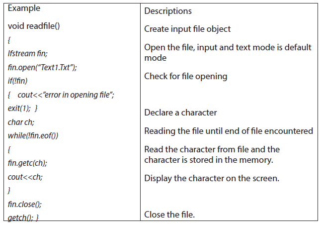
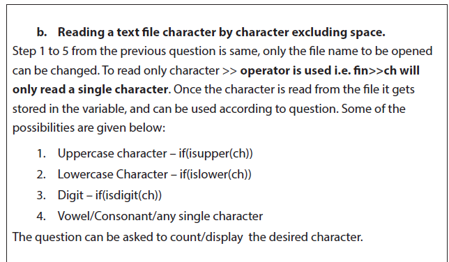
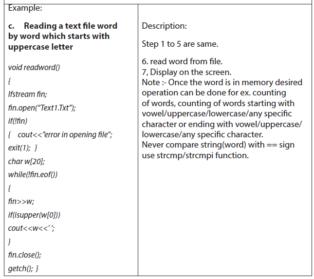
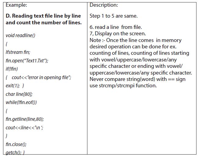
14.2.7.2. Writing in Text File
Example:
Observe the following C++ program, interpret it and thereafter run it:
#include <iostream>
#include <fstream>
usingnamespace std;
int main () {
ofstream myfile;
myfile.open (“example.txt”);
myfile <<”Writing this to a file.\n”;
myfile.close();
return 0;
}

Example:
Observe the following C++ program, interpret it and thereafter run it:
#include <iostream>
#include <fstream>
usingnamespace std;
int main () {
ofstream myfile (“example.txt”);
if (myfile.is_open())
{
myfile <<”This is a line.\n”;
myfile <<”This is another line.\n”;
myfile.close();
}
else cout <<”Unable to open file”;
return 0;
}
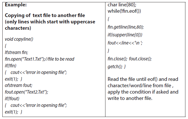
Binary Files are also called fixed length files or packed files as all the fields in a binary
file occupy fixed number of bytes.
For Opening files C++ provides mechanism for opening file in different modes:
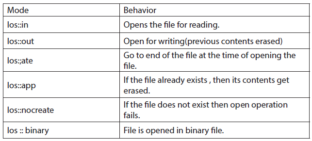
Note:
A file can be opened in more than one modes by making use of pipe sign as follows:
fstream file(“ABC”,ios::in|ios::binary|ios::out);
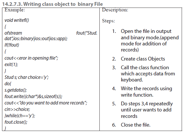
a. Writing class object to binary File (assuming student class ) and
function is a member function
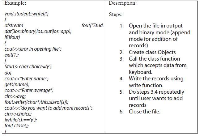
b. Writing Structure object to binary File (assuming student is structure,
containing name and avg as members)
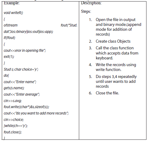
14.2.7.4. Reading a Binary File
Example:
Observe the following program, interpret it and run it:
#include <iostream>
#include <fstream>
usingnamespace std;
int main () {
streampos size;
char * memblock;
ifstream file (“example.bin”, ios::in|ios::binary|ios::ate);
if (file.is_open())
{
size = file.tellg();
memblock = newchar [size];
file.seekg (0, ios::beg);
file.read (memblock, size);
file.close();
cout <<”the entire file content is in memory”;
delete[] memblock;
}
else cout <<”Unable to open file”;
return 0;
}
a. Sequential reading
Sequential reading means reading record one by one until end of file and all the
records are displayed.
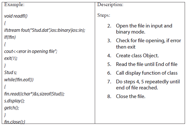
Displaying selected records -This is condition based display, where the condition
is checked after reading. If the reading is concerned with reading class objects then
there will be a function in class as a public member which will return that particular
value that is to be evaluated. If the structure instance is to be read from file then
the normal comparison can be done after executing the file read statement. If the
condition is true then call display function or display the record.
Display Records from file where average marks are greater than 60
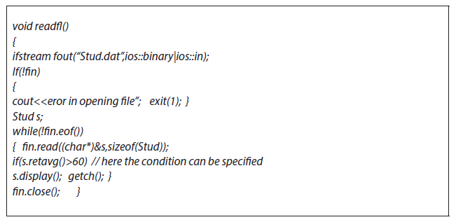
b. Random Access
Up till now we had been writing and reading the files in sequential manner but
binary files, being fixed length files, provides liberty to perform read and write
operations randomly. C++ provides functions for it. When you open a file operating
system assigns two exclusive pointers to file object. In C++ these pointers are called
get pointer(input) and put pointer(output) . These pointers provide you the facility
to move to the desired place in the file to perform read, write operations. The get
pointer specifies a location from where the current reading operation is initiated.
The put pointer specifies a location where the current write operation will take place.
14.2.7.5. Functions for manipulating file pointers
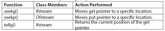
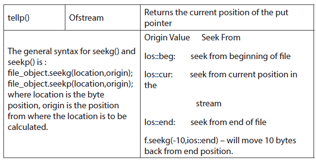
a. Random record reading
File pointer position is set according to the record number to be displayed. The file
pointer directly can be set to the position using seekg().
Note:- when file is opened in input or output mode the file pointer is at the starting
i.e. at 0 position. In append mode the file pointer is at the end of file, and the writing
continues by adding the records.
void readrec()
{
ifstreamfin(“stud.dat”,ios::binary|ios::in);
stud s;
int rec;
cout<<”enter the record you want to display”;
cin>>rec;
fin.seekg((rec-1)*sizeof(stud),ios::beg); // by default ios::beg is default argument
fin.read((char*)&s,sizeof(stud));
s.display();
getch();
}
b. Updation of record in existing file
In this the record to be updated is asked from the user, then appropriate position of
file pointer is obtained and pointer is set and writes operation is performed.
Eg.– writing a program to update structure/class object to update.
c. Insertion in Sorted file
The record to be inserted in a sorted file is accepted as a separate object. The file
in which the record is to be inserted, is opened in input mode. The records with
record key smaller than the record key to be inserted are copied to temporary file
and then record to be inserted is copied, following with rest of the records if any.
After that original file is removed using remove() and temporary file is renamed with
the original name with rename().
d. Deletion of record from file
The logic of deleting record is:
1. Accept the record key for the record you want to delete.
2. Read the file sequentially , from which the record is to be deleted and
copied down the records to temporary file except the record you want to
delete (by comparing the record value)
3. Remove the original file and rename the temporary file with the original
file name.
Sorting the records of an existing file - First the records in the file are counted . an
array of objects is created dynamically / statically with the approx. index value as
compared to number of records.
And read the file using the following statement:
while (fin.read(char*)&obj[i++],sizeof(class))); After reading the file , sort the array
with any sorting technique(Bubble/Insertion/Selection) Then write the sorted array
in to the file opened in output mode.
Notes:-
1. Multiple File Handling-
In this case the point to remember is:
a)Identify the file mode to be opened .
b) One object can open only one file at a time.
2. Sizeof() operator gives the sizeof data type.
3. The data written to a file using write() can only be read accurately using
read().
4. The files are closed using destructor of file object, if not closed using
close(). It is must to close the file. If the file pointer is opening another file
in the same program otherwise it is a good practice to use close().
Learning Activity 14.2.
1. Write a C++ program to open and read text from a text file character
by character in C++. We have a file named “test.txt”, this file contains
following text:
Hello friends, how are you?
I hope you are fine and learning well.
Thanks.
We will read text from the file character by character and display it on the output
screen.
2. Using C++, create a file and then write some text into that file, after
writing text file it will be closed and again file will open in read mode,
read all written text.
3. Provide a C++ program to write and read variable’s values in/from text
file. Here you will show how to write values in file and how to access
them.
4. Give a C++ program to write and read values through object in/from
text files. Demonstrate how to write object value in file and how to
access them.
5. The function tellg() and tellp() are predefined functions which tells
(returns) the position of the get and put pointers. Write a C++ program
to demonstrate example of tellg() and tellp() function.
14.2.7.6. Closing a file
a. Detecting the End of a File
The eof() member function reports when the end of a file has been encountered.
if (inFile.eof())
inFile.close();
A File is closed by disconnecting it with the stream it is associated with. The close
function is used to accomplish this task.
Syntax:
Stream_object.close
Example :
fout.close();
eof
This function determines the end-of-file by returning true (non-zero) for end of file
otherwise returning false(zero).
Syntax
Stream_object.eof
Example :
fout.eof
b. Testing for Open Errors
dataFile.open(“cust.dat”, ios::in);
if (!dataFile)
{
cout << “Error opening file.\n”;
}
Another way to Test for Open Errors
dataFile.open(“cust.dat”, ios::in);
if (dataFile.fail())
{
cout << “Error opening file.\n”;
}
Note on eof():
In C++, “end of file” doesn’t mean the program is at the last piece of information
in the file, but beyond it. The eof() function returns true when there is no more
information to be read.
Application activity 14.3.:
1. Write a C++ program that demonstrates the declaration of an fstream
object and the opening of a file.
2. Write a C++ program that demonstrates the opening of a file at the time
the file stream object is declared.
3. Write a C++ program that demonstrates the close function.
4. Write C++ program that uses the << operator to write information to a
file. The Program Screen Output will display:
File opened successfully.
Now writing information to the file.
Done.
And the Output to file demofile.txt will be:
Jones
Smith
Willis
Davis
5. This program writes information to a file, closes the file, then reopens it
and appends more information.
6. Write a program to create a binary file ‘student.dat’ using structure.
7. Program to read a binary file ‘student.dat’ display records on monitor.
8. Write the program that writes the information to a file, closes the file,
then reopens it and appends more information.
9. Provide a C++ program that will demonstrate how to write and read
time in/from binary file using fstream. Remember that there will be two
functions: writeTime() - that will write time into the file and readTime() -
that will read time from the file. In the program, there are two things to
be noticed, how time will be formatted into a string (using sprintf ) and
how time values will be extracted from the string (using sscanf ).
10. Write a C++ program to read an employee’s details from keyboard
using class and object then write that object into the file. The program
will also read the object and display employee’s record on the screen.
This program is using following file stream (file handling) functions.
There will be the following functions:
•• file_stream_object.open() to open a file
•• file_stream_object.close() to close the file
•• file_stream_object.write() to write an object into the file
•• file_stream_object.read() to read object from the file
In this program there are following details to be read through Employee class
•• Employee ID
•• Employee Name
•• Designation
•• Date of joining
•• Date of birth
Observe the program segment carefully and answer the question that follows:
class stock
{
int Ino, Qty; Char Item[20];
public:
void Enter() { cin>>Ino; gets(Item); cin>>Qty;}
void issue(int Q) { Qty+=0;}
void Purchase(int Q) {Qty-=Q;}
int GetIno() { return Ino;}
};
void PurchaseItem(int Pino, int PQty)
{ fstream File;
File.open(“stock.dat”, ios::binary|ios::in|ios::out);
Stock s;
int success=0;
while(success= = 0 && File.read((char *)&s,sizeof(s)))
{
If(Pino= = ss.GetIno())
{
s.Purchase(PQty);
_______________________ // statement 1
_______________________ // statement 2
Success++;
}
}
if (success = =1)
cout<< “Purchase Updated”<<endl;
else
cout<< “Wrong Item No”<<endl;
File.close() ;
}
a. Statement 1 to position the file pointer to the appropriate place so that
the data updating is done for the required item.
b. Statement 2 to perform write operation so that the updating is done in
the binary file.
1. Write C++ program that uses the file stream object’s eof() member
function to detect the end of the file.
Summary:
Let us talk briefly about some key concepts of file streams discussed here above:
filebuf
It sets the buffer to read and write, it contains close() and open() member functions
on it.
fstreambase
This is the base class for fstream and, ifstream and ofstream classes. therefore it
provides the
common function to these classes. It also contains open() and close() functions.
ifstream
Being input class it provides input operations it inherits the functions get
), read
and random access functions seekg
ofstream
Being output class it provides output operations it inherits put
access
functions seekp
fstream
It is an I/O class stream, it provides simultaneous input and output operations.
File modes
Meaning of file mode:
The file mode describes how a file is to be used ; to read from it, write to it, to append
and so on
Syntax
Stream_object.open(“filename”,mode);
File Modes are briefly discussed here below:
ios::out: It open file in output mode (i.e write mode) and place the file pointer in
beginning, if
file already exist it will overwrite the file.
ios::in: It open file in input mode (read mode) and permit reading from the file.
ios::app: It open the file in write mode, and place file pointer at the end of file i.e to
add new
contents and retains previous contents. If file does not exist it will create a new file.
ios::ate: It open the file in write or read mode, and place file pointer at the end of
file i.e input/
output operations can performed anywhere in the file.
ios::trunc: It truncates the existing file (empties the file).
ios::nocreate: If file does not exist this file mode ensures that no file is created and
open() fails.
ios::noreplace If file does not exist, a new file gets created but if the file already
exists, the
open() fails.
ios::binary Opens a file in binary mode.
Logic to read a text file:
• 1. Open file in read/input mode using std::in
• 2. Check file exists or not, if it does not exist terminate the program
• 3. If file exist, run a loop until EOF (end of file) not found
• 4. Read a single character using cin in a temporary variable
• 5. And print it on the output screen
• 6. Close the file
End unit assessment
1. Write a function in C++ to search for details (Phoneno and Calls) of those
Phones which have more than 800 calls from binary file “phones.dat”.
Assuming that this binary file contains records/ objects of class Phone,
which is defined below.
class Phone
{
Char Phoneno[10]; int Calls;
public:
void Get() {gets(Phoneno); cin>>Calls;}
void Billing() { cout<<Phoneno<< “#”<<Calls<<endl;}
int GetCalls() {return Calls;}
};
2. Write a function in C++ to add new objects at the bottom of a binary file
“STUDENT.DAT”, assuming the binary file is containing the objects of the
following class:
class STUD
{
int Rno;
char Name[20];
public:
void Enter()
{cin>>Rno;gets(Name);}
void Display(){cout<<Rno<<Name<<endl;}
};
3. Given a binary file PHONE.DAT, containing records of the following class
type
class Phonlist
{
char name[20];
char address[30];
char areacode[5];
char Phoneno[15];
public:
void Register()
void Show();
void CheckCode(char AC[])
{return(strcmp(areacode,AC);
};
Write a function TRANSFER
having areacode as “DEL” from PHONE.DAT to PHONBACK.DAT.
4. Given a binary file SPORTS.DAT,containg records of the following structure
type:
struct Sports
{
char Event[20] ; char Participant[10][30] ;
} ;
Write a function in C++ that would read contents from the file SPORTS.DAT and
creates a file named ATHLETIC.DAT copying only those records from SPORTS.DAT
where the event name is “Athletics”.
5. 5.Given a binary file TELEPHON.DAT, containing records of the following
class Directory :
class Directory { char Name[20] ; char Address[30] ;
char AreaCode[5] ; char phone_No[15] ; public ;
void Register
int CheckCode(char AC[ ])
{ return strcmp(AreaCode, AC) ;
}
} ;
Write a function COPYABC
AreaCode as “123” from TELEPHON.DAT to
TELEBACK.DAT.
BIBLIOGRAPHY
1. National Curriculum Development Centre(NCDC). (2011). ICT Syllabus for
Upper Secondary. Kigali.
2. applications, D. M., Tumkur, S. I., & Bangalore., V. B.-P. (n.d.). Visual Basic 6.0
A simple Approach . 3rd Main Road, Gandhinagar, Bangalore- 5600 009:
Sapna Book House.
3. Byron S. GOTTFRIED, P. (n.d.). schaum’s ouTlines Visual Basic.
4. Chopra, R. (2009). OPERATING SYSTEM (A PRACTICAL APP). New Delhi: S
Chand & Company Pvt Ltd.
5. Dhamdhere, D. (2006). OPERATING SYSTEMS: A CONCEPT- BASED
APPROACH, 2E. New Delhi: Tata McGraw Hill Publishing Company Limited.
6. Dhotre, I. A. (2009). OPERATING SYSTEMS. New Delhi: Technical
Publications Pune.
7. Garrido, Schlesinger, Hoganson. (2013). MODERN OPERATING SYSTEMS
2ND EDITION. USA: Library of Congress Cataloging in Publication Data.
8. Godbole. (2011). OPERATING SYSTEM 3E. New Delhi: Tata McGraw Hill
Education Private Limited.
9. Haggard, G., & Shibata, w. H. (2013). Introduction: Visual Basic6.0.
bookboon.com.
10. Halvorson, M. (1999). Learn Microsoft Visual Basic 6.0 Now.
11. Khurana, R. (2011). OPERATING SYSTEMS (FOR ANNA). New Delhi: Vikas
Publishing Pvt Ltd.
12. McGrath, M. (2008). Visual Basic in Easy Steps.
13. MINEDUC. (2008). Geographic and Information Systems(GIS). Kigali.
14. MINEDUC. (2013). Education Sector Strategic Plan . Kigali.
15. MINEDUC. (2014). ICT in Education Policy. Kigali: MINEDUC.
16. Ministry of Education, Sengapore,2007. (2007). Computer Applications
Syllabus(Lower Secondary Technical). Sengapore: Curriculum Planning&
Development Division.
17. MYICT. (2011). National ICT strategy and plan NICI III-2015.Kigali.
18. National Curriculum Development Centre(NCDC). (2006). ICT syllabus for
Lower Secondary Education. Kigali.
19. Norton, P. (1998). Guide to Visual Basic 6.0.
20. Pearson Education. (2010). Computer Concepts.
21. Sharma, Varshney, Shantanu. (2010). DESIGN AND IMPLEMENTATION OF
OPERATING SYSTEM. New Delhi: University Science Press.
22. University, M. (n.d.). Project NameSystem User Requirements. Project
NameSystem User Requirements; Projects Office.
23. University, O. S. (2018). Single Processor Scheduling Algorithms. Retrieved
March Tuesday, 2018, from Department of Computer Science and
Engineering: http://web.cse.ohio-state.edu/~agrawal.28/660/Slides/jan18.
pdf