General
- Physics SME Y3 TG File Uploaded 1/11/21, 16:40
UNIT 3: APPLICATIONS OF OPTICAL FIBER IN COMMUNICATION SYSTEM
Key Unit Competence:
Evaluate the application of optical fiber transmission and other transmittingsystems
Introductory activity
Investigating the use of optical fiber in RWANDA
Rwandan government has started connecting three million people to the
World Wide Web as part of the “Internet for All” project. The project is a World
Economic Forum initiative that aims to connect 25 million new Internet users in
Kenya, Uganda, South Sudan and Rwanda at the beginning of 2019.
This goal will partly be achieved by addressing the challenges of affordability,
digital skills gap, lack of local content and limited infrastructure, which arehindering growth in the use of Internet across the region
By using the information provided above, answer to the following questions:
1. Observe the images A, B and C of the figure .3.1 and describe each
one.
2. What do you think are the uses of the materials shown in the figure
above?
3. By using scientific ideas, explain why one may opt to use the method(s)
indicated in the figure above over another.
4. Can you highlight some of the disadvantages of the method of signaltransmission shown in the figure above?
3.1. OPTICAL FIBRE
Activity 3.1
Investigating the types of optical fiber.
a) Use search on internet or in library, discuss different types of optical
fiber.b) Differentiate them according to their respective uses.
3.1.1 Concept of optical fiber
An optical fiber (fiber optics) is a medium for carrying information from one point
to another in the form of light. It uses a flexible, transparent fiber made by drawing
glass or plastic and has a diameter slightly thicker than that of a human hair. They
are arranged in bundles called optical cables and can be used to transmit signals
over long distances.
An optical fiber is a cylindrical dielectric waveguide (non conducting waveguide)
made of low loss material that transmits light along its axis, by the process of total
internal reflection. The fiber consists of a core surrounded by a cladding layer, both
of which are made of dielectric materials.
The Fiber optic cable is made of high-quality extruded glass (si) or plastic, and it is
flexible. The diameter of the fiber optic cable is in between 0.25 to 0.5 mm (slightly
thicker than a human hair). Fiber optics continues to be used in more and moreapplications due to its inherent advantages over copper conductors.
An optical fiber essentially consists of three layers Core,Cladding and Buffer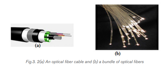
coating. The rest of the layers are provided in order to increase the flexibility,strength and protection from external stresses.
• Core:
Core is a thin glass/silica at the center of the optical fiber through which light
travels. A Glass material with high refractive index is used for this purpose. The core
of a fiber cable is a cylinder of plastic that runs all along the fiber cable’s length, and
offers protection by cladding. The diameter of the core depends on the application
used. Due to internal reflection, the light travelling within the core reflects from the
core, the cladding boundary. The core cross section needs to be a circular one formost of the applications.
• Cladding:
Core is surrounded by a medium, with lesser refractive index. Ray of light incident
on the core-cladding interface is reflected back into the core. Cladding ensures
that no light signal escapes from the optical fiber. Cladding is an outer optical
material that protects the core. The main function of the cladding is that it reflects
the light back into the core. When light enters through the core (dense material)
into the cladding (less dense material), it changes its angle, and then reflects backto the core.
• Coating:
The coating is the first non-optical layer around the cladding. The coating typically
consists of one or more layers of polymer that protect the silica structure againstphysical or environmental damage.
. Buffer Coating (Strength member)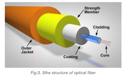
The entire structure is protected by a plastic coating. It is composed of multiple
layers and materials in order to protect from external shocks, moisture, surrounding
materials etc. The main function of the buffer is to protect the fiber from damage and
thousands of optical fibers arranged in hundreds of optical cables. These bundlesare protected by the cable’s outer covering that is called jacket.
• Outer Jacket
Fiber optic cable’s jackets are available in different colors that can easily make us
recognize the exact color of the cable we are dealing with. The color yellow clearly
signifies a single mode cable, and orange color indicates multimode.
The light is guided down the core of the fiber by the optical cladding which has a
lower refractive index. Remember that the refractive index is the ratio of the velocity
of light in a vacuum to its velocity in a specified medium. Then light is trapped in the
core through total internal reflection. The other outer parts that are the strength
member and the outer jacket, serve as protectors.
Connecting two optical fibers is done by fusion splicing or mechanical splicing.
It requires special skills and interconnection technology due to the microscopicprecision required to align the fiber cores.
3.1.2 Types of optical fiber
The properties of data transmission via a fiber optic depend on the core. Hence,
based on the differences in the structure of the core, there are three main types ofoptical fibers:
a. Single mode (monomode) fiber
To understand the behavior of electromagnetic waves in waveguides we use a
theory known as mode theory. The mode theory (this is a bit of an oversimplification)
essentially classifies electromagnetic waves on the basis of wavelengths into
different modes. A mode is a stable propagation state (stable operating points or
standing waves) in optical fibers.
Single-Mode Fibers: is a single stand of glass fiber with a diameter of 8.3 µm
to10 µm that has one mode of transmission. Single mode fibers are used to transmit
one signal per fiber; these fibers are used in telephone and television sets. Singlemode fibers have small cores.
As the name suggests, this type of optical fiber transmits only one mode of the light.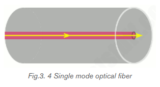
To put it another way, it can carry only one wavelength of light across its length.
This wavelength is usually 1310 nm or 1550 nm. Major reasons for this situationare as follows:
• The single mode optical fibers are much better than multimode optical
fibers as they have more bandwidth and experience fewer losses of the fiber
transmission. So the speed is unmatched.
• Interestingly, single mode fibers came into existence after multimode fibers.
They are more recent than the multimode cables.
• These cables can carry only one mode, physically, by having a tiny core. That
is to say that the diameter of the core is essentially of the same order as the
wavelength of the light passing through it.
• Only lasers are used as a light source. To point out, the light used in single
mode fibers are not in the visible spectrum.
• Since the light travels in a straight direction, there are fewer losses, and it can
be used in applications requiring longer distance connections.
• An obvious disadvantage of single mode fiber is that they are hard to couple.
• They have a superior transmission quality over other ber types because of
the absence of modal noise.
3.1.3 Multimode optical fiber
Multimode fibers are used to transmit many signals per fiber; these signals are usedin computer and local area networks that have larger cores.
• As the name implies, these types of optical fibers allow multiple modes of
light to travel along their axis.
• To explain physically, they can do this by having a thicker core diameter.
• The wavelengths of light waves in multimode fibers are in the visible spectrum
ranging from 850 to 1300 nm.
• The reflection of the waves inside the multimode fiber occurs at different
angles for every mode. Consequently, based on these angles the number of
reflections can vary.
• We can have a mode where the light passes without striking the core at all.
• We can have a slightly higher mode which will travel with appropriate internal
reflections.
• Since the basis of optical fiber communication is a total internal reflection,
all modes with incident angles that do not cause total internal reflection get
absorbed by the cladding. As a result, losses are created.
• We can have higher order modes, waves that are highly transverse to the axis
of the waveguide can reflect many times. In fact, due to increased reflections
at unusual angles, higher order modes can get completely lost inside the
cable.
• Lower order modes are moderately transverse or even completely straight
and hence fare better comparatively.
• There are two types of multimode optical fibers: stepped index and gradedindex.
a. Stepped index
In step-index multimode type, the core has the relatively large diameter of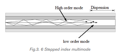
50 μm and the refractive index of the core is uniform throughout and undergoes an
abrupt change (or step) at the cladding boundary.
The wide core allows the infrared to travel by several paths or modes. Paths that
cross the core more often are longer, and signals in those modes are take longer to
travel along the fiber. Arrival times at the receiver are therefore different for radiation
of the same pulse, 30 ns km-1, being a typical difference. The pulse is said to suffer
dispersion, it means that it is spread out.
b. Graded-index multimode fiber
The core refractive index is made to vary as a function of the radial distance from
the center of the fiber.
If you look at the figure of stepped and graded index multimode fibers shown above,
you will notice that the waves in stepped index fiber arrive at the same point at
different times. This is because multiple modes have different velocities. As a result,
outputs are out of sync, and this reduces bandwidth. This is called intermodal
dispersion/distortion. However, this issue can be mitigated by using graded index
fibers. Since the refractive index changes radially the higher order modes are benttowards the lower order modes and as a result, they are synchronized in time.
In the graded index multimode type, the refractive index of the glass varies
continuously from a higher value at the center of the fiber to a low value at the
outside, so making the boundary between core and the cladding indistinct.
Radiation following a longer path, travel faster on average, since the speed of light
is inversely proportional to the refractive index. The arrival times for different modes
are the about the same (to within 1ns km-1) and all arrive more or less together at
the receiving end. Dispersion is thereby much reduced.
3.1.4 Micro structured optical fibers
These are the new types of optical fiber cables. In ordinary optical fibers mentioned
above, light travels due to total internal reflection and refractive indices of the
core and cladding. In micro structured optical fibers, the physical structure of the
waveguide is used at a nano-scale level to manipulate light.
Different types of micro structured optical fibers are constructed with a non
cylindrical core and/or cladding layer, usually with an elliptical or rectangular cross section.
These include:
• Polarization-maintaining fiber is a unique type of fiber that is commonly used
in fiber optic sensors due to its ability to maintain the polarization of the light
inserted into it.
• Photonic-crystal fiber is made with a regular pattern of index variation. It is
often in the form of cylindrical holes that run along the length of the fiber.
Such fiber uses diffraction effects instead of or in addition to total internal
reflection, to confine light to the fiber›s core.
• Air-clad or double clad fibers• Fresnel fibers
Application activity 3.1
1. Fiber optics is best known for its application in long-distance
telecommunications.
A. True
B. False
2. Choose the basic types of optical fiber:
A. Single-mode E. Multi-mode
B. X-mode F. A and C
C. Microwave-mode G. B and D
D. Graded-index mode H. A and E
3. Single-mode fiber has the advantage of greater bandwidth capability.
It has the disadvantage of:
A. Being harder to bend
B. Smaller mechanical tolerances in connectors and splices
C. Being difficult to couple light into
D. B and C
E. None of the above
4. Describe with the aid of simple ray diagrams:
A. The multimode step index fiber;
B. The single-mode step index fiber.
C. Compare the advantages and disadvantages of these two types of
fiber for use as an optical channel.5. Match the words of column A to their meaning of column B

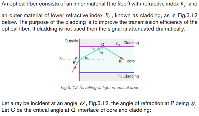
3.2 PRINCIPLE OF OPERATION OF OPTICAL FIBRES
Activity 3.2
Given the illustration above, one can see different rays inside the optical fiber.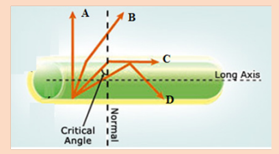
As the angle of incidence in the core increases, the angle of refraction increasesmore until it becomes right angle.
Discuss:
1. Name the rays A, B, C and D
2. As observed from the diagram, comment on the cause of different
directions of these rays.
3. Explain the scientific name of the angle for ray C to be in the direction
indicated in the figure.
4. Explain the scientific phenomenon represented by ray D.5. Explain any fields where the phenomenon stated in 4) above is applied.
3.2.1 Refractive index of light
When light fall at the interface (boundary) of two media, it is partially reflected andpartially refracted. As it passes from one medium to another it changes its direction.
The change in its direction is associated with the change in velocity. The ratio of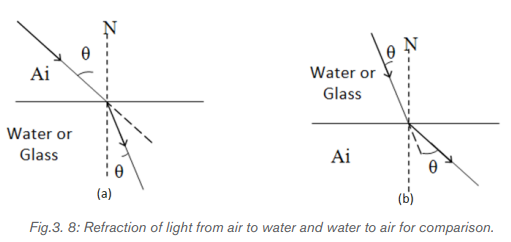
the speed of light in the vacuum c (or air) and that of light in a certain medium v iscalled the absolute refractive index n.
3.2.2 Total internal reflection
When light passes from one a medium of higher index of refraction into a medium
of lower refractive index the light bends away from the normal as indicated on
Fig.3.9. A weak internally reflected ray is also formed and its intensity increases asthe incident angle increases.
Increasing the angle of incidence increases the angle of refraction and at a particular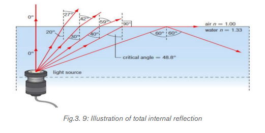
incidence, the angle of refraction reaches the 90°. This particular incident angle is
called the critical angle θ c . As the incident angle exceeds the critical angle, the
incident beam reflects on the interface between the 2 media and return in the first
medium. This effect is called total internal reflection.
For any two media, using Snell’s law the critical angle is calculated using theexpression
One of the applications of total internal reflection is optical fiber. An optical fiber is
basically made of 2 types of glass put together in a concentric arrangement so the
middle is hollow. The inner circle of glass also called the Core consists of a glass
of higher refractive index than the outside layer as indicated on Fig.3.10.
The outer layer of glass, which is also known as the optical cladding, does notcarry light but is essential to maintain the critical angle of the inner glass.
The underlying main physics concept behind the functioning of an optical fiber is a
phenomenon known as total internal reflection. Any light entering the fiber will
meet the cladding at an angle greater than the critical angle. If light meets the inner
surface of the cladding or the core - cladding interface at greater than or equal to
critical angle then total internal reflection (TIR) occurs. So, all the energy in the ray
of light is reflected back into the core and none escapes into the cladding. The ray
then crosses to the other side of the core and, because the fiber is more or less
straight, the ray will meet the cladding on the other side at an angle which again
causes the total internal reflection. The ray is then reflected back across the core
again and again until it reaches the end of the optical fiber.
A single optical fiber utilizes total internal reflection to transmit light, allowing bends
along its path. Minimal light loss during transmission allows optical fibers to transmit
light or data quickly over long distances. When bundled, fiberoptics can transmitlarge quantities of data for telecommunication applications.
Optical fibers use multiple total internal reflections to transmit light. They allow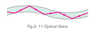
signals to travel for long distances without repeaters, which are needed to
compensate for reductions in signal strength. Fiber-optic repeaters are currently
about 100 km apart, compared to about 1.5 km for electrical systems.
Various consequences of Snell’s Law include the fact that for light rays traveling from
a material with a high index of refraction to a material with a low index of refraction,
it is possible for the interaction with the interface to result in zero transmission.
This phenomenon is called total internal reflection. As light signals travel down
a fiber optic cable, it undergoes total internal reflection allowing for essentially no
light lost over the length of the cable.Maximum angle of incidence
This the maximum angle of incidence in air for which all the light is total reflected
at the core-cladding.
This shows that there is a maximum angle of acceptance cone outside of which
entering rays will not be totally reflected within the fiber. For the largest acceptance
cone, it is desirable to choose the index of refraction of the cladding to be as small
as possible. This is achieved if there is no cladding at all. However, this leads to
other problems associated with the loss of intensity.
The transmission is reduced due to multiple reflections and the absorption of thefiber core material due to impurities.
Application activity 3.2
1. Operation of optical fiber is based on:
A. Total internal reflection D. Einstein’s theory of reality
B. Total internal refraction E. None of the above
C. Snell’s law
2. When a beam of light passes through an optical fiber
A. Rays are continually reflected at the outside(cladding) of the fiber
B. Some of the rays are refracted from the core to the cladding
C. The bright beam coming out of the fiber is due to the high refractive
index of the core
C. The bright beam coming out of the fiber is due to the total internal
reflection at the core-cladding interface
E. All the rays of light entering the fiber are totally reflected even at verysmall angles of incidence
3. A laser is used for sending a signal along a mono mode fiber because
A. The light produced is faster than from any other source of light
B. The laser has a very narrow band of wavelengths
C. The core has a low refractive index to laser light
D. The signal is clearer if the cladding has a high refractive index
E. The electrical signal can be transferred quickly using a laser
4. Given that the refractive indices of air and water are 1 and 1.33
respectively, find the critical angle.
5. A beam of light is propagating through diamond, n = 2.42 and strikes
a diamond-air interface at an angle of incidence of 28°.
a) Will part of the beam enter the air or will the beam be totally refracted at
the interface?
b) Repeat part (a) assuming that diamond is surrounded by water, n = 1.336. A beam of light passes from water into polyethylene (n = 1.5). If the
7. (a) What is the critical angle when light is going from a diamond
(n = 2.42) to air?
(b) Using the answer to (a), what happens when:
i) The angle of incidence is less than that angle?ii) The angle of incidence is more than that angle?
3.3. MECHANISM OF ATTENUATION AND LIGHT SCATTERING
Activity 3.3
The image above is a section of optical fiber. Imagining that it is transmitting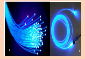
signal over a long distance,
a) Do you think all the fed signal can reach the destination? Defend your
reasoning.
b) If no, what do you think causes the loss in the signal transmission?
c) Suggest measures that should be done to minimize the energy lossduring transmission.
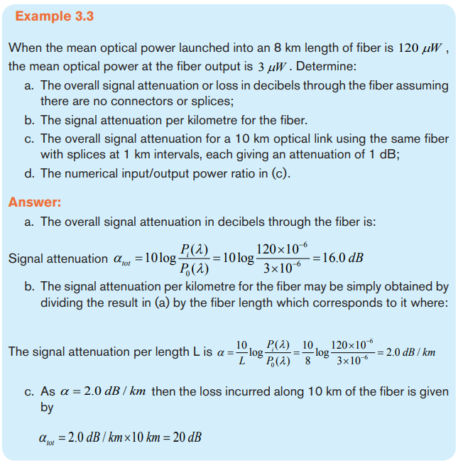
3.3.1 Mechanism of attenuation
Attenuation in fiber optics, also known as transmission loss, is the reduction in
intensity of the light beam (or signal) as it travels through the transmission medium.
Over a set distance, fiber optic with a lower attenuation will allow more power to
reach its receiver than a fiber with higher attenuation.
Attenuation can be caused by several factors both extrinsic and intrinsic:
• Intrinsic attenuation is due to something inherent to the fiber such as impurities
in the glass during manufacturing. The interaction of such impurities with light
results in the scattering of light or its absorption.
• Extrinsic attenuation can be caused by microbending and microbending. A
bent imposed on an optical fiber produce a strain in that region of the fiber
and affects its refractive index and the critical angle of the light ray in that
area. Microbending that is a large-scale bent and microbending which is
a small-scale bent and very localized are external causes that result in thereduction of optical power.
Attenuation coefficients in fiber optics usually are expressed decibels per kilometer
(dB/km) through the medium due to the relatively high quality of transparency ofmodern optical transmission media. It is observed that the attenuation is a function
Attenuation is an important limiting factor in the transmission of a digital signal across
large distances. Thus, much research has gone into both limiting the attenuationand maximizing the amplification of the optical signal.

3.3.2 Light scattering and absorption
In the light transmission of signals through optical fibers, attenuation occurs due to
light scattering and absorption of specific wavelengths, in a manner similar to thatresponsible for the appearance of color.
a. Light scattering
The propagation of light through the core of an optical fiber is based on total internal
reflection of the light wave. Rough and irregular surfaces, even at the molecular
level, can cause light rays to be reflected in random directions as it is illustrated on
Fig.3.14. This is called diffuse reflection or scattering, and it is typically characterized
by wide variety of reflection angles.
Light scattering depends on the wavelength of the light being scattered. Thus, limits
to spatial scales of visibility arise, depending on the frequency of the incident light
wave and the physical dimension (or spatial scale) of the scattering center, which is
typically in the form of some specific micro-structural feature. Since visible light has
a wavelength of the order of one micrometer (one millionth of a meter) scattering
centers will have dimensions on a similar spatial scale. Thus, attenuation resultsfrom the incoherent scattering of light at internal surfaces and interfaces.
b. Light absorption
Material absorption is a loss mechanism related to the material composition and
fiber fabrication process. This results in the dissipation of some transmitted optical
power as heat in the waveguide. Absorption is classified into two basic categories:
Intrinsic and extrinsic absorptions. (John, 2009)
• Intrinsic absorption: is caused by basic fiber material properties. If an optical
fiber is absolutely pure, with no imperfections or impurities, ten all absorption
will be intrinsic. Intrinsic absorption in the ultraviolet region is caused bands.
Intrinsic absorption occurs when a light particle (photon) interacts with an
electron and excites it to a higher energy level.
• Extrinsic absorption is caused by impurities caused by impurities introduced
into the fiber material. The metal impurities such as iron, nickel and chromium
are introduced into the fiber during fabrication. Extrinsic absorption is caused
by electronic transition of these metal ions from one energy level to another
level.
3.3.3 Measures to avoid Attenuation
The transmission distance of a fiber-optic communication system has traditionally
been limited by fiber attenuation and by fiber distortion.
• Repeaters: Repeaters convert the signal into an electrical signal, and then
use a transmitter to send the signal again at a higher intensity than was
received, thus counteracting the loss incurred in the previous segment. They
mostly used to be installed about once every 20 km.
• Regenerators: Optical fibers link, in common with any line communication
system, have a requirement for both jointing and termination of the
transmission medium. When a communications link must span at a larger
distance than existing fiber-optic technology is capable of, the signal must
be regenerated at intermediate points in the link by optical communications
repeaters called regenerators. An optical regenerator consists of optical
fibers with special coating (doping). The doped portion is pumped with a
laser. When the degraded signal comes into the doped coating, the energy
from the laser allows the doped molecules to become lasers themselves.
The doped molecules then emit a new strong light signal with the same
characteristics as the incoming weak signal. Basically, the regenerator is a
laser amplifier for the incoming signal.
• Optical Amplifiers: Another approach is to use an optical amplifier which
amplifies the optical signal directly without having to convert the signal into
the electrical domain. It is made by doping a length of fiber with the rare
earth mineral erbium and pumping it with light from a laser with a shorter
wavelength than the communications signal (typically 980 nm). Amplifiershave largely replaced repeaters in new installations.
Application activity 3.3
1. For each of the statements below, indicate true if it is correct and
false if it is wrong
A. One of the reasons fiber optics hasn’t been used in more areas has
been the improvement in copper cable such as twisted pair.
B. With current long-distance fiber optic systems using wavelength-division
multiplexing, the use of fiber amplifiers has become almost mandatory.
C. Fiber optics has extraordinary opportunities for future applications
because of its immense bandwidth.
2. (a) What do we mean by attenuation in optical fibers?
(b) State two ways in which energy is lost in optical fibers.
(c) If a fiber loses 5% of its signal strength per kilometer, how much ofits strength would be left after 20 km?
3.4 OPTICAL FIBRE COMMUNICATION
Activity 3.4
With the basic information you know about the functioning process of optical
fiber, answer to the following questions:
1. Where does the light that is transmitted into the optical fiber core
medium come from?
2. What are the type compositions of the light signal propagating into
optical fiber?
3. Discuss and explain the function principle of signal generators andsignal receivers of light from optical fibers.
3.4.1 Basic Fiber Optic Communication System
Even without defining information formally, we intuitively understand that speech,
audio, and video signals contain information. We use the term message signals for
such signals, since these are the messages we wish to convey over a communication
system. In their original form both during generation and consumption these message
signals are analog: they are continuous time signals, with the signal values also
Iying in a continuum. When someone plays the violin, an analog acoustic signal
is generated (often translated to an analog electrical signal using a microphone).
Even when this music is recorded onto a digital storage medium such as a CD
(using the digital communication), when we ultimately listen to the CD being played
on an audio system, we hear an analog acoustic signal. The transmitted signals
corresponding to physical communication media are also analog. For example,
in both wireless and optical communication, we employ electromagnetic waves,
which correspond to continuous time electric and magnetic fields taking values in
a continuum.
In all of these instances, the key steps in the operation of a communication link are
as follows:
a. insertion of information into a signal, termed the transmitted signal,
compatible with the physical medium of interest;
b. propagation of the signal through the physical medium (termed the channel)
in space or time;
c. Extraction of information from the signal (termed the received signal)
obtained after propagation through the medium.
For gigabits and beyond gigabits transmission of data, the fiber optic communication
is the ideal choice. This type of communication is used to transmit voice, video,
telemetry and data over long distances and local area networks or computer
networks. A Fiber Optic Communication System uses light wave technology to
transmit the data over a fiber by changing electronic signals into light.
Some exceptional characteristic features of this type of communication system like
large bandwidth, smaller diameter, light weight, long distance signal transmission,
low attenuation, transmission security, and so on make this communication a major
building block in any telecommunication infrastructure. The subsequent information
on fiber optic communication system highlights its characteristic features, basic
elements and other details.
3.4.2 Block diagram of Fiber Optic Communication
Unlike copper wire based transmission where the transmission entirely depends
on electrical signals passing through the cable, the fiber optics transmission
involves transmission of signals in the form of light from one point to the other.
Furthermore, a fiber optic communication network consists of transmitting and
receiving circuitry, a light source and detector devices like the ones shownin the Fig.3.15.
The basic components are light signal transmitter, the optical fiber, and the photo
detecting receiver.
The additional elements such as fiber and cable splicers and connectors,
regenerators, beam splitters, and optical amplifiers, switches, couplers, multiplexing
devices, amplifiers and splices are employed to improve the performance of the
communication system.
When the input data, in the form of electrical signals, is given to the transmitter
circuit (Fig.3.15), it converts them into light signal with the help of a light source.
This source is of LED whose amplitude, frequency and phases must remain stable
and free from fluctuation in order to have efficient transmission. The light beam from
the source is carried by a fiber optic cable to the destination circuitry wherein the
information is transmitted back to the electrical signal by a receiver circuit.
Fiber optic communication system consists of transmitter, optical fiber, optical
regenerator and finally a receiver as shown in the following figure.
• Transmitter block
Transmitter is the first stage of the optical fiber communication system. It consists of
a light source which converts electric signals into light signals and a focusing lens
is used to focus the light beam into the optical fiber. Both Lasers and LEDs can be
used as a light source. Lasers have more power than LEDs, but its characteristics
vary with changes in temperature.
• Optical fiber
Light signal from the transmitter is given into the optical fiber. Signal is propagatedthrough it by multiple internal reflections.
• Optical regenerator
When light passes through the optical fiber, the signal may get distorted due
to the presence of impurities in the core. Distance to which the light signal can
propagate through the fiber depends on the purity of the glass and the wavelength
of the transmitted light. Therefore, to improve the transmission distance, Optical
regenerators must be used at regular intervals. One or more optical regenerators
are used to boost the degraded light signals in the optical communication system.
In certain systems, the feeble optical signals are converted back into electrical
signals and the optical data is reconstructed as in the case of a transmitter. Optical
regenerators are also called laser amplifiers. They are optical fibers with a special
coating (doping). When degraded signal comes into the doped coating, the energy
from the laser allows the doped molecules to become lasers themselves. Thus
degraded light signal will get amplified and propagate further.
• Optical receiver
Optical receiver receives light signals which it converts back to electrical signals.
Receiver uses a photocell or photodiode to detect the light and convert it to
proportional electric signals, which is capable of measuring magnitude, frequency
and phase of the optic field. This type of communication uses the wave lengths
near to the infrared band that are just above the visible range.
Two types of photo detectors are mainly used for optical receiver in optical
communication system: PN photo diode and avalanche photo diode. Depending
on the application’s wavelengths, the material composition of these devices varies.
These materials include silicon, germanium, InGaAs, etc
Both LED and Laser can be used as light sources based on the application.
• Compact Light Source
Depending on the applications like local area networks and the long haul
communication systems, the light source requirements vary. The requirements of
the sources include power, speed, spectral line width, noise, ruggedness, cost,
temperature, and so on. Two components are used as light sources: light emitting
diodes (LED’s) and laser diodes.
The light emitting diodes are used for short distances and low data rate
applications due to their low bandwidth and power capabilities. Two such LEDs
structures include Surface and Edge Emitting Systems. The surface emitting
diodes are simple in design and are reliable, but due to its broader line width and
modulation frequency limitation edge emitting diode are mostly used. Edge emitting
diodes have high power and narrower line width capabilities.
For longer distances and high data rate transmission, Laser Diodes are preferred
due to its high power, high speed and narrower spectral line width characteristics.But these are inherently non-linear and more sensitive to temperature variations.
Both these sources are modulated using either direct or external modulation
techniques.
3.4.3 Uses of optical fibers
a. Telecommunications Industry
Optical fibers offer huge communication capacity. The latest generations of optical
transmission systems are beginning to exploit a significant part of this huge capacity,
to satisfy the rapidly growing demand for data communications and the Internet.
Some of them are as follows
• Used in telephone systems
• Used in sub-marine cable networks
• Used in data link for computer networks, CATV Systems
• Used in CCTV surveillance cameras
• Used for connecting fire, police, and other emergency services.
The main advantages of using optical fibers in the communications industry are:
- A much greater amount of information can be carried on an optical fiber
compared to a copper cable.
- In all cables some of the energy is lost as the signal goes along the cable.
The signal then needs to be boosted using regenerators. For copper cable
systems these are required every 2 to 3km but with optical fiber systems they
are only needed every 50 km.
- Unlike copper cables, optical fibers do not experience any electrical
interference. Neither will they cause sparks so they can be used in explosive
environments such as oil refineries or gas pumping stations.
- For equal capacity, optical fibers are cheaper and thinner than copper cables
and that makes them easier to install and maintain.
b. Medicine Industry
The advent of practicable optical fibers has seen the development of much medical
technology. Optical fibers have paved the way for a whole new field of surgery,
called laproscopic surgery (or more commonly, keyhole surgery), which is usually
used for operations in the stomach area such as appendectomies. Keyhole surgery
usually makes use of two or three bundles of optical fibers. A “bundle” can contain
thousands of individual fibers”. The surgeon makes a number of small incisions in
the target area and the area can then be filled with air to provide more room.
One bundle of optical fibers can be used to illuminate the chosen area, and another
bundle can be used to bring information back to the surgeon. Moreover, this can
be coupled with laser surgery, by using an optical fiber to carry the laser beam to
the relevant spot, which would then be able to be used to cut the tissue or affect itin some other way.
3.4.4 Block Diagrams of Telecommunication
The elements of basic communication system are as follows
• Information or input signal:
Information is any entity or form that resolves uncertainty or provides the answer to
a question of some kind. It is thus related to data and knowledge, as data represents
values attributed to parameters, and knowledge signifies understanding of real
things or abstract concepts. The information can be in the form of sound signal
like speech or music or it can be in the form of pictures, words, group of words,
code, symbols, sound signal etc. However, out of these messages, only the desired
message is selected and communicated. Therefore, we can say that the functionof information source is to produce required message which has to be transmitted
A message is a term standing for information put in an appropriate form for
transmission. Each message contains information. A message can be either analog
message (a physical time variable quantity usually in smooth and continuous form)
or a digital message (anordered sequence of symbols selected from finite set of
elements) as shown in Fg.3.16.
A signal is a mathematical function representing the time variation of a physical
variable characterizing a physical process and which, by using various models, can
be mathematically represented. In telecommunication, the message is also known
as a signal and the signal is transmitted in an electrical or voltage form i.e. Signal
≈ Message
• Input Transducer.
A transducer is a device which converts one form of energy into another form. The
information in the form of sound, picture or data signals cannot the transmitted as it
is. First it has to be converted into a suitable electrical signal. The input transducers
commonly used in the communication systems are microphones, TV etc. For
example, in case of radio-broadcasting, a microphone converts the information ormassage which is in the form of sound waves into corresponding electrical signal.
• Transmitter:
The function of the transmitter block is to convert the electrical equivalent of the
information to a suitable form. It increases the power level of the signal. The power
level should be increased in order to cover a large range. The transmitter consists
of the electronics circuits such as:
- Mixer
- The oscillators are the sources of carrier signals which are used to modulate
and help the original signal to reach the destination
- Amplifiers: The signal normally, must be raised at a level that will permit it to
reach its destination. This operation is accomplished by amplifiers
- antenna
• Communication channel or medium:
The communication channel is the medium used for the transmission of electronic
signals from one place to another. The communication medium can be conducting
wires, cables, optical fibres or free space. Depending upon the type of the
communication medium, two types of the communication system will exist: Wire
communication or line communication and Wireless communication or radio
communication.
The term channel means the medium through which the message travels from
the transmitter to the receiver. In other words, we can say that the function of
the channel is to provide a physical connection between the transmitter and the
receiver.
There are two types of channels, namely point-to-point channels and broadcast
channels.
Examples of point-to-point channels are wire lines, microwave links and optical
fibres.
- Wire-lines operate by guided electromagnetic waves and they are used for
local telephone transmission.
- In case of microwave links, the transmitted signal is radiated as an
electromagnetic wave in free space. Microwave links are used in long distance
telephone transmission.
- An optical fiber is a low-loss, well-controlled, guided optical medium.
Optical fibers are used in optical communications.
Although these three channels operate differently, they all provide a physical
medium for the transmission of signals from one point to another point. Therefore,for these channels, the term point-to-point is used.
On the other hand, the broadcast channel provides a capability where several
receiving stations can be reached simultaneously from a single transmitter. An
example of a broadcast channel is a satellite in geostationary orbit, which covers
about one third of the earth’s surface.
During the process of transmission and reception the signal gets distorted due
to noise introduced in the system. Noise is an unwanted electrical signal which
gets added to the transmitted signal when it is travelling towards receiver. Due to
noise, the quality of the transmitted information will degrade. One added the noise
cannot be separated out from the information. Hence noise is a big problem in the
communication systems.
• Receiver
The reception is exactly the opposite process of transmission. The received signal
is amplified and demodulated and converted in a suitable form. The receiver
consists of the electronic circuits like mixer, oscillator, detector,amplifier and
antenna.The main function of the receiver is to reproduce the message signal in
electrical form from the distorted received signal. This reproduction of the original
signal is accomplished by a process known as the demodulation or detection.
Demodulation is the reverse process of modulation carried out in transmitter.
• Output Transducer
Destination is the final stage which is used to convert an electrical message
signal into its original form. Output Transducer consists of the electrical signal at
the output of the receiver back to the original form i.e. sound or TV pictures. The
typical examples of the output transducers are loud speakers, picture tubes etc.For
example, in radio broadcasting, the destination is a loudspeaker which works as
a transducer i.e. converts the electrical signal in the form of original sound signal.
• Types of Antenna
Antennas are essential components of all equipment which are used in radio. They
are used in broadcasting systems, broadcast television systems, two-way radio
systems, communications receiver’s systems, radar systems, cell phones systems,
and satellite communications systems, garage door openers systems, wireless
microphones systems, Bluetooth enabled devices systems, wireless computer
networks systems, baby monitors systems, and Radio Frequency Identification
(RFID) tags systems on merchandise etc.
An antenna or aerial is an electrical device connected (often through a
transmission line) to the receiver or transmitter which converts electric power into
radio waves, and vice versa. It is usually used with a radio transmitter or radio
receiver. In transmission, a radio transmitter supplies an oscillating radio frequency
electric current to the antenna’s terminals, and the antenna radiates the energy
from the current as electromagnetic waves (radio waves). In reception, an antenna
intercepts some of the power of an electromagnetic wave in order to produce a tinyvoltage at its terminals, which is fed to a receiver to be amplified.
In radio wave communication system, antennas are used at both transmitter and
receiver end. At the transmitter end, output from the transmitter is fed into the
antenna which launches the radio waves into space. At the receiver end, antenna
picks up as much of the transmitter’s power as possible. Size and construction of
antenna depends on the frequency that it deals with. An antenna consists of an
arrangement of metallic conductors. High frequency electric current fed to these
cause free electrons to vibrate at very high frequency resulting in the electromagnetic
radiation. There are a very large variety of antennas used in telecommunication.
Here we can discuss at least four types of antenna among others.
• Wire antennas
The wire antennas are dipole, monopole, loop antenna, helix and are usually usedin personal applications, automobiles, buildings, ships, aircrafts and super crafts.
• Aperture antennas
These are horn antennas and waveguide opening and they are usually used inaircrafts and space crafts because they are flush-mounted.
. Reflector antennas
These are parabolic reflectors and corner reflectors and they are high gain antennasusually used in radio astronomy, microwave communication and satellite tracking.
• Array antennas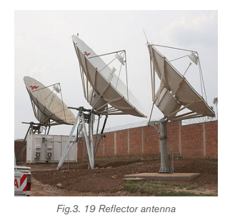
These are also called Yagi-Uda antennas or micro-strip patch arrays or aperture
arrays, slotted waveguide arrays. They are suitable for very high gain applicationswith added advantage, such as, controllable radiation pattern.
3.4.5 Advantages and disadvantages of optical fiber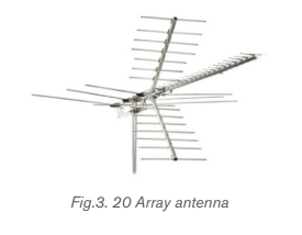
• Advantages of optical fibers are:
- The power loss is very low and hence helpful in long-distance transmissions.
- Fiber optic cables are immune to electromagnetic interference.
- These are not affected by electrical noise.
- The capacity of these cables is much higher than copper wire cables.
- Since these cables are di-electric, no spark hazards are present.
- These cables are more corrosion resistant than copper cables, as they are
bent easily and are flexible.
- The raw material for the manufacture of fiber optic cables is glass, which is
cheaper than copper.
- Fiber optic cables last longer than copper cables.
- Capacity: Optical fibers carry signals with much less energy loss than copper
cable and with a much higher bandwidth. This means that fibers can carry
more channels of information over longer distances and with fewer repeaters
required.
- Size and weight: Optical fiber cables are much lighter and thinner than
copper cables with the same bandwidth. This means that much less space
is required in underground cabling ducts. Also they are easier for installation
engineers to handle.
- Security: Optical fibers are much more difficult to tap information from
undetected; a great advantage for banks and security installations. They
are immune to electromagnetic interference from radio signals, car ignition
systems, lightning etc. They can be routed safely through explosive or
flammable atmospheres, for example, in the petrochemical industries or
munitions sites, without any risk of ignition.
- Running costs: The main consideration in choosing fiber when installing
domestic cable TV networks is the electric bill. Although copper coaxial cable
can handle the bandwidth requirement over the short distances of a housing
scheme, a copper system consumes far more electrical power than fiber,
simply to carry the signals.
• Disadvantages
Although there are many benefits to using optical fibers, there are also some
disadvantages as discussed below:
- Though fiber optic cables last longer, the installation cost is high.
- The number of repeaters is to be increased with distance.
- They are fragile if not enclosed in a plastic sheath. Hence, more protection is
needed than copper ones.
- Price: In spite of the fact that the raw material for making optical fibers,
sand, is abundant and cheap, optical fibers are still more expensive per meter
than copper. Having said this, one fiber can carry many more signals than a
single copper cable and the large transmission distances mean that fewer
expensive repeaters are required.
- Special skills: Optical fibers cannot be joined together (spliced) as an easily
as copper cable and requires additional training of personnel and expensiveprecision splicing and measurement equipment.
Application activity 3.4
1. Circle the three basic components in a fiber optic communications
system.
A. Telescope E. Maser fiber
B. Transmitter F. Optical fiber
C. Receiver G. Alternator
D. Surveillance satellites
2. Information (data) is transmitted over optical fiber by means of:
A. Light C. Acoustic waves
B. Radio waves D. None of the above
C. Cosmic rays
3. The basic unit of digital modulation is:
A. Zero D. A and B
B. One E. None of the above
C. Two
4. For each of the statements below, indicate true if it is correct and false
if it is wrong
A. Connectors and splices add light loss to a system or link.
B. The replacement of copper wiring harnesses with fiber optic cabling
will increase the weight of an aircraft.
5. 5. List two advantages and disadvantages of using optical fiber.
6. (a) Explain the optical transmitter and receiver in optical fiber
transmission system.
(b) Explain attenuation and state the measures to avoid it in optical fibertransmission system.
Skills Lab 3
In this activity you will demonstrate on how a signal can be transmitted
using water.It’s best to do it in a darkenedbathroom or kitchen at the sink or
washbasin.
You’ll need an old clear, plastic drinks bottle, the brightest flashlight (torch)
you can find, some aluminium foil, and some sticky tape.
a. Take the plastic bottle and wrap aluminium foil tightly around the sides,
leaving the top and bottom of the bottle uncovered. If you need to, hold
the foil in place with sticky tape.
b. Fill the bottle with water.
c. Switch on the flashlight and press it against the base of the bottle so the
light shines up inside the water. It works best if you press the flashlight
tightly against the bottle. You need as much light to enter the bottle as
possible, so use the brightest flashlight you can find.
d. Standing by the sink, tilt the bottle so the water starts to pour out. Keep
the flashlight pressed tight against the bottle. If the room is darkened,
you should see the spout of water lighting up ever so slightly. Notice
how the water carries the light, with the light beam bending as it goes!If you can’t see much light in the water spout, try a brighter flashlight.
End of unit 3 assessment
1. Which of the following is the most effective carrier of information?
A. Cables C . Microwaves
B. Radio waves D. Optical fibers
2. (a) An endoscope uses coherent and non-coherent fiber bundle
i) State the use of the coherent bundle and describe its
arrangement of fibers.
ii) State the use of the non-coherent bundle and describe its
arrangement of fibers.
(b) Each fiber has a core surrounded by cladding. Calculate the critical
angle at the core-cladding interface. Refractive index of core is1.52 and Refractive index of cladding is 1.
3. (a) Fig.3.21 shows a ray of light travelling through an individual fiber
consisting of cladding and a core. One part has a refractive index of1.485 and the other has a refractive index of 1.511.
i) State which part of the fiber has the higher refractive index and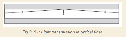
explain why.
ii) Calculate the critical angle for this fiber.
(b) The figure below shows the cross-section through a clad optical fiberwhich has a core of refractive index 1.50.
Complete the graph below to show how the refractive index changes with the
radial distance along the line ABCD in the figure above.
4. State and explain the measures to avoid the attenuation in optical fiber
transmission system
5. Estimate the length of time it would take a fiber optic systemto carry a signal from the UK to the USA under the Atlantic. (Take
a. Estimate the length of time it would take a microwave signal to travel
from the UK to the USA a satellite Enk. (Geosynchronous satellites orbit
at a height of about 86 000 km above the Earth’s surface.
b. Which would give less delay in a telephone conversation?
6. Write in your own words the description of step index fiber and graded
index fiber
7. One kind of optical fiber consists of two very thin rods one inside theother.
i) Explain why only a small amount of light is piped trough the fiber
in X.
ii) Why does the light travel along the fiber in Y without losing its
intensity.
iii) State how the inner and outer surfaces differ in their refractive
indices.
iv) Why is a fiber coated with a layer of plastic?
v) State two applications of optical fibers.8. Do fiber optics transmit radiations?