General
- Y1: Integrated Science SME File Uploaded 17/08/22, 09:33
- Y1: Integrated Science SME TG File Uploaded 17/08/22, 09:35
UNIT 20:MOMENTS AND EQUILIBRIUM OF BODIES
Key Unit Competence: Explain the principle of moments and
apply it to the equilibrium of a body.Introductory Activity 20
Study the diagrams (a), ( b) and (c) below: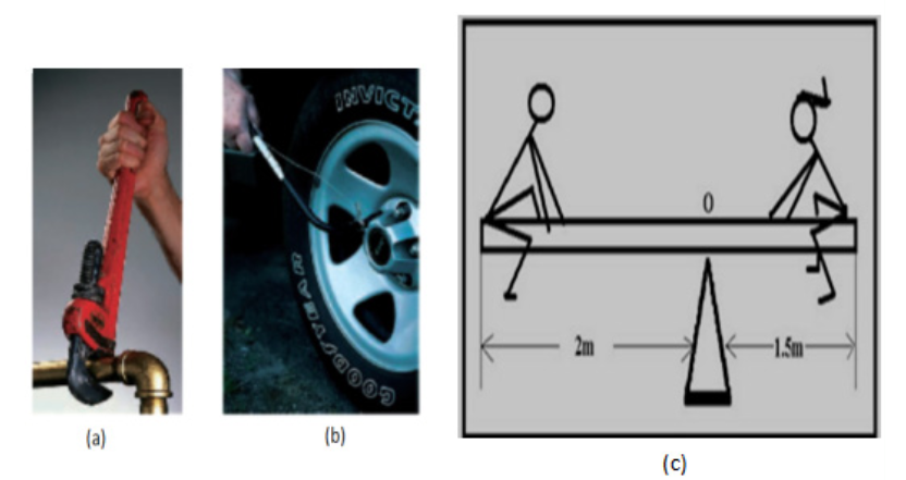
1. Referring to pictures (a) and (b), name the tools used.
2. What happens when force is applied:
i. At the end of the tool used?
ii. In the middle of the tool used?
3. Referring to (c) that shows two children balancing on a seesaw.
i. If they have different weights can they balance? Explain
ii. If they have the same weight do they balance? Explain20.1. Vector and scalar quantities
Activity 20.1
Task 1
Try to stand in a line behind one another. Push your friend.
i. What happens to your friend?
ii. How do you feel?
iii. What if in the process one stops pushing, what would happen?Task 2

Most quantities measured in science (Physics) are classified as either Scalar
or vector.A scalar quantity is a physical quantity that is defined by only magnitude
(size).Examples of scalar quantities are volume, mass, speed, and time intervals.
The rules of ordinary arithmetic are used to manipulate scalar quantities.A vector quantity is a quantity with both magnitude and direction.
Example of vector quantity: velocity, acceleration, force, weight, electric
field, displacement and pressure.20.1.1. Force as vector and moment of a force about a point
Force as vector
The force is vector quantity. We can think of force as that which causes an
object to accelerate. What happens when several forces act simultaneously
on an object? In this case, the object accelerates only if the net force acting
on it is not equal to zero.The net force acting on an object is defined as the vector sum of all forces
acting on the object. (We sometimes refer to the net force as the total force,
the resultant force, or the unbalanced force.)Moment of a force or torque
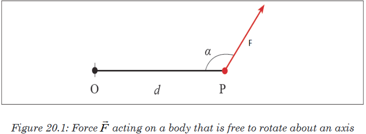
This figure shows a force
 acting on a body that is free to rotate about an
axis. The force is applied at the point P whose position is defined by the
vectorThe direction of
 and make an angle α with each other.
We define the torque acting on the body from:τ=F×d sinα
The perpendicular distance of the line of action of the force from the axis of
rotation is called the moment arm of the force.The S.I unit of torque is Newton-metre [N m] or metre-newton [m N]
20.1.2. Principles of moment
The principle of moments states that” when in equilibrium the total sum of
the anticlockwise moment is equal to the total sum of the clockwise moment.”
When a system is stable or balance it is said to be in equilibrium as all the
forces acting on the system cancel each other out. In equilibrium:
Total anticlockwise moment = Total clockwise moment
The principle can be explained by considering two people on a seesaw.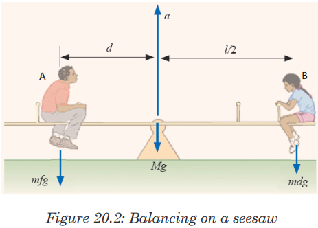
Moments acting on a seesaw
Both people exert a downward force on the seesaw due to their weights.
Person A’s weight is trying to turn the seesaw anticlockwise with person B’s
weight is trying to turn the seesaw clockwise.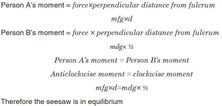
Application activity 20.1
1. Complete the following paragraph using the following words: forces,
unbalanced , accelerating, slower, balanced, resultant, faster, stay
still, and decelerating.
A ball will stay still if the forces on it are __________. If the forces
on it are unbalanced, the ball will get ______ or ______. The overall
force is called the __________ force. If something gets faster, we say
it is __________.2. A beam of negligible weight is horizontal in equilibrium, with forces
acting upon it, as shown in the diagram.
Calculate the value of the weights R and W.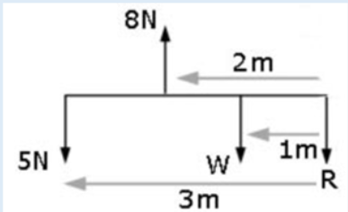
20.2. Types of equilibrium: stable, unstable and neutral
Activity 20.2
i. Displace the desk. What happens when you withdraw the force you
applied?ii. Place a bottle on a table so that it rests on its horizontal surface.
Displace or roll it. What happens?iii. Place a knife edge on a table resting on its tip. Give it a small
displacement. What happens to it?iv. From the observations made, how do you conclude?
Equilibrium has many different meanings, depending on what subject
(chemistry or physics) or what topic (energy or forces). Dealing with energy,
there are three types of equilibrium.A body is in either Stable, Unstable or in neutral equilibrium depending how
it behaves when subjected to a small displacement.Stable is when any sort of movement will raise the object’s centre of gravity.
When objects in stable equilibrium are moved, they have a tendency to fall
back to their original position. For instance, a skateboarder at the bottom, in
the middle, of a ramp. Either way the skateboarder moves, his/her potential
energy will increase because he/she will be rising in height. The boarder will
also roll back to the bottom of the ramp if he/she doesn’t exert any sort of
energy to maintain the new position.When a body returns to its original position on being slightly disturbed,
it is said to be in stable equilibrium.
Unstableis when any sort of movement will lower the object’s centre of gravity.
When such objects are moved, they cannot return to their original position
without some exertion of energy. For instance, when a coin is placed on its
side, it exhibits unstable equilibrium. Any sort of push will cause the coin to
fall flat, lowering its centre of mass. The coin will not return to its side unless
someone picks it up and resets it.If the position of a body is disturbed and the body does not return to its
original position, it is in unstable equilibrium.Neutral is when any sort of movement does not affect the object’s centre of
gravity. For instance, a ball on a table exhibits neutral equilibrium. If the ball
rolls, the centre of mass stays at the same height and thus it maintains the
same equilibrium.A body is said to be in neutral equilibrium if it moves to a new position
when it is disturbed.Let us consider a cone to understand these states.
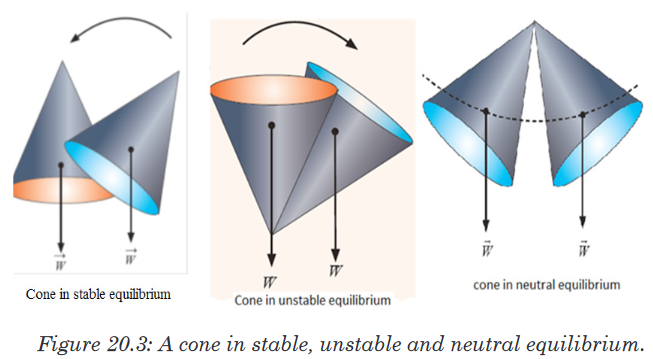
From whatever we have done, we can conclude and say that a body is
stable when:1. The object’s base is broad.
2. The centre of gravity is as low as possible.
3. The vertical line drawn from the centre of gravity should fall within
the base. Lowering the centre of gravity of an object is important for
stability.Application activity 20.2
Figure below shows a cone. Explain how to lay it on a flat table so that it is
in (a) stable equilibrium, (b) unstable equilibrium, (c) neutral equilibrium.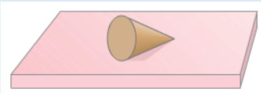
20.3. Condition for equilibrium of a body about an axis and
Stevinus proofActivity 20.3
As a class, let us move outside. With the help of a teacher outside the
class:
a). Are you seeing any object outside?
b). Are they stationary or in motion?
c). If at rest, what causes them to be at rest?20.3.1. Condition for equilibrium of a body about an axis
Objects in daily life have at least one force acting on them (gravity). If they
are at rest, then there must be other forces acting on them as well so that
the net force is zero. A book at rest on a table, for example, has two forces
acting on it, the downward force of gravity and the normal force the table
exerts upward on it.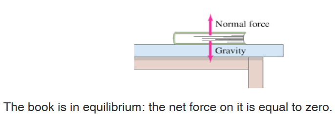
Since the net force on the book is zero, the upward force exerted by the
table on the book must be equal in magnitude to the force of gravity acting
downward on the book. Such an object is said to be in equilibrium (Latin
for “equal forces” or “balance”) under the action of these two forces. The two
conditions for equilibrium of a rigid object under the action of coplanar forces
are:1. The first or force condition: the vector sum of all forces acting on
the body must be zero: Where the plane of the coplanar forces is
taken to be the xy-plane. We must remember that if a particular
force component points along the negative x or y axis, it must have
a negative sign.
2. The second or torque condition: take an axis perpendicular to the
plane of the coplanar forces. Call the torques that tend to cause
clockwise rotation about the axis negative, and counterclockwise
torques positive; then the sum of all the torques acting on the object
must be zero:
20.3.2. Stevinus proof
Stevinus (sometimes called Stevin) proof of the law of equilibrium on an
inclined plane known as the “Epitaph of Stevinus”.He derived the condition for the balance of forces on inclined planes using
a diagram with a “wreath” containing evenly spaced round masses resting
on the planes of a triangular prism (see the illustration on the figure). He
concluded that the weights required were proportional to the lengths of the
sides on which they rested assuming the third side was horizontal and that
the effect of a weight was reduced in a similar manner.It’s implicit that the reduction factor is the height of the triangle divided by
the side (the sine of the angle of the side with respect to the horizontal). The
proof diagram of this concept is known as the “Epitaph of Stevinus”.
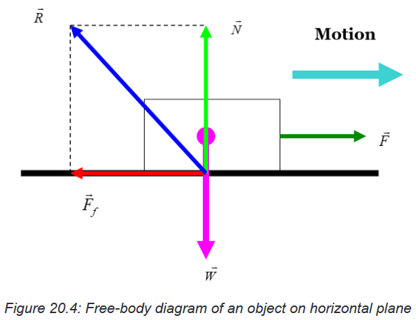
20.3.3. Free –Body Diagrams (FBD)
In physics and engineering, a free body diagram (force diagram, or FBD)
is a graphical illustration used to visualize the applied forces, movements,
and resulting reactions on a body in a given condition. They depict a body
or connected bodies with all the applied forces and moments, and reactions,
which act on the body (ies).In educational environment, learning to draw a free body diagram is an
important step in understanding certain topics in physics, such as statics,
dynamics and other forms of classical mechanics.Free body diagrams consist of:
• A simplified version of body (often a dot or a box)
• Forces shown as a straight arrows pointing in the direction they act on
the body• Moments shown as curved arrows pointing in the direction they act on
the body• Coordinate system
• Frequently reaction to applied forces are shown with hash marks
through the stem of the arrow.A number of forces and moments shown in a free body diagram depends on
the specific problem and the assumptions made; common assumptions are
neglecting air resistance, friction and assuming rigid bodies.In statics all forces and moments must balance to zero; the physical
interpretation of this is that if the forces and moments do not sum to zero the
body is accelerating and the principle of statics do not apply. In dynamics the
resultant forces and moments can be non-zero.Example: Motion on a horizontal plane with frictional force
FBD
Example 20.1: Forces on a beam and supports.
A uniform 1500-kg beam, 20.0 m long, supports a 15,000-kg printing press
5.0 m from the right support column (Figure below). Calculate the force on
each of the vertical support columns.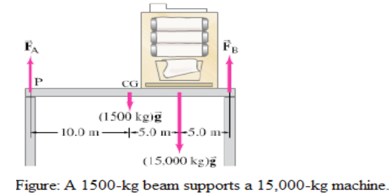
APPROACH
We analyze the forces on a beam (the force the beam exerts on each column
is equal and opposite to the force exerted by the column on the beam). We
label these forces and in the figure. The weight of the beam itself acts at its
center of gravity, 10.0 m from either end. We choose a convenient axis for
writing the torque equation: the point of application of (labeled P), so will no
enter the equation (its lever arm will be zero) and we will have an equation
in only one unknown, .
Our next example involves a beam that is attached to a wall by a hinge and
is supported by a cable or cord. It is important to remember that flexible
cable can support a force only along its length. (if there were a component
of force perpendicular to the cable, it would bend because it is flexible.) But
for a rigid device, such as the hinge in figure below, the force can be in any
direction and we can know the direction only after solving the problem. The
hinge is assumed small and smooth, so it can exert no internal torque (about
its center) on the beam.Application activity 20.3
1. A uniform beam, 2.20 m long with mass m=25.0 kg, is mounted by
a hinge on a wall as shown in figure below. The beam is held in
horizontal position by a cable that makes an angle ?=30.00as shown.
The beam supports a sign of mass M=28.0 kg suspended from its
end.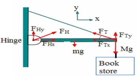
Determine the components of the force (→ F H ) that the hinge exerts on
the beam, and the tension FT in supporting cable.
2. A 5.0-m-long ladder leans against a wall at a point 4.0 m above a
cement floor as shown in figure below. The ladder is uniform and has
mass m=12.0 kg. Assuming the wall is frictionless (but the floor is not),
determine the forces exerted on the ladder by the floor and by the wall.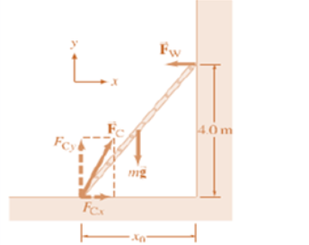
20.4. Forces and moments in equilibrium
Activity 20.4
• Try to lift your seat alone.
• How do you feel?
• Tell your friend to help you and you lift it together
• Are you feeling the same way as before when you were alone?
• What if your friend pulls in opposite direction to that of your force?
What would happen?20.4.1. Forces in equilibrium
When all the forces that act upon an object are balanced, then the object is
said to be in a state of equilibrium. The forces are considered to be balanced
if the rightward forces are balanced by leftward forces and the upward forces
are balanced by the downward forces. This however does not necessarily
mean that all the forces are equal to each other.There are two cases of equilibrium that are often encountered; the first case
deals with an object subjected to only two forces, and the second case is
concerned with an object subjected to three force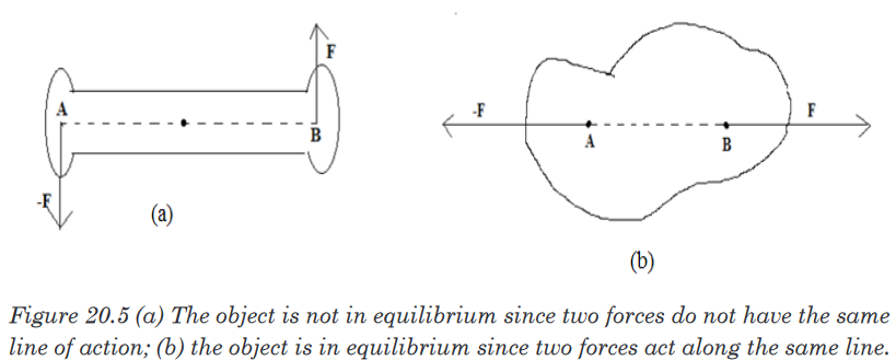
Case I: if an object is subjected to two forces, the object is in equilibrium if
and only if the two forces are equal in magnitude, opposite in direction and
have the same line of action.Figure (a) shows a situation in which the object is not in equilibrium because
the two forces are not along the same line. Note that the torque about any
axis such as one through A is not zero. Which violet the second condition of
equilibrium.Figure (b), the object is in equilibrium because the forces have the same line
of action. In this situation, it is easy to see that the net torque about any axis
is zero.Case II: If an object subjected to three forces is in equilibrium, the line of
action of the three forces must intersect at a common point; that is the force
must be concurrent. One exception to this rule is the situation in which none
of the lines of action intersect. In this situation, the forces must be parallel.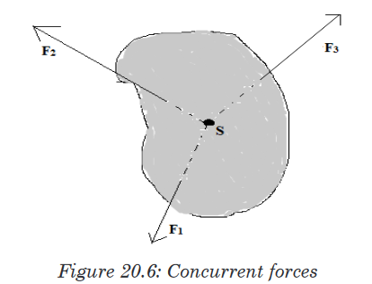
If three forces act on an object that is in equilibrium, their lines of action must
intersect at a point S (or they must be parallel).20.4.2. Couples and Torques
There are many examples in practice where two forces, acting together,
exert a moment or turning effect on some object. As a very simple case,
suppose two strings are tied to a wheel at X,Y and two equal and opposite
forces, F, are exerted tangentially to the wheel, figure below. If the wheel is
pivoted at its centre, O, it begins to rotate about O in anticlockwise direction.
The total moment about O is then
Two equal and opposite forces whose lines of action do not coincide are said
to form a couple. The two forces always has a turning effect, or moment,
called a torque, which is given bysince XY is perpendicular to each of the forces F in figure below,
The moving coil or armature in electric motor is made to spin round by a
couple. When it is working, two parallel and equal forces, in opposite
directions, act on opposite sides of the coil and produce a torque on it.In figure(ii), a wheel W is rotated about its center O by a tangential force F
at A on one side. To find the whole effect of F on the wheel, we can put two
other forces F at O which are parallel to F at A but opposite in direction. This
does not disturb the mechanics because the two forces at O would cancel
and leave F at A. But the upward force F at O and the opposite parallel force
F at A form a couple of moment . This is actually the moment of F at A.In addition, however, we are left with the downward force at O. so when F is
applied to A to turn the wheel, it produces a couple plus an equal force F at
O, the centre of the wheel.
20.4.3. Equilibrium of Coplanar forces
Forces in equilibrium mean that they are balanced.Coplanar forces act in the same plane. Two balanced forces are equal in
magnitude but opposite in direction to the other.Parallelogram of forces
A force is a vector quantity. So it can be represented in size and direction by
a straight line drawn to scale. The sum or resultant of two forces and can
be added by one of two vector methods.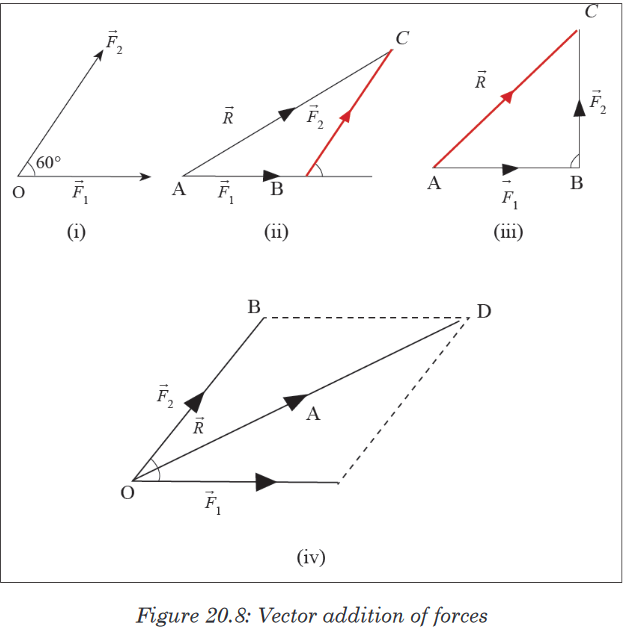
If three forces are in equilibrium, they can be represented in magnitude and
direction by the three sides of a triangle taken in order. This is called the
triangle of forces theorem. This result can be extended to many forces in
equilibrium.20.4.4. Equilibrium of moments of force
We consider the equilibrium of an object like a horizontal bar. In the lab it
will be a meter stick. Equilibrium means that it does not have translation
(motion in which all points on the body move with the same vector velocity)
or rotation.We can define the rotation by choosing any point on the body, calling that
point the “axis”, and considering rotation about that axis.There may be several forces acting on the body, and each force acts at
certain point. In the diagram, acts at point and acts at point; A is the axis.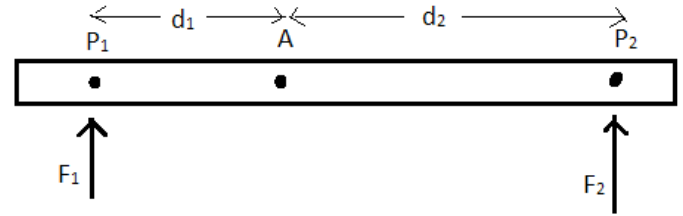
We consider only forces that act up or down. The distance from point where
the force acts to the axis is called the moment arm, and in the diagram. The
product of the force times the moment arm is called the torque (also called
the moment), and is represented by a Greek letter tauTorque also has a sign: it is positive (by convention) if it tends to rotate
the object in counterclockwise direction around the axis. It is negative if it
tends to rotate the object in a clockwise direction around the axis. In the
diagram the torque due to is positive and the torque to is negative. The
forces themselves have signs. We may take forces positive if directed up,
and negative down.The conditions for equilibrium are then stated simply: the sum of all forces
must be zero, and the sum of all torques must be zero. One particular force
requires further consideration: the weight of the bar. The weight (force of
earth’s gravity) does not act at a point, but acts at all points along the object.
However, for the purposes of determining equilibrium, the weight can be
considered to be concentrated at a single point, called the center of mass.
Thus a bar supported by two upward forces, and held in equilibrium, looks
like the figure below.
Since the axis, for problem-solving purposes, can be chosen anywhere along
the bar, it is convenient to choose it at the point where one of the forces acts.
Then the moment arm of that force will be equal to zero, and so that force
will not come into torque equation. For example, we may choose the axis to
be at the center of mass.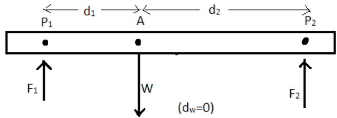

Application activity 20.4
Determine the mass of the object using the principle of moments.
Apparatus required
• 1 uniform meter rule
• A knife edge
• Unknown mass
Instructions
Follow these steps to determine the mass M of the provided body (meter
ruler).a) Weigh the meter ruler provided to obtain its mass, M. Balance the
meter ruler on a knife edge. Read Q the balance point. Find Z.b) Balance the meter ruler with its graduated face upwards on a knife
edge. With the mass M provided at P=10 cm from A as shown,c) Measure and record distance X and Y.
d) Repeat procedure (b) and (c) for values of P=15, 20, 25, 30 and
35cm.e) Tabulate your results including values of (Y-Z) and (X-P).
f) Plot a graph of (Y-Z) against (X-P).
g) Find the slope “S’’ of your graph.
20.5. Archimedes’ principle of the lever and centre of
gravity of bodiesActivity 20.5
Task 1
1. In group, discuss levers using knowledge of O’ level Machines.
2. What is your friend telling you? Is it what you knew before?
Task 2
Given a pencil, a ruler, a notebook or other regular shaped material
Tray to balance the material using your finger. Is it balanced? What
causes it to be balanced? How do you call the point of balance? How can
you locate this point?20.5.1. Archimedes and the principle of the lever
Building up from the earliest remaining writings regarding levers date from
the 3rd century BC and were provided by Archimedes. “Give me a place
tostand, and I shall move the Earth with it” is a remark of Archimedes who
formally stated the correct mathematical principle of lever.Force and levers, law of the lever
A lever is a beam connected to ground by a hinge or pivot called a fulcrum.
In other words we say that the lever is a movable bar that pivots on a fulcrum
attached to a fixed point. The lever operates by applying forces at different
distances from the fulcrum, or a pivot.The ideal lever does not dissipate or store energy, which means there is
no friction in the hinge or bending in the beam. In this case, the power into
the lever equals the power out, and the ratio of output to input force is given
by the ratio of the distances from the fulcrum to the points of application of
these forces. This is known as the law of the lever.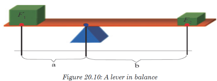
The mechanical advantage of a lever can be determined by considering the
balance of moments or torque, τ, about the fulcrum, and we write: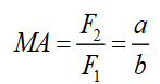
where F1 is the input force to the lever and F2 is the output force. Then
distances a and b are the perpendicular distances between the forces and
the fulcrum.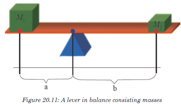
For the case of the figure 20.11, knowing that the forces considered are
weights of objects and W = Mg, we can write the mechanical advantage of
the lever as a ratio,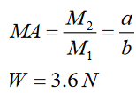
20.5.2. Centre of gravity and the total weight centre of gravity of
a flat objectIn most equilibrium problems, one of the forces acting on the body is the
weight. We need to be able to calculate the torque of this force. The weight
doesn’t act at a single point; it is distributed over the entire body. But we can
always calculate the torque due to the body’s weight by assuming that the
entire force of gravity (weight) is concentrated at a point called the center
of gravity (abbreviated “ cg”). The acceleration due to gravity decreases with
altitude; but if we can ignore this variation over the vertical dimension of
the body, then the body’s center of gravity is identical to its center of mass
(abbreviated “cm”), let us prove it.First let’s review the definition of the center of mass. For a collection of
particles with masses m1, m2,and coordinates (x1,y1,z1 )(x2,y2,z2 ) the
coordinates and of the center of mass are given by
Also, xcm,ycm and zcm are components of the position vector of center of mass,
so this is equivalent to the vector equation
Now let’s consider gravitational torque on a body of arbitrary shape
We assume that the acceleration due to gravity has the same magnitude and
direction at every point in the body. Every particle in the body experiences a
gravitational force, and the total weight of the body is a vector sum of a large
number of parallel forces. A typical particle has mass and weight . If is the
position vector of this particle with respect to an arbitrary origin O, then the
torque vector of the weight with respect to O is,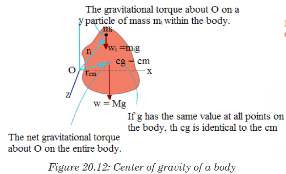
The total gravitational torque is the same as though the total weight
 were
were
acting on the position of the center of mass, which we also call the center
of gravity. If has the same value at all points on a body, its center of gravity
is identical to its center of mass. Note, however, that the center of mass is
defined independently of any gravitational effect. While the value of does
does
vary somewhat with elevation, the variation is extremely slight. Hence we
will assume that the center of gravity and the center of mass are identical
unless explicitly stated otherwise.20.5.3. Equilibrium of a system of objects
Balancing turning forces
An object in static equilibrium is one that has no acceleration in any direction.
While there might be motion, such motion is constant.Two children on a seesaw: the system is in static equilibrium, showing no
acceleration in any direction.When an object is balanced on a pivot the turning effect of the forces
on one side of the pivot must balance the turning effect of the forces
on the other side of the pivot - if they didn’t it would not balance.
In the picture (Figure 20.13(a)) two girls are sitting on a see saw. They have
moved until it is balanced. They are the same weight and so to balance the
see saw they must sit the same distance from the pivot.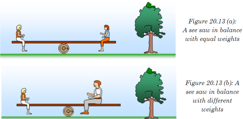
In the picture (Figure 20.13(b)) one of the girls gets off and a man sits on
instead. They move until the see saw is balanced. The girl is much lighter
than the man and so she has to sit further away from the pivot then he does
so that she can balance his extra weight.You should remember that the turning effect of a force is called the moment
of the force and is found by multiplying the force by its distance from the pivot.
When the see saw is balanced we say that the anticlockwise moments (those
trying to turn the object anticlockwise) equal the clockwise moments (those
trying to turn the object clockwise). In our example the man’s weight tries to
turn the see saw clockwise and the girl’s weight tries to turn it anticlockwise.
You can investigate this in the lab by using sets of weights hanging on a
wooden ruler (Figure 20.14)
The rule for something to be balanced is called the principle of moments and
is written as follows: when an object is balanced (in equilibrium) the sum of
the clockwise moments is equal to the sum of the anticlockwise moments.Force 1 x perpendicular distance 1 = Force 2 x perpendicular distance 2
from pivot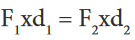
Example 20.2: Balancing a seesaw.
A board of mass M = 2.0 kg serves as a seesaw for two children, as shown in
figure below. Child A has a mass of 30 kg and sits 2.5m from the pivot point,
P (his center of gravity is 2.5m from the pivot).At what distance x from the pivot must child B, of mass 25 kg, place herself
to balance the seesaw? Assume the board is uniform and centered over the
pivot.
Approach
We follow the steps of the problem solving box explicitly.
Solution
1. Free-body diagram. We choose the board as our object, and assume it
is horizontal. Its free-body diagram is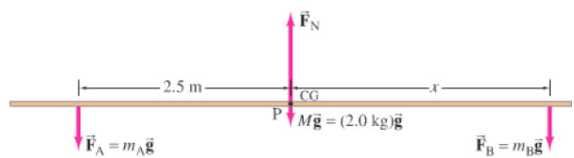
The forces acting on the board are the forces exerted downward on it
by each child,
 and
and  , the upward force exerted by the pivot
  and
and
the force of gravity on the board (= Mg) which acts at the center of the
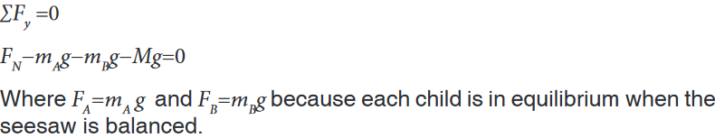
uniform board.2. Coordinate system. We choose y to be vertical, with positive upward,
and x horizontal to the right, with origin at the pivot.3. Force equation. All the forces are in the y (vertical) direction, so
4. Torque equation. Let us calculate the torque about an axis through the
board at the pivot point, P. then the lever arm for FN and for weight of
the board are zero , and they will contribute zero torque (about point P)in our torque equation. Thus the torque equation will involve only the
forces
 and
and  , which are equal to the weights of children. The torque
exerted by each child will be mg times the appropriate lever arm, which
here is the distance of each child from the pivot point. Hence the torque
equation is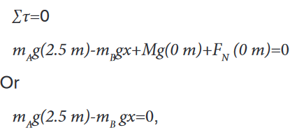
where two terms were dropped because their lever arms were zero.
5. Solve. We solve the torque equation for x and find
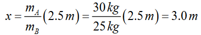
To balance the seesaw, child B must sit so that her CM is 3.0 m from the
pivot point. This makes sense: since she is lighter, she must sit farther from
the pivot than the heavier child.Application activity 20.5
A seesaw consisting of a uniform board of mass M = 10 kg and length l =
2 m supports a father and a daughter with mass mf and md, 50 kg and 20
kg respectively as shown in the figure. The support (called the fulcrum) is
under the centre of gravity of the board. The father is a distance d from
the center, and the daughter is at distance l/2 from the center.a) Determine the magnitude of the upward force (reaction) n exerted
by the support on the board.b) Determine where the father should sit to balance the system.

Skills lab 20
Title: determination of the mass of the meter rule
Apparatus: 2 meter rules, knife edge, 6 masses of 10 g,Procedure
1. Balance the meter rule provided on a knife edge with the graduated
side facing upwards.2. Note the balance point P and record its distance from B.
3. Place a mass M of 10 g on the top of mater rule at the 10 cm mark and
balance the arrangement as shown in figure below.4. Read and record distance l1 and l2
5. Repeat the procedures (3) and (4) from the values of M = 20,30,40,50,
and 60g.6. Record your results in a suitable table including the values of l2−l0 and

7. Plot a graph of M against

8. Find the slope of your graph.
End unit assessment 20
1. ............................ is an example of a scalar quantity
a) Velocity. b) Force. c) Volume. d) Acceleration.2. ............................ is an example of a vector quantity
a) Mass. b) Force. c) Volume. d) Density.3. A scalar quantity:
a) Always has mass.
b) Is a quantity that is completely specified by its magnitude.
c) Shows direction.
d) Does not have units.4. A vector quantity
a) Can be a dimensionless quantity.
b) Specifies only magnitude.
c) Specifies only direction.
d) Specifies both a magnitude and a direction.5. A boy pushes against the wall with 50 kilograms of force. The wall
does not move. The resultant force is:
a) -50 kilograms.
b) 100 kilograms.
c) 0 kilograms.
d) -75 kilograms.6. a) State the principle of moment
b) What are the conditions for equilibrium?7. Calculate the magnitudes FA and FB of the tensions in the two
cords that are connected to the vertical cord supporting the 200kg
chandelier in the following figure.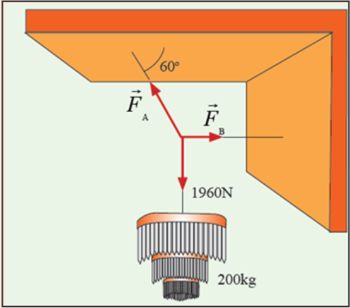
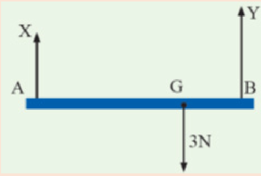
8. A horizontal rod AB is suspended at its ends by two strings. (See the
figure below). The rod is 0.6m long and its weight of 3N acts at G
where AG is 0.4m and BG is 0.2m. Find the tensions X and Y