General
- Y1: Integrated Science SME File Uploaded 17/08/22, 09:33
- Y1: Integrated Science SME TG File Uploaded 17/08/22, 09:35
UNIT 13:KIRCHHOFF’S LAWS IN ELECTRIC CIRCUITS
Key unit competence: Interpret and solve problems in electric
circuits using Kirchhoff’s lawsIntroductory Activity 13
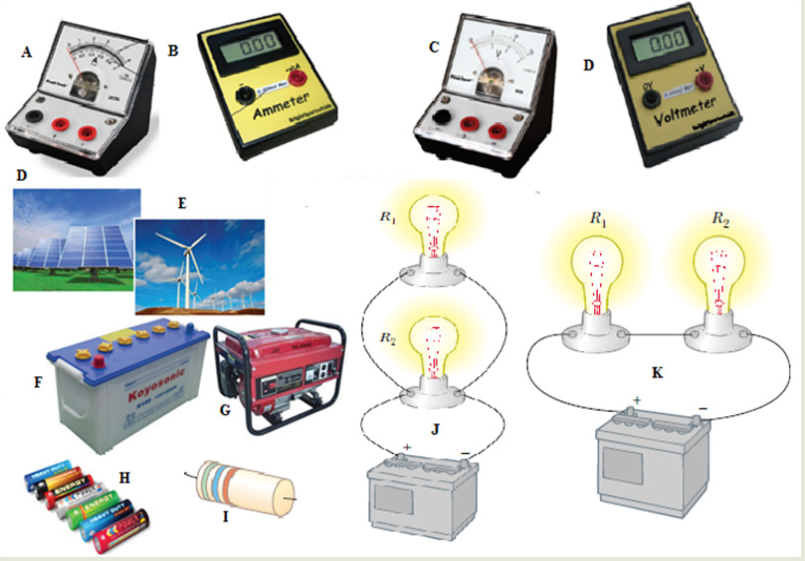
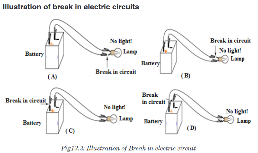
Look at the illustration given above.
a). What type of devices available in the illustration above?
b). Can you suggest the names of the available devices in the illustration
above?
c). Is there any complete circuit in the illustration above?
d). What kind of electrical circuits identified in the illustration above?e). Have you ever used or connected these electrical components
somewhere? If yes, what were the difficulties in handling these
electrical components in circuit construction?
f). What can be considered to select the best electrical device(s) to be
used in electrical circuit construction?
g). What can be put in recognition to minimize risks when connecting
these electrical components in the circuit?13.1. Simple electric circuits and its construction
Activity 13.1
Observe the following diagram and answer the next questions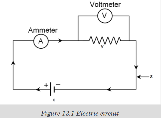
a). Explain the role of part X, Y, Z
b). Give any example of device that is represented by X and Y.
c). Are ammeters and voltmeters necessary in creation of simple electric
circuit? Explain.
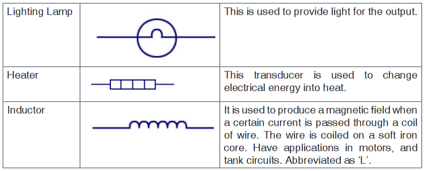
d). Give other necessary devices in simple electrical circuit.13.1.1. Electric circuit components, devices and their symbols
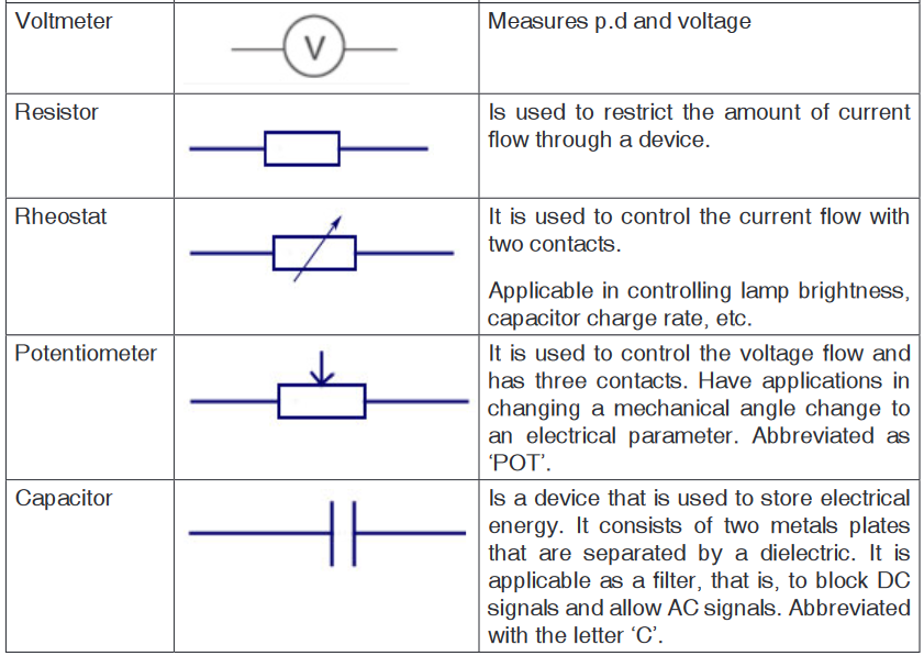
In electric circuit diagrams, we represent the actual components with
symbols. Table below shows some of the components, their symbols and
definition that are used in electric circuit diagrams.
13.1.2. Sample arrangement of electric components in a simple
electric circuit
Remember the cell provides electrical energy needed to light the bulb. The
bulb converts electrical energy into light and heat energy.A cell is a kind of a ‘pump’ which provides electrical energy needed to drive
charges along a complete path formed by the wire through the bulb switch
and back again to the cell.When the switch is open, the bulb does not light. This is called an open
circuit. When the bulb lights the circuit is called closed circuit.In a series circuit, the current is the same at all points; it is not used up. In a
parallel circuit the total current equals the sum of the currents in the separate
branches.Schematic diagram and its corresponding illustrations:

Application activity 13.1
1. Define the term electric circuit.
2. Draw a diagram for a simple circuit using preferable electric
components.
3. What is an open circuit?
4. The following are some symbols of electric components.
a). Name the electric components represented by these symbol.
b). Using these symbols, draw a simple circuit diagram.13.2. Measurement of electric current and voltage in a
simple electric circuitApplication activity 13.2
Interpret the scale on the figure below for an analogue ammeter that
measures current in the range 0 – 1 A, or 0 – 5 A. Determine the reading
of the Ammeter.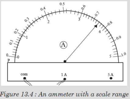
Measurement of electric current
Ammeter has two positive terminals and one negative terminal. Fig. (a)
Shows an analogue ammeter and (b) shows a digital ammeter.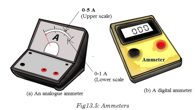
An analogue ammeter may have more than one scale (Fig.(a)). The
magnitude of the current determines the scale to be used. Smaller currents
are measured in milliamperes (mA) and microamperes ( A).
1 mA = 1/ 1 000 A = 1 x10⁻³ A, 1μ A = 1 10-6 A.How to use an ammeter to measure current in a circuit
Reading an analogue ammeter
Figure below shows the scale on an analogue ammeter that measures
current in the range 0 – 1 A, or 0 – 5 A.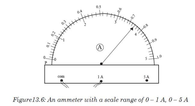
When connected to the 1 A terminal, the upper scale running from 0 - 1 A
should be used.We determine the current represented by each smallest division on the
upper scaleas follows:
5 divisions correspond to........... 0.1 A
1 division corresponds to .................................. 0.1/5A = 0.02 A
In Figure 13.6, the pointer is on the second mark after the 0.7 mark, hence
the ammeter reading is:
0.7 A + (2 divisions × 0.02 A) = 0.7A + 0.04 A = 0.74 APotential difference (p.d)
Potential difference is defined as the work done in moving one coulomb
of charge from one point to the other in an electrical circuit. The SI unit of
potential difference is the volt (V).In the electric circuit, the electrons move towards the positive terminal of the
battery. The battery lifts the electrons up through an electrical height. This
electrical height is called a potential.The positive and the negative terminals have a difference in potential. The
potential difference is also known as the voltage.
1 volt is therefore defined as the energy needed to move one coulomb of
charge from one point to another.Measurement of voltage
Figure 13.7(a) shows analog voltmeter and (b) shows digital voltmeter the
symbol for a voltmeter. A voltmeter is used to measure voltage across a
device in an electric circuit.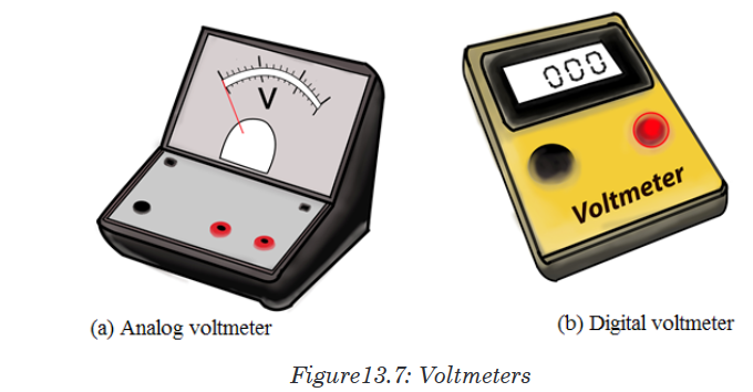
The positive terminal of voltmeter is connected to the wire from the positive
terminal of the cells and the negative terminal to the wire leading to negative
terminal. A voltmeter is always parallel to the device whose voltage is to be
measured.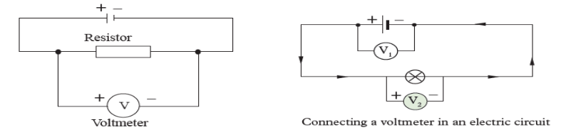
Voltmeters have uniform scales calibrated in volts or mill-volts. The most
used scales have a range of 0 – 5 V and 0 – 1.5 V. Figure below shows a
scale of a voltmeter.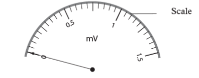
Application activity 13.2
1. Define the term potential difference and state its SI units.
2. Name the instrument used to measure voltage.
3. Define a volt.
4. In a circuit, 5 joules are used to drive 2 coulombs of charge across a
bulb in a simple circuit. Find the potential difference across the bulb?
5. Name the instrument used to measure potential difference.
6. Two cells, A and B connected in parallel are in series with a bulb as
shown in Figure below.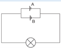
Figure13.8: Circuit with parallel cells
Copy the diagram and show where the:
a). Ammeter should be connected in order to measure the current
through cell A.
b). Voltmeter should be connected to measure the potential difference
across both the bulb and cell B.13.3. Different sources of electric current
Activity 13.3
Search on internet about different sources of electric current and answer
the following questions.a). What is a source of electric current?
b). What is another name of electric source of energy?
c). List some of electric sources you have found.
d). On the picture below are some sources of electric energy: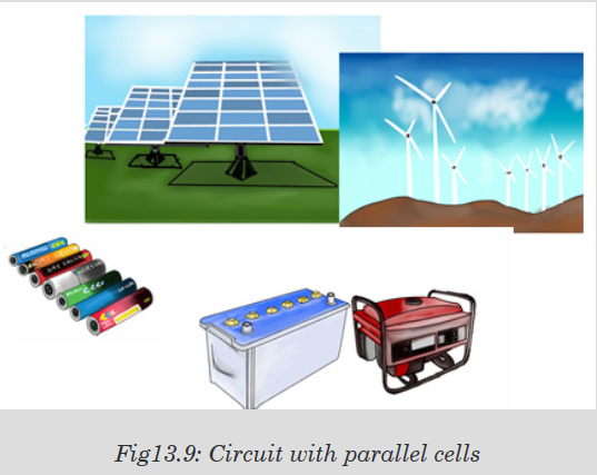
• Name them and tell what the common role they have.
• Tell what energy is changed in electric energy for each device.
There are several different devices that can supply the voltage necessary to
generate an electric current. The two most common sources are generators
and electrolytic cells.Generators use mechanical energy, such as water pouring through a dam or
the motion of a turbine driven by steam, to produce electricity. The electric
outlets on the walls of homes and other buildings, from which electricity to
operate lights and appliances is drawn, are connected to giant generators
located in electric power stations. Each outlet contains two terminals. The
voltage between the terminals drives an electric current through the appliance
that is plugged into the outlet.Generator electrolytic cells use chemical energy to produce electricity.
Chemical reactions within an electrolytic cell produce a potential difference
between the cell’s terminals. An electric battery consists of a cell or group of
cells connected together.There are many sources of electric current other than mechanical generators
and electrolytic cells. Fuel cells or engines, for example, produce electricity
through chemical reactions. Unlike electrolytic cells, however, fuel cells do
not store chemicals and therefore must be constantly refilled.Certain sources of electric current operate on the principle that some metals
hold onto their electrons more strongly than other metals do. Platinum, for
example, holds its electrons less strongly than aluminum does. If a strip ofplatinum and a strip of aluminum are pressed together under the proper
conditions, some electrons will flow from the platinum to the aluminum. As
the aluminum gains electrons and becomes negative, the platinum loses
electrons and becomes positive.The strength with which a metal holds its electrons varies with temperature.
If two strips of different metals are joined and the joint heated, electrons will
pass from one strip to the other. Electricity produced directly by heating is
called thermoelectricity.Some substances emit electrons when they are struck by light. Electricity
produced in this way is called photo-electricity. When pressure is applied
to certain crystals, a potential difference develops across them. Electricity
thus produced is called piezoelectricity. Some microphones work on this
principle.Notice: An electric generator is a device which is used to produce electric
energy, which can be stored in batteries or can be directly supplied to the
homes, shops, offices, etc. Electric generators work on the principle of
electromagnetic induction. A conductor coil (a copper coil tightly wound
onto a metal core) is rotated rapidly between the poles of a horseshoe type
magnet. A conductor coil (a copper coil tightly wound onto a metal core) is
rotated rapidly between the poles of a horseshoe type magnet. The conductor
coil along with its core is known as an armature. The armature is connected
to a shaft of a mechanical energy source such as a motor and rotated. The
mechanical energy required can be provided by engines operating on fuels
such as diesel, petrol, natural gas, etc. or via renewable energy sources
such as a wind turbine, water turbine, solar-powered turbine. When the coil
rotates, it cuts the magnetic field which lies between the two poles of the
magnet. The magnetic field will interfere with the electrons in the conductor
to induce a flow of electric current inside it.Application activity 13.3
1. Sources of electric current are also known as electric generators.
Explain electric generators.
2. What is an engine? Compare engine to batteries.
3. Compare and contrast battery from dry cells
4. Research on differences between piezoelectricity and thermoelectricity.
5. Research on differences between renewable and non- renewable
form of energy sources.13.4. Connection of electrical current source and resistors
Activity 13.4Task1: Series circuits
Provided materials: Battery cells, three torch light bulbs and conducting
wiresTechnical procedure:
• Arrange the battery cells as shown in figure below.
• Connect all the two bulbs in series and switch on.
• Remove one bulb and discuss your observations.
• Arrange the circuit to have two bulbs, and then to have one bulb
and discuss the observation.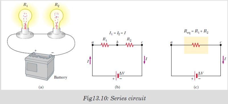
Use your observations to answer the following questions:
1. What happens in the circuit with three bulbs when one bulb is
removed?
2. What happens when the circuit has two bulbs?
3. What happens when the circuit has one bulb only?Task 2: Parallel circuits
Materials: Battery cells, two torch light bulbs and conducting wiresTechnical procedure:
• Arrange the battery cells as shown in figure 13.11.• Connect all the three bulbs in parallel and switch on.
• Remove one bulb and discuss your observations.
• Remove the second bulb and discuss your observations.
Use your observation to answer to questions below:
1. What happens in the circuit with two bulbs when one bulb is removed?
2. What happens when the circuit has two bulbs?
3. What happens when the circuit has one bulb only?Circuits consisting of just one battery and one load resistance are very
simple to analyze, but they are not often found in practical applications.
Usually, we find circuits where more than two components are connected
together. There are two basic ways in which to connect more than two circuit
components: series and parallel.13.4.1. Resistors in series
The defining characteristic of a series circuit is that there is only one path for
electrons to flow. Consider three resistors R1, R2 and R3 connected in series
across a battery of potential difference V. Across the resistors the potential
difference drops are V1, V2 and V3 but the current flow I is constant due to
the same amount of charges flowing across each resistor.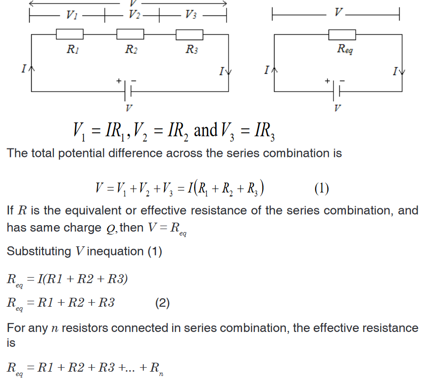
13.4.2. Resistors in parallel
The defining characteristic of a parallel circuit is that all components are
connected between the same set of electrically common points and the
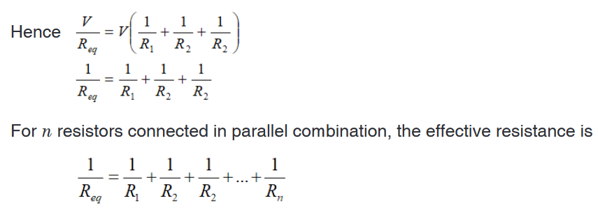
resistors form more than one continuous path for electrons to flow.Assume three resistors of resistance R1, R2 and R3 connected in parallel
across a battery of potential difference V. The potential difference across
each resistor is the same and is equal to the potential difference V across
the battery, but the current flow splits into three parts I1, I2 and I3 due to the
separation of charges.
Household circuits are always wires so that the lights and appliances are
connected in parallel. This way each device operated independently of
the others, so if one is turned off the others remain on. This also had the
advantage that the voltage supplied to each element is the same.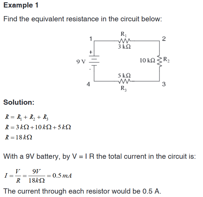
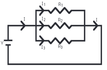
Example 2
A parallel circuit is shown in the figure below. In this case the current supplied
by the battery splits up, and the amount going through each resistor depends
on the resistance.From the figure below, if the values of the three resistors are
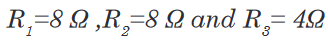
Determine the total resistance of the circuit.
Solution
The total resistance R is found by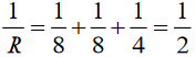
This gives that R=2Ω
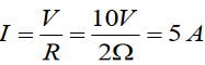
With a 10 V battery, by V = I R the total current in the circuit is:
The individual currents can also be found using
 The voltage across
each resistor is 10 V, so: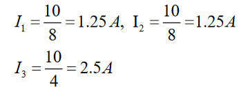
Note that the currents add together to 5A, the total current.
Example 3
Interpret the circuit below and determine the total resistance of the circuit.
Solution
Here we can use the shorter product over sum equation as we only have two
parallel resistors.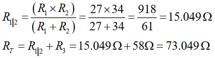
Application activity 13.4
1. Use the concept of equivalent resistance to determine the unknown
resistance of the identified resistor that would make the circuit’s
equivalent.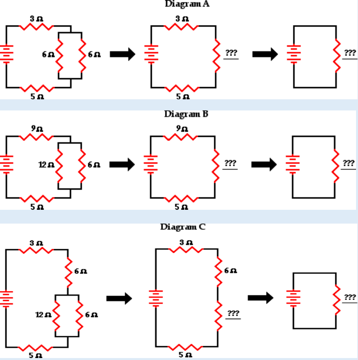
2. A parallel pair of resistance of value of Ω3 and Ω6 are together
connected in series with another resistor of value Ω4 and a battery
of e.m.f. 18 V as shown on the fig. (a) below. Calculate the current
through each resistor.
Calculate the current through each resistor.
3. (a) Find the equivalent resistance between points a and b in Figure
below. (b) A potential difference of 34.0 V is applied between points a
and b. Calculate the current in each resistor.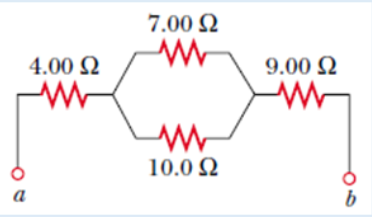
4. Use your understanding of equivalent resistance to complete the
following statements:i. Two 3Ω resistors placed in series would provide a resistance
which is equivalent to one ___ Ω resistor.ii. Three 3Ω resistors placed in series would provide a resistance
which is equivalent to one ___ Ω resistor.
iii. Three 5Ω resistors placed in series would provide a resistance
which is equivalent to one ___ Ω resistor.
iv. Three resistors with resistance values of 2Ω , 4Ω and 6Ω are
placed in series. These would provide a resistance which is
equivalent to one ___ Ω resistor.
v. Three resistors with resistance values of 5Ω , 6Ω and 7Ω are
placed in series. These would provide a resistance which is
equivalent to one _____ Ω resistor.
vi. Three resistors with resistance values of 12Ω, 3Ω and 21Ω are
placed in series. These would provide a resistance which is
equivalent to one _____ Ω resistor.5. As the number of resistors in a series circuit increases, the overall
resistance __________ (increases, decreases, remains the same)
and the current in the circuit __________ (increases, decreases,
remains the same).6. Imagine that we add a third resistor in series with the first two. Does
the current in the battery (a) increase, (b) decrease, or (c) remain
the same? Does the terminal voltage of the battery (d) increase, (e)
decrease, or (f) remain the same?7. Imagine that we add a third resistor in parallel with the first two. Does
the current in the battery (a) increase, (b) decrease, or (c) remain
the same? Does the terminal voltage of the battery (d) increase, (e)
decrease, or (f) remain the same?13.5. Kirchhoff’s laws and its applications in solving
problems in electric circuitsActivity 13.5
A single-loop circuit contains two resistors and two batteries, as shown
in the following figure (neglect the internal resistances of the batteries).
a). Find the current in the circuit.
b). What power is delivered to each resistor? What power is delivered
by the 12V battery?
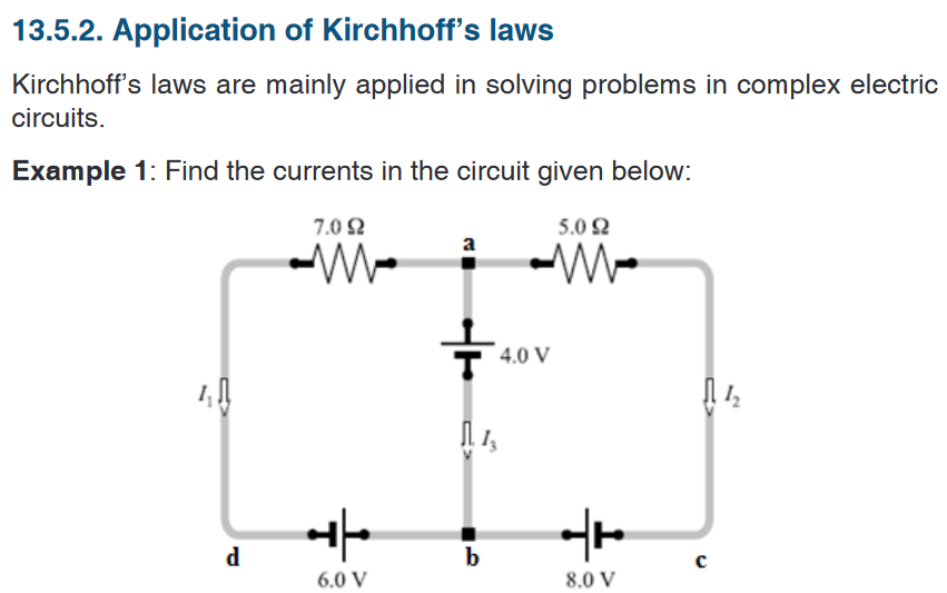
13.5.1. Kirchhoff’s laws
Simple circuits can be analyzed using the expression V = IR and the rules for
series and parallel combinations of resistors. Very often, however, it is not
possible to reduce a circuit to a single loop.The procedure for analyzing more complex circuits is greatly simplified if
we use two principles called Kirchhoff’s rules developed by the German
Physicist Gustav Robert Kirchhoff (1824-1887).First, here are two terms that we will use often. A junction in a circuit is a
point where three or more conductors meet. Junctions are also called nodes
of branch points. A loop is any closed conducting path.In figure 13.13 below, the points a and b are junctions, but points c and d are
not. The curved lines show some possible loops in this circuits.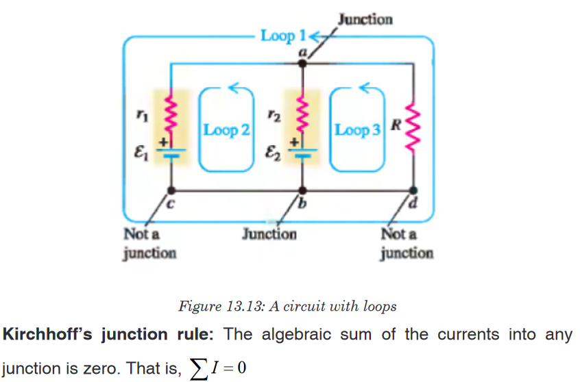
i.e The sum of the currents entering the junction must equal the sum of the
currents leaving the junction.Kirchhoff’s loop rule: The algebraic sum of the potential differences in any
loop, including those associated with emfs and those of resistive elements,
must equal zero. That is,
Kirchhoff’s first rule is a statement of conservation of electric charge. All
charges that enter a given point in a circuit must leave that point because
charge cannot build up at a point.Kirchhoff’s second rule follows from the law of conservation of energy.
The sum of the increases in energy as the charge passes through some
circuit elements must equal the sum of the decreases in energy as it passes
through other elements. The potential energy decreases whenever the
charge moves through a potential drop –IR across a resistor or whenever it
moves in the reverse direction through a sourceof emf. The potential energy
increases whenever the charge passes through abattery from the negative
terminal to the positive terminal.When applying Kirchhoff’s second rule in practice, we imagine traveling
around the loop and consider changes in electric potential, rather than the
changes in potential energy.Problem solving strategy
Junction rule: Assign symbols and directions to the currents in the various
junctions. If you guess the wrong direction for a current it does not matter.
The end result will be a negative answer for that current and the magnitude
will be correct.Loop rule: You must choose a direction for moving around the loop. As you
move around the loop the voltage drops and increases should be recorded
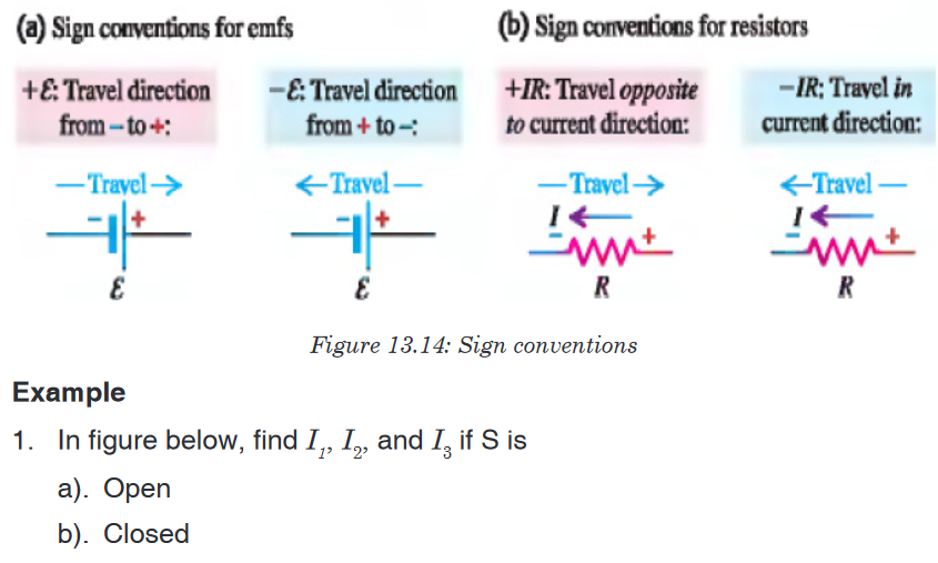
according to the rules (a-d) below.a). If a resistor is traversed in the direction of the current, the change in
potential across the resistor is –IR.
b). If a resistor is traversed in the direction opposite the current, the
change in potential across the resistor is +IR.
c). If a source of emf is traversed in the direction of the emf (from – to +)
the change in potential is .
d). If a source of emf is traversed opposite the direction of the emf (from
+ to –) the change in potential is .
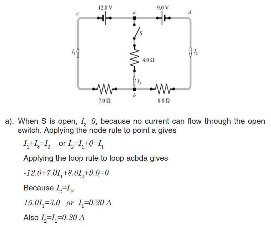

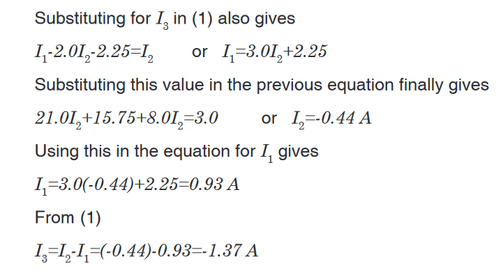
Solution
This circuit cannot be reduced further because it contains no resistors in
simple series or parallel combinations. We therefore revert to Kirchhoff’s
rules. If the currents had not been labeled and shown by arrows, we would
do that first. No special care needed to be taken in assigning the current
directions, since those chosen incorrectly will simply give negative numerical
values.We apply the node rule to node b in the figure above.
Current into b = Current out of b.

The minus sign tells us that I3 is opposite in direction to that shown in the
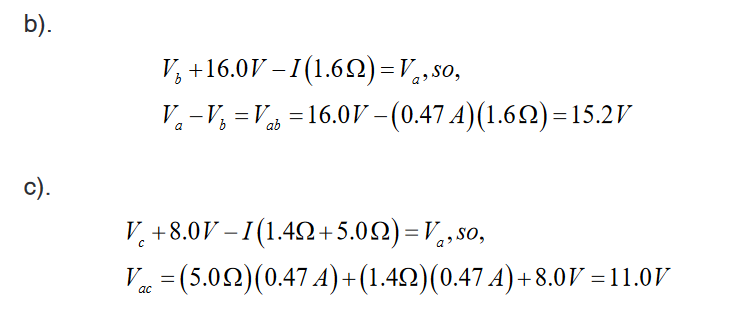
figure.Example 2: The circuit shown in figure below contains two batteries, each
with an emf and an internal resistance, and two resistors. Find (a) the current
in the circuit (magnitude and direction); (b) the terminal voltage Vab of the
16.0 V battery; (c) the potential difference Vac of a with respect to point c.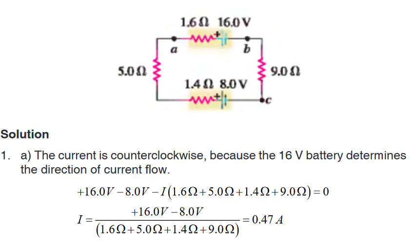
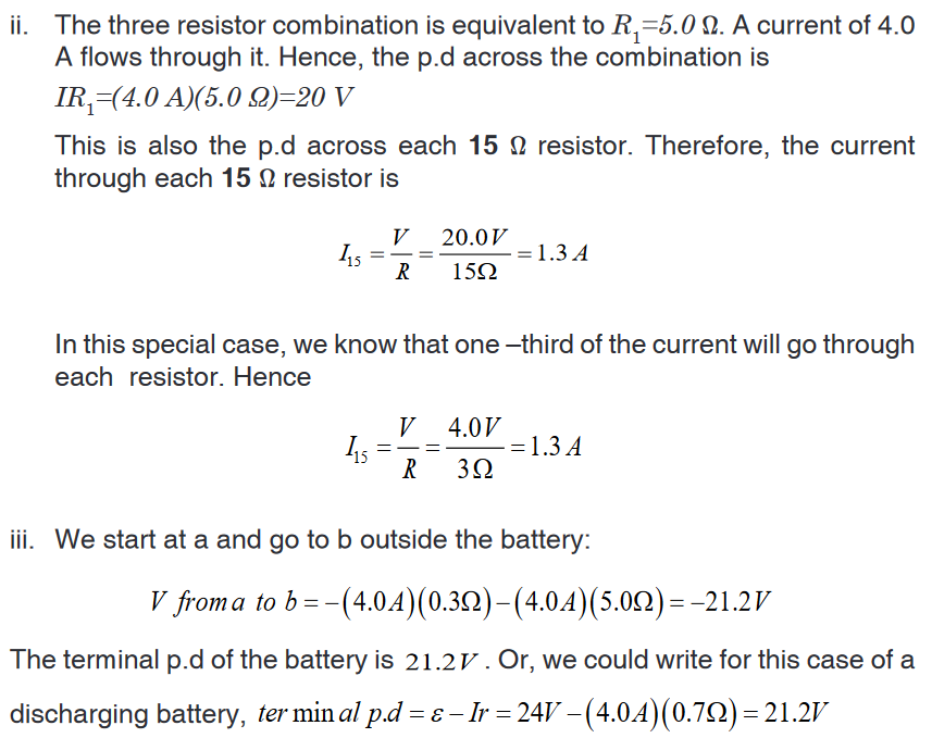
Example 3: In figure below, the battery has an internal resistance of 0.7Ω.
Find:
i. The current drawn from battery,
ii. The current in each 15 Ω resistor,
iii. The terminal voltage of the battery.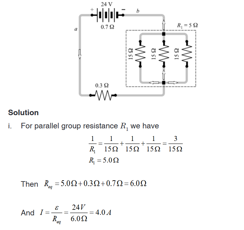
Application activity 13.5
In the circuit below, each cell has e.m.f of 1.5 V and zero internal
resistance. Each resistor has a resistance of 10 Ω. There are currents I1
and I2 in the branches as shown.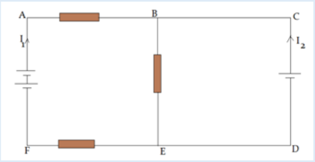
a). Use Kirchhoff’s first law to write down an expression for the current in
BE, in terms of I1 and I2
b). Use Kirchhoff’s first law to write down equations for the circuit loops
i) ABEFA ; ii) CBEDCSkills lab 13
Conduct a survey to find out how people construct electric circuits and apply
Kirchhoff’s laws in analysis of complex electric circuits before installation
process.Collect and analyze data about when, where, and why people use Kirchhoff’s
laws in dealing with complex electric circuits.To complete this project you must
• Develop a survey sheet about electric components, demonstration of
Kirchhoff’s laws and complex electric circuit.
• Distribute your survey sheet to other student-teachers, family members
and neighbors.
• Compile and analyze your data.
• Create a report to display your findings in your sheet.Plan it! To get started, think about the format and content of your survey
sheet. Brainstorm what kinds of questions you will ask. Develop a plan for
involving student-teachers in your class or other classes to gather more data.End unit assessment 13
1. State Kirchhoff Current Law and Kirchhoff Voltage Law.
2. Distinguish between electric sources of currents from receptors.
3. Find the current across the 10V battery
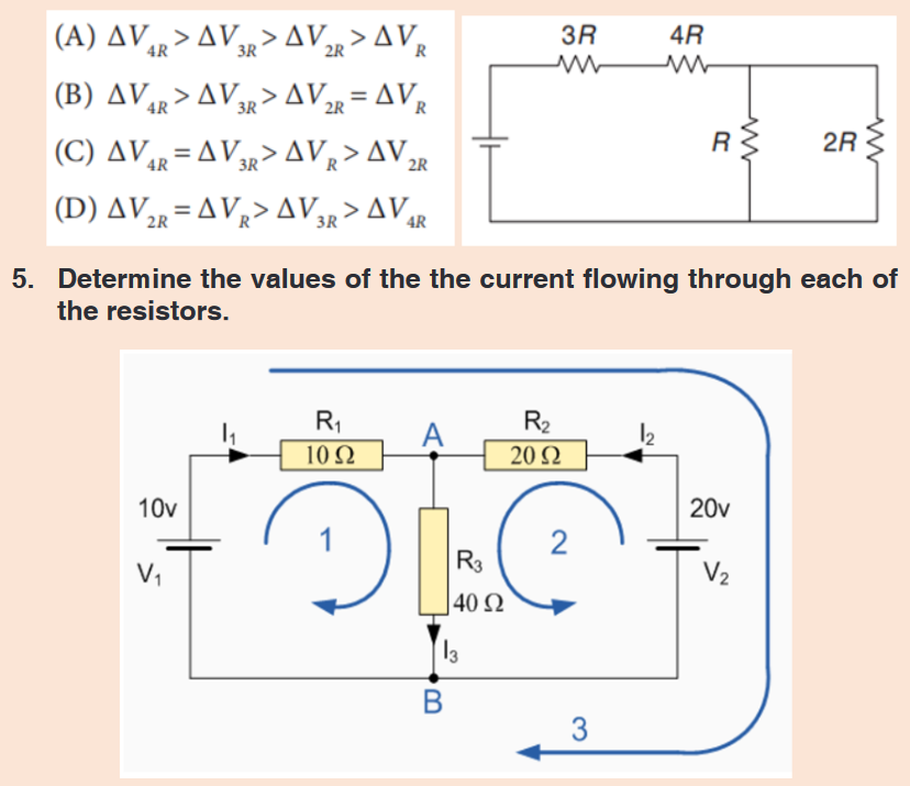
4. The figure below shows four resistors connected in a circuit with a
battery.Which of the following correctly ranks the potential difference,
across the four resistors?