Topic outline
General
- Physics S2 File Uploaded 13/07/21, 14:13
- S2 Physics TG File Uploaded 1/08/22, 22:42
- Heat Transfer and Quantity of heat URL
UNIT 1 Sources of Errors in Measurement of Physical Quantities
URL: 1Labels: 14Quizzes: 21Files: 2Unit 14 Reflection of light in curved mirrors
Key unit competence
The learner should be able to identify and explain the applications of reflected light.My goals
By the end of this unit, I will be able to: identify reflection of light in plane mirrors.
state the laws of reflection of light in plane mirrors.
explain the terms used in curved mirrors.
describe the formation of images by spherical mirrors.
list the applications of spherical mirrors.
establish the images formed by curved mirrors.
locate by construction images formed in curved mirrors and state their characteristics.
perform an experiment to determine the focal length of spherical mirrors.
evaluate images formed by curved mirrors.
discuss applications of curved mirrors.
solve problems related to curved mirrors.
recognise and describe the applications of reflection of light in curved mirrors.
list the applications of plane-curved mirrors.Key concepts
1. How do you draw an image formed by a plane mirror?
2. What do you understand by the term spherical/ curved mirror?
3. How to make a ray diagram of an image formed by a curved mirror.
4. Describe the characteristics of an image formed by a curved mirror.
5. What are different applications of curved mirrors in real life?Vocabulary
Concave mirror, convex mirror, radius of curvature, focal length, pole,
aperture, principal axis, centre of curvature, real and virtual image.Reading strategy
As you read this section, pay attention to key words/terms. Align them with
diagrams and compare them with real life mirror objects you see in the community.Perform calculations related to the spherical mirror as well as making drawings.
Reading strategy
As you read this section, pay attention to key words/terms.Align them with diagrams and compare them with real life mirror objects you see in the
community. Perform calculations related to the spherical mirror as well as making drawings.14.1 Recall reflection of light in plane mirrors
Activity 14.1: Bouncing back of light by the mirror
When light hits a smooth surface, it always bounces back at a matching
angle. To see how this works, try this test. (Fig.14.1)Materials:
⚫ a large plane mirror,
⚫ two cardboard tubes,
⚫ a flashlight,
⚫ some objects.Procedure:
1. Use some objects like a book, bricks etc to prop the mirror upright.
2. Hold one tube at an angle with the end touching the mirror.
3. Ask a friend to hold the second tube at a matching angle.
4. Shine the flashlight into the tube you are holding.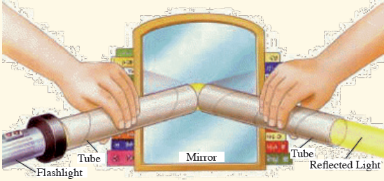
Fig. 14.1: Reflection of light with a mirror
Questions:
1. Explain and discuss your observations.
2. Where are mirrors useful?14.1.1 Plane Mirrors
Mirrors are smooth reflecting surfaces, usually made of polished metal
or glass that has been coated with a metallic substance. As you know,
even an uncoated material can act as a mirror, however, when one side
of a piece of glass is coated with a compound such as tin or silver, its
reflectivity is increased and light is not transmitted through the coating. A
mirror may be front coated or back coated depending on the application.
A mirror with a flat surface is called a plane mirror.14.1.2 Images Formed in Plane Mirrors
When we view an object directly, light comes to our eyes straight from the
object. When we view an object with an optical system, our eyes perceive
light that seems to come straight from the object but whose path has
actually been altered. As a result we see an image that may be different in
size, orientation or apparent position from the actual object.In some cases, light actually comes from the image to our eyes; the image
is then called a real image. In other cases light only appears to come from
the image location; the image is then called a virtual image.Note: A real image is one which can be produced on a screen while
a virtual image cannot be formed on a screen.Rays from the object at O are reflected according to the Laws of reflection
so that they appear to come from point I behind the mirror and this is
where the observer imagines the image to be. The image at I is called a
virtual image because the rays of light do not actually pass through it, they
only seem to come from it.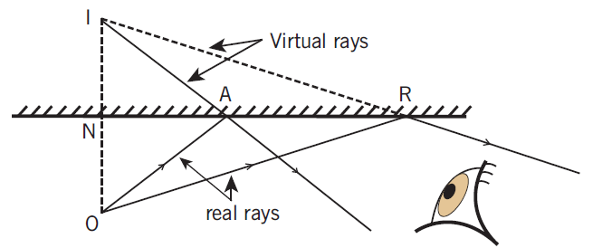
Fig. 14.2: Formation of an image on a plane mirror
It is possible for a plane mirror to give a real image. In Fig. 14.3 below,
a converging beam is reflected so that the reflected rays actually pass
through a point I infront of the mirror. There is a real image at I which can
be picked up on a screen. At the point O, towards which the incident beam
was converging before it was intercepted by the mirror, there is considered
to be a virtual object.
Fig. 14.3: (a) Shows that converging beams from a big object
give a virtual point object O and a real Image I. (b) Shows that
a divergent beam from a real point object gives a virtual point image.The distance of an object from a mirror is called the object distance (dO) and the distance the image appears to be behind the mirror is called the image distance (di). By geometry of similar triangles it can be shown that dO = di. Therefore the image formed by a plane mirror appears to be at a distance behind the mirror that is equal to the distance of the object infront of the mirror. In other words, object and image are equidistant from the mirror.
14.2 Curved mirrors
Activity 14.2: Reflection in spherical mirrorMaterials:
⚫ Concave mirror (s)
⚫ Convex mirror (s)
⚫ An object like a candleProcedures:
⚫ Observe the images of your objects (candle) using given mirrors.
⚫ Move the candle near by the mirror or far from the mirror and
observe the changes on its images.Questions:
1. What happens to the image of the candle as it moves near to the curved mirror?
2. What happens to the image of the candle as it moves far from the curved mirror?
3. Discuss other cases where you observe such situations.We shall consider specifically curved mirrors which have a spherical shape.
Such mirrors are called spherical mirrors. Depending on the side coated,
front or back, the two types of spherical mirrors are concave and convex,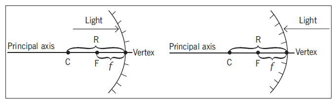
Fig. 14.4: Concave Mirror and Convex Mirror
Spherical mirrors can be thought of as a portion of a sphere which was
sliced and then coated on one side to create a reflective surface. Concave
mirrors are coated on the outside of the sphere while convex mirrors are
coated on the inside of the sphere.14.2.1 Terms and Definitions
⚫ Centre of curvature (C) is the point in the centre of the sphere from which the mirror was sliced.For concave mirrors, the centre C, of the sphere is infront of the reflecting surface.
For a convex mirror, C is behind the reflecting surface.
⚫ Vertex is the point on the mirror surface where the principal axis meets the mirror.The vertex is also known as the pole. The vertex is the geometric center of the mirror.
⚫ Focal point (F) is the point midway between the vertex and centre of curvature.It is also called the “principal focus”.
⚫ Radius of curvature(R) is the distance between the centre of the curvature and the vertex.It is the radius of the sphere from which the mirror was cut.
⚫ Focal length (f) is the distance from the mirror to the focal point.
⚫ Aperture is the surface of the mirror.
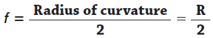
Since the focal point (F) is the mid-point of the line segment joining the
vertex and the centre of curvature, the focal length (f) would be half the radius of curvature.
A narrow beam of rays parallel and near the principal axis is reflected from a concave mirror so that all rays converge on the focal point.
Concave mirrors are also known as converging mirrors because of their action on the parallel beams of light.
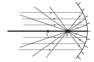
Fig. 14.5: Rays parallel to the principal axis of the concave mirror
A narrow beam of parallel light rays near the principal axis of a convex
mirror are reflected to form a diverging beam which appears to come from
the focal point (F) behind the mirror.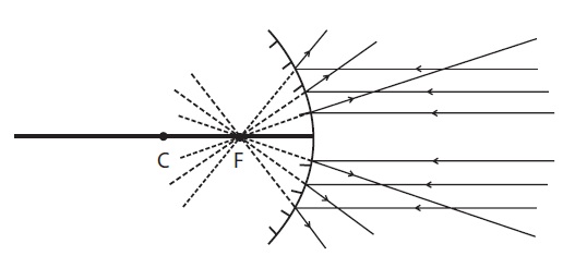
Fig. 14.6: Rays parallel to the principal axis of a convex mirror
14.2.2 Reflection of Light and Image Formation
Light always follows the laws of reflection, whether reflection occurs off
a curved surface or flat surface. For a spherical mirror, the normal at the
point of incidence on the mirror surface is a line that extends through the
centre of curvature. Once the normal is drawn, the angle of incidence can
be measured and the reflected ray can be drawn with the same angle.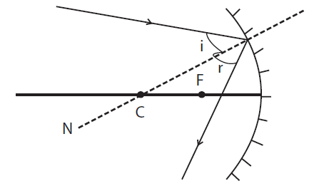
Fig. 14.7: Ray non-parallel to the principal axis of the curved mirror
In general the position of the image formed by spherical mirror and
its nature, i.e. whether it is real, virtual (imaginary), inverted, upright,
magnified or diminished (reduced), depends on the distance of the object
from the mirror. Information about the image can be obtained by either
drawing a ray diagram or by calculating using a formula.14.2.3 Ray Diagrams
Activity 14.3: Investigating the ray diagram of an imageMaterials:
⚫ Concave mirror(s)
⚫ Convex mirror(s)
⚫ Candle(s)
⚫ Lens holder
⚫ White cardboard (screen).Procedure:
⚫ Fix the concave or the convex mirror in a lens holder.
⚫ Put the lighted candle and distance X (infront of the reflecting surface of the mirror).
⚫ On the same side, put the screen in different positions until you get an image.Questions:
1. Try to note your observations discuss and explain them.
2. What is the nature of the image obtained?
3. Comment and explain where the concave and convex mirrors are used in real life.We shall assume that a small object on the principal axis of mirrors of a small aperture are being considered and that all rays are paraxial (i.e. nearly parallel to the axis). Point images will therefore be formed of points
on the object. To construct the image, two of the following three rays are drawn from the top of the object:1. A ray parallel to the principal axis which after reflection actually
passes through the focal point or appears to diverge from the focal point.
Fig. 14.8: Rays reflecting through the main focus
2. A ray through the centre of the curvature which strikes the mirror
normally and is reflected along the same path.

Fig. 14.9: Rays passing through the center of curvature
3. A ray through the principal axis at the focal point which is
reflected parallel to the principal axis, i.e. a ray taking the reverse path of (1).
Fig. 14.10: Rays passing through the main focus
14.2.4 Image characteristics of Concave Mirrors
Case 1: The object (O) is located beyond the centre of curvature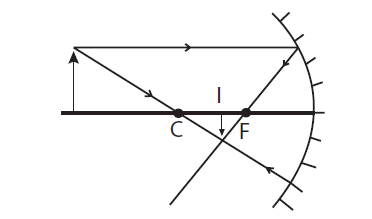
Fig. 14.11: Image of an object placed beyond C
The image (I) is located between C and F, it is real, inverted and diminished.
Case 2: The object (O) is located at the centre of curvature

Fig. 14.12: Object placed at C
The image (I) is located at C, it is real, inverted and the same size.
Case 3: The object (O) is located between C and F.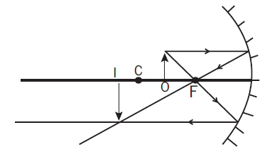
Fig. 14.13: Image of an object placed between C and F
The image (I) is located beyond C, it is real, inverted and magnified.
Case 4: The object (O) is located between the focal point and vertex.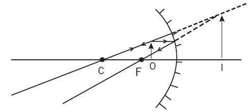
Fig. 14.14: Image given by a convex mirror
The image (I) is located behind the mirror, it is virtual, upright and magnified.
Case 5: The object (O) is located at the focal point.
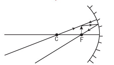
Fig. 14.15: Image of an object placed at F is found at infinity
The image is located at infinity because the reflected rays are parallel.Notes:
(i) In cases 1 and 3, the object and image are
interchangeable. Such positions are called conjugate points.
(ii) C is a self conjugate as case 2 shows the object and image are both at C.
(iii) An object at infinity, i.e. a long way off, forms a real image at F.Conversely an object at F gives an image at infinity.
(iv) In all cases the foot of the object is on the principal axis and its image also is on the principal axis.14.2.5 Image characteristics for Convex Mirrors
Consider different positions of the object (O):
The image (I) for the convex mirror is always located between F and thevertex, it is virtual, upright and diminished.
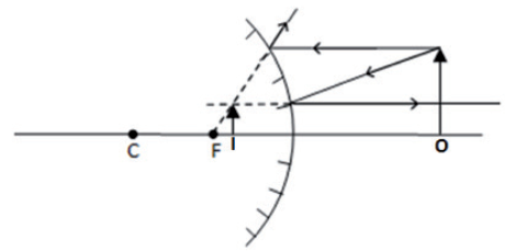
Fig. 14.16: Image characteristic for a convex mirror
14.3 Uses of spherical mirrors
Concave mirrors are used as reflectors in car headlamps and search lights
and are essential components of large telescopes. Convex mirrors give a
wider field of view than a plane mirror. Therefore, they are used as car wing
mirrors, for safety on sharp bends in the road, for security in shops and on
the stairs of double-decker buses. Convex mirrors make the estimation of
distances more difficult because large movements of the object result in
small movement of the image.14.4 The mirror and magnification equations
Ray diagrams can be used to determine the image location, size, orientation
and type of image formed of objects placed at a given location infront
of concave and convex mirrors. Ray diagrams provide useful information
about the object/image relationships, but do not provide quantitative
solutions. To obtain quantitative information it is necessary to use the
mirror equation and the magnification equation.The mirror equation expresses the quantitative relationship between object
distance (do), image distance (di), and the focal length (f).The mirror equation is:
Since R = 2f, the mirror equation can be re-written in terms of the radius
of the curvature (R):
The mirror equation can also be re-written as:

The magnification equation relates the ratio of image distance to object
distance and the ratio of image height to object height.
The minus sign is inserted for a sign convention to indicates orientation of the image.
Sign conventions for mirror and magnification equations.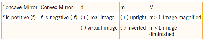
Notes:
(i) A real image is on the same side of the mirror as the object.
(ii) A virtual image is on the opposite side of the mirror from object.
(iii) When determining whether an image is magnified or diminished
do not consider the sign of the magnification. The sign is only used to
determine whether the image is upright or inverted (i.e. m = –3 and m
= 3 both mean the image is magnified 3 times but m = –3 means the
image is inverted (–m) and m = 3 means the image is upright (+m).Activity 14.4: To measure the focal length of a concave mirror
Make a practical activity related to the Fig. 14.17. The Teacher may
assist you to set up such a system.)Materials:
⚫ Concave mirror ⚫ Optical pin (2)
Learning Outcomes:
I should understand the following terms:
⚫ Concave mirror ⚫ Focal point
⚫ Radius of curvatureSometimes the image is a little difficult to find, but this can usually be
overcome by making quite sure that the principal axis of the mirror passes
through the tip of the object pin.In experiments of this type, one must resist a natural inclination to look
into the mirror. The eye should be fixed on the pin, and the image will be
seen to move backwards and forwards as the pin is moved to and fro. The
pin is halted just when the image is exactly above it.Hence, if do and di are measured, we can calculate f two pins are required,
one to act as an object and the other as a search pin. The object pin is
placed infront of the mirror between F and C so that a magnified real
image is formed beyond C. The search pin is then placed so that there is
no parallax between it and the real image (Fig. 14.17).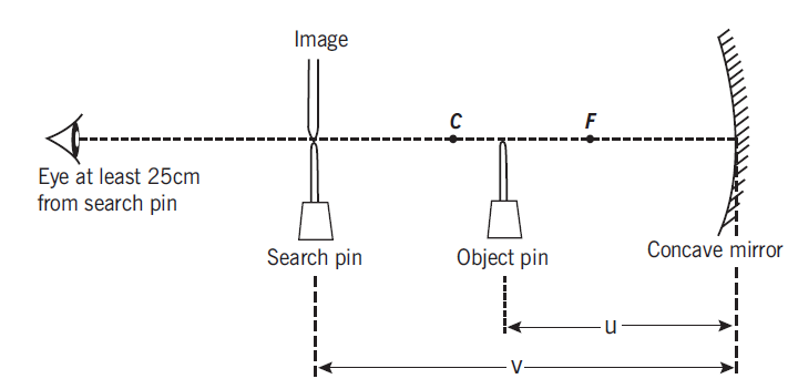
Fig. 14.17: The U and V methods
Activity 14.5: To find the focal length of a convex mirror using a convex mirror
Make a practical activity related to the Fig. 14.18; The teacher may
assist you to set up such a system.Materials:
⚫ Convex mirror ⚫ Optical pin
Learning Outcomes:
I should understand the following terms:
⚫ Convex mirror ⚫ Focal point
⚫ Radius of curvatureA convex mirror is a curved mirror in which the reflecting surface bulges
towards the light source. Convex mirrors reflect light outwards; therefore
they are not used to focus light. A convex mirror is also known as a fish
eye mirror or diverging mirror.The image formed by a convex lens is virtual and erect, since the focal
point (F) and the centre of curvature (2F) are both imaginary points
"inside" the mirror that cannot be reached. As a result, images formed by
these mirrors cannot be projected on a screen, since the image is inside
the mirror. Therefore, its focal length cannot be determined directly. The
image is smaller than the object, but gets larger as the object approaches
the mirror. The ray diagram of a convex mirror is shown below.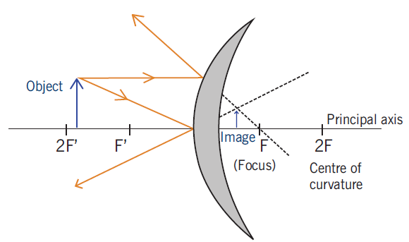
Fig. 14.18: Measuring the focal length of a convex mirror
The focal length f of the convex mirror is calculated using the formula,
14.5 Other types of curved mirrors
14.5.1 Parabolic mirrors
A parabolic mirror (or parabolic reflector) has a reflective surface used to
collect or project light. Its shape is that of a circular paraboloid, that is,
the surface generated by a parabola revolving around its axis.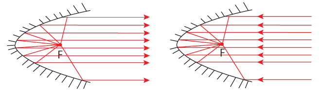
Fig. 14.19: Parabolic mirrors
Any incoming ray that is parallel to the axis of the dish will be reflected
to the focal point, or “focus”. Because light can be reflected in this way,
parabolic reflectors can be used to collect and concentrate light entering
the reflector at a particular angle. Similarly, light radiating from the
“focus” to the dish can be transmitted outward in a beam that is parallel
to the axis of the dish. In contrast with spherical reflectors, which suffer
from a spherical aberration, the parabolic reflectors can be made to
accommodate beams of any width. However, if the incoming beam makesa non-zero angle with the axis (or if the emitting point source is not placed
in the focus), parabolic reflectors suffer from an aberration called coma.
The most common modern applications of the parabolic reflector are in
satellite dishes, reflecting telescopes, and many lighting devices such
as spotlights, car headlights etc.14.5.2 The Ellipsoidal mirror
Ellipsoidal mirrors have two conjugate foci (but in this case the focus
is a geometric point commonly for any ellipsoid). Light from one focus
passes through the other focus after reflection. Ellipsoids collect a much
higher fraction of total emitted light than a spherical mirror or conventional
lens system. The ellipsoidal mirror is the most efficient optics element of
introducing the light that there was from one point into another point.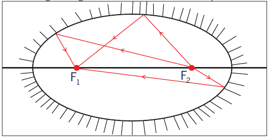
Fig. 14.20: The Ellipsoidal mirror
14.6 Unit 14 assessment
1. Consider the diagram at the right. Which one of the angles (A, B,
C, or D) is the angle of incidence? ______which one of the angles is the angle of reflection? ______
2. A ray of light is incident towards a plane mirror at an angle of
300 with the mirror surface. What will be the angle of reflection?3. A ray of light is approaching a set of three mirrors as shown in
the diagram. The light ray is approaching the first mirror at an
angle of 450 with the mirror surface. Trace the path of the light
ray as it bounces off the mirror. Continue tracing the ray until it
finally exits from the mirror system. How many times will the ray
reflect before it finally exits?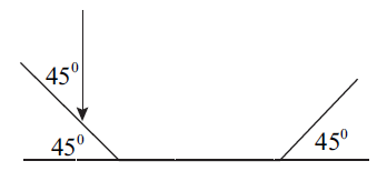
4. Draw a ray diagram to show that a vertical mirror need not
be 1.60m long in order that a woman 1.60m tall may see a
full-length image of herself in it. If the man’s eyes are 10cm
below the top of her head, find the shortest length of the mirror
necessary and the length of its base above floor level.5. A concave spherical mirror has a focal length of 10.0cm. Locate
the image of a pencil that is placed upright 30.0cm from the mirror.
a) Find the magnification of the image.
b) Draw a ray diagram to confirm your answer.6. An upright pencil is placed 10.0cm from a convex spherical
mirror with a focal length of 8.00cm. Find the position and the magnification of the image.7. An object is placed (a) 20cm, (b) 4cm, infront of a concave
mirror of focal length 12cm. Find the nature and the position of the image formed in each case.8. A concave mirror produces a real image 1cm tall of an object
2.5mm tall placed 5cm from the mirror. Find the position of the image and the focal length of the mirror.9. A convex mirror of focal length 18cm produces an image on its
axis, 6cm away from the mirror. Calculate the position of the object.10. A 1.5cm high diamond ring is placed 20.0cm from a concave
mirror whose radius of curvature is 30.0cm. Determine:
a) The position of the image, and its size.
b) Where the new image will be if the object is placed where the image is.11. An object of height h = 4cm is placed a distance p = 15cm
infront of a concave mirror of focal length f = 20cm.
a) What is the height, location, and nature of the image?
b) Suppose that the object is moved to a new position a distance p
= 25cm infront of the mirror. What now is the height, location, and nature of the image?12. A dental technician uses a small mirror that gives a magnification
of 4.0 when it is held 0.60cm from a tooth. What is the radius of the curvature of the mirror?13. A meter stick lies along the optical axis of a convex mirror of focal
length 40cm, with its near end 60cm from the mirror surface.
Five-centimeter toy figures stand erect on both the near and far ends of the meter stick.
a) How long is the virtual image of the meter stick?
b) How tall are the toy figures in the image, and are they erect or inverted?14. How far must an object be placed infront of a convex mirror of radius of curvature R = 50cm in order to ensure that the size of the image is ten times less than the size of the object? How far behind the mirror is the image located?