UNIT 5: DATABASE Basics
5.0 INTRODUCTORY ACTIVITY 5.1: Introduction to Database
 5.1.1 Definition of Database
A database is an organized collection of related data.
It is considered to be organized because the data is stored in categories that are accessible in
a logical manner. A database is a collection of one or more relations, where each relation is atable made of rows and columns.5.1.2 Definition of Data and Information Data is commonly referred to as ‘raw’ data: a collection of text, numbers and symbols,images with no meaning.Data therefore has to be processed, or provided with a context, before it can have meaning.
 Information is the result of processing data, usually by computer.This results in facts, which enables the processed data to be used in context and havemeaning. Information is data that has meaning.Note: An information system is a combination of computer hardware and software that isdesigned to create, store, process and present information. The heart of all informationsystems is a database.
 5.2 Database Approach
 The most efficient way to store data is with the help of a database. A database is made up oftables that contain columns and rows. Each category is given its's own table.For example: a company may have a table for customer information and another for salesnumbers. You can think of a table somewhat like a spreadsheet. Inside a spreadsheet thereare columns and rows of data. For a database however each row is called a record and eachcell is called a field.5.2.1: Traditional File Processing Systems (TFP) approachThis is an approach which was used earlier, prior to DBMS. With this approach, users had towrite their application programs to store data in form of files on the computer permanentstorage device (Hard Disk). A user must have knowledge of programming languages but thisis not easy for a common computer user, even an experienced programmer would find itdifficult to write a program each time a new database was to be created. Each applicationprogram written by a user had to define and manage its own data.a. Advantages of the Traditional File ProcessingCompared to manual management of information, the Traditional File Processing presentsthe following advantages:
 Simplicity: the design of file processing is more simple than designing Database
 Efficiency: file processing cost less and can be more speed than Database
 Customization: you can customize file processing more easily and efficiently thanDatabase because files are related with the application and it have all the data neededfor that application.b. Disadvantages of Traditional File Processing System
 Separation and Isolation of Data: In file-based approach, data are isolated in separate
files.Hence it is difficult to access it.
Separation and Isolation of Data: In file-based approach, data are isolated in separate
files.Hence it is difficult to access it.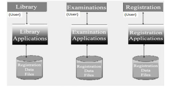

 Duplication of Data: Duplication of data means same data being stored more than
once. This can also be termed as data redundancy.
 Wastage of storage space: Duplication of data leads to wastage of storage space.
If the storage space is wasted it will have a direct impact on cost. The cost will increase.
 Loss of data integrity: Data integrity means that the data contained in the database is
both accurate and consistent (Data inconsistency means different copies of the same
data will have different values).
 Data Dependence: In traditional file processing, the structure of data files is
embedded in the application programs, so any changes to the structure of a file may
require changing all programs that access this file.
 Security problems: File based approach is not secured because different files are
stored in different locations
5.2.2 Database Management System (DBMS)
The Database Management system (DBMS) is a referred to as a software system that is used
to store, access, manage, organize, maintain, modify and delete data from databases. Some
of the most popular software include, Microsoft Access, Oracle, Microsoft SQL Server,
MySQL.
MySQL is, one of the most popular database management systems used by online
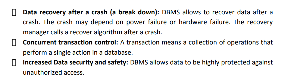
entrepreneurs.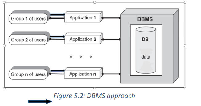 a. The advantages of database management systemThere are many advantages of database management system.
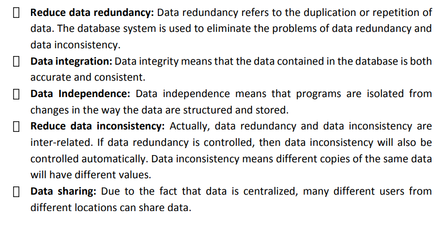
 5.3 Area where database can be applied
 The purpose of the three-level architecture is to separate the user application and the physicalThese days, the evolution of Database management systems has obliged governments, NGOs,and private companies to use databases in their daily basics. They are getting more from theirwork because they can keep records of everything.Database management systems make these organizations work faster to search forinformation and records about any people or products that make them more effective inwork. Below are some of the applications and uses of the database management system(DBMS).
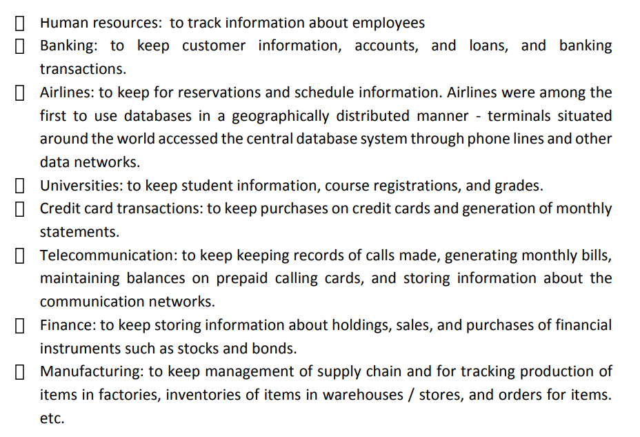
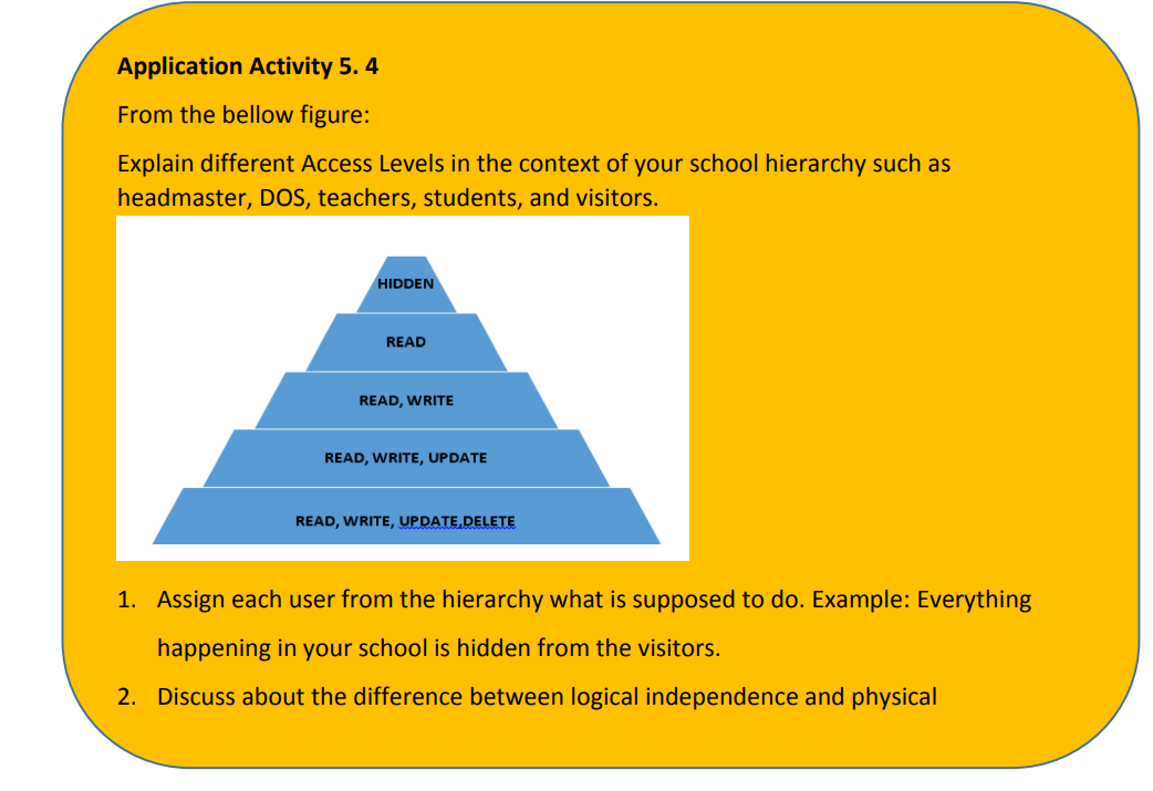
 5.4 Database Access Levels and Users
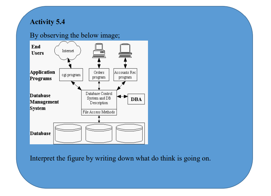 5.4.1 Database access levelsA major purpose of a database system is to provide users with an abstract view of the data.That is, the system hides certain details of how the data are stored and maintained.There are three-levels that form the basis of modern database architectures:a. The Internal LevelThe Internal level has an internal schema, which describes the physical storage structure ofthe database. The internal schema uses a physical data model and describes the completedetails of data storage and access paths for the database.b. The conceptual levelThe conceptual level has a conceptual schema, which describes the structure of the wholedatabase for a community of users.The conceptual schema hides the details of physical storage structures and concentrates ondescribing entities, data types, relationships, user operations, and constraints.Usually, a representational data model is used to describe the conceptual schema when adatabase system is implemented. This implementation conceptual schema is often based ona conceptual schema design in a high-level data model.c. The external or view level:The external view level is closest to the users. It is concerned with the way the data is viewedby individual users. A user can either be an application programmer or an end-user. Theexternal level consists of many different external views of database.At the view level, computer users see a set of application programs that hide details of thedata types.
5.4.2 Database users
database. The reasons of this separation are that different users need different views of the
same data.
1. Users should not have to deal directly with the physical database storage details.
2. The database administrator should be able to change the database storage structure
or storage device without affecting other user's views.
When considering users of a Database system, there are three broad classes to consider:
1. The database administrator (DBA): Responsible for authorizing access to the
database, for coordinating and monitoring its use, acquiring software and hardware
resources, controlling its use and monitoring efficiency of operations.
2. The database designer: Responsible to define the content, the structure, the
constraints, and functions or transactions against the database. They must
communicate with the end-users and understand their needs.
3. The end-user, who accesses: End-users, they use the data for queries, reports and
some of them update the database content.
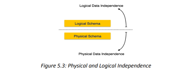
5.4.3 Data Independence
Data Independence: The ability to modify a scheme definition in one level without affecting
a scheme definition in a higher level is called data independence.
There are two kinds:
1. Logical data independence
The ability to modify the conceptual scheme without causing application programs to be
rewritten.
Immunity of external schemas to changes in the conceptual schema usually done when logical
structure of database is altered.
2. Physical data independence
The ability to modify the internal scheme without having to change the conceptual or external
schemas.Modifications at this level are usually to improve performance.
5.5 Relational Model
 5.5.1 Definition of Relational Database Model
The Relational Database Model represents the database as a collection of relations.A relation is nothing but a table of values.
 Every row in the table represents a collection of related data values.
 These rows in the table denote a real-world entity or relationship.
 The table name and column names are helpful to interpret the meaning of values ineach row. The data are represented as a set of relations. In the relational model, dataare stored as tables.5.5.2 Relational Model Concepts in DBMS
 Entity is a real-world object that has certain properties called attributes that definethe nature of the entity.
In Relational model an entity is considered as table. Entities are distinguishable, i.e., each
entity in a pair of entities has a property that makes one entity different from the other entity.
Entities consist of attributes that define their characteristic features/properties.
For example: if we consider a black piece entity on a chessboard and a white piece on a
chessboard, they are distinguishable since the color of the black piece and the white pieceare distinguishable.
 Primary Key is also called a primary keyword, is a key (column) in a relational database
that is unique for each record. Foreign Key is a set of attributes (columns) in a table that refers to the primary key of
another table.
 Alternate Keys is a column or group of columns in a table that uniquely identify
every row in that table.
A table can have multiple choices for a primary key but only one can be set as the primarykey. All the keys which are not primary key are called an Alternate Key.
A table has two properties rows and columns. Rows represent records and columns represent Table: In the Relational model, the relation is saved in the table format.
attributes. Table is a named relational database data set that is organized by rows andcolumns.
 Attribute: Each column in a Table. Attributes are the properties which define a relation.
  Constraint: In DBMS is the set of rules that ensures that when an authorized user
modifies the database they do not disturb the data consistency.
 Tuple: It is nothing but a single row of a table, which contains a single record.
 Degree: is the total number of attributes which in the relation is called the degree of
the relation.
 Cardinality: is the total number of rows present in the table.
 Column: The column represents the set of values for a specific attribute.