General
- Physics S5 SB File Uploaded 28/01/22, 13:51
- Physics S5 TG File Uploaded 4/01/24, 11:45
Unit 7: ELECTRIC FIELD POTENTIAL AND GRAVITATIONAL POTENTIAL
Unit 7: ELECTRIC FIELD POTENTIAL AND GRAVITATIONAL POTENTIAL
Topic Area: Motion in fields
Sub-Topic Area: Electric field Potential and Energy
Key unit competence: By the end of this unit, I should be able to analyze electric field potential and gravitational potential.
Unit Objectives:
By the end of this unit, learners will be able to;
◊ list the properties of an electric and gravitational fields and the variation of potentials properly.
◊ explain the working mechanism of a cathode ray tube, TV tubes and computer monitors properly.
◊ explain the everyday applications of electric and magnetic fields.

7.0 INTRODUCTION
Electricity might be leading technological advancement, but its study began with nature. Electrical storms are a very dramatic example of natural phenomena involving electricity. Other examples are found in animals. Some use electricity as a tool for survival – as a weapon (by electric eels) or to sense live food (by platypus and sharks). Animals routinely use electricity to control their bodies. The story of Frankenstein’s monster, brought to life during an electrical storm, was inspired by early experiments where the legs of a dead frog were made to twitch by sending electrical current through them. Today we use electrical technology not just to support our everyday lives in a myriad of ways, but also to diagnose muscle and nerve activity inside the body, and to assist faulty signaling in the body.
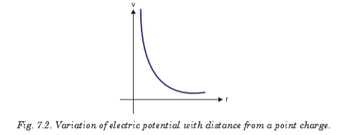
7.1 ELECTRIC FIELD AND ELECTRIC POTENTIAL DUE TO A POINT CHARGE


7.2 ELECTRIC POTENTIAL ENERGY AND POTENTIAL DIFFERENCE
To apply conservation of energy, we first need to define electric potential energy. As we saw in level four, potential energy can be defined only for conservative forces. The work done by a conservative force in moving an object between any two positions is independent of the path taken. The electrostatic force between any two charges is conservative because of its dependence on position just like gravitational force. Hence, we define the potential energy for electrostatic force, assuming potential energy at infinity to be zero as


The potential difference between these two points can be calculated as the difference between their respective electrical potentials as:

7.3 EQUIPOTENTIAL LINES AND SURFACES
The electric potential can be represented by drawing equipotential lines or equipotential surfaces. An equipotential surface is the one on which all points are at the same potential. The potential difference between any two points on the surface is zero, so no work is required to move a charge from one point on the surface to the other. An equipotential surface must be perpendicular to the electric field at any point. If this was not so—that is, if there was a component of
 parallel to the surface—it would
 require work to move the charge along the surface against this component of
; and this would contradict the idea that it is an equipotential surface. The fact that the electric field lines and equipotential surfaces are mutually perpendicular, helps us locate the equipotentials when the electric field lines are known. In a normal two-dimensional drawing, we show equipotential lines, which are the intersections of equipotential surfaces with the plane of the electric field line.
In Fig. 7.5, a few of the equipotential lines are drawn (dashed green lines) for the electric field (red lines) between two parallel plates maintained at a potential difference of 20 V. The negative plate is arbitrarily chosen to be zero volts and the potential of each equipotential line is indicated.
Note that
points towards lower values of V. 7.4 POTENTIAL DUE TO ELECTRIC DIPOLE
The equipotential lines for the case of two equal but oppositely charged particles are shown in Fig. 7.6 as green dashed lines.

Unlike electric field lines, which start and end on electric charges, equipotential lines and surfaces are always continuous curves, and continue beyond the borders indicated in Figs. 7.5 and 7.6.
7.5 CONSERVATION OF ELECTRICAL ENERGY
Energy is conserved in the movement of a charged particle through an electric field, as it is in every other physical situation. Electric charge cannot be created or destroyed (though positive and negative charges can neutralise each other).
Given a stationary test charge at a certain location, an applied electric field will cause the charge to move to one end or the other, depending on the charge.
Positive test charges will move in the direction of the field; negative charges will move in the opposite direction.
At the instant at which the field is applied, the motionless test charge has zero kinetic energy, and its electric potential energy is at the maximum. Now the charge accelerates, and its kinetic energy (due to motion) increases as its potential energy decreases. The sum of energies is always constant.
The formula illustrating conservation of energy can be written in many ways, but all expressions are based on the simple premise of equating the initial and final sums of kinetic (Ekin) and potential (Epot) energy.


7.6 CATHODE RAY TUBE
The CRT is a vacuum tube in which a beam of electrons is accelerated and deflected under the influence of electric or magnetic fields. The electron beam is produced by an assembly called an electron gun located in the neck of the tube. These electrons, if left undisturbed, travel in a straightline path until they strike the front of the CRT, the “screen’’, which is coated with a material that emits visible light when bombarded with electrons.
The operation of a CRT depends on thermionic emission, discovered by Thomas Edison (1847–1931). Consider a voltage applied to two small electrodes inside an evacuated glass “tube” as shown in Fig. 7.7: the cathode is negative, and the anode is positive. If the cathode is heated (usually by an electric current) so that it becomes hot and glowing, it is found that negative charges leave the cathode and flow to the positive anode. These negative charges are now called electrons, but originally they were called cathode rays because they seemed to come from the cathode.
Fig. 7.7 is a simplified sketch of a CRT which is contained in an evacuated glass tube. A beam of electrons, emitted by the heated cathode, is accelerated by the high-voltage anode and passes through a small hole in that anode. The inside of the tube face on the right (the screen) is coated with a fluorescent material that glows at the spot where the electron hits. Voltage applied across the horizontal and vertical deflection plates can be varied to deflect the electron beam to different spots on the screen. The instruments used in the laboratory to display, measure and analyze the waveforms of different circuits is known as cathode ray oscilloscope.

7.7 TV AND COMPUTER MONITORS
In TV and computer monitors, the CRT electron beam sweeps over the screen in the manner shown in Fig. 7.8 by carefully synchronizing voltages applied to the deflection plates. This is called scanning.
During each horizontal sweep of the electron beam, the grid receives a signal voltage that limits the flow of electrons at each instant during the sweep; the more negative the grid voltage is, the more electrons are repelled and fewer pass through, producing a less bright spot on the screen. Thus, the varying grid voltage is responsible for the brightness of each spot on the screen. At the end of each horizontal sweep of the electron beam, the horizontal deflection voltage changes dramatically to bring the beam back to the opposite side of the screen, and the vertical voltage changes slightly so the beam begins a new horizontal sweep slightly below the previous one. The difference in brightness of the spots on the screen forms the “picture”.
Color screens have red, green, and blue phosphors which glow when struck by the electron beam. The various brightnesses of adjacent red, green and blue phosphors (so close together we don’t distinguish them) produce almost any colour. With 30 new frames or pictures every second (25 in countries with 50-Hz line voltage), a “moving picture” is displayed on the TV screen. The commercial movies present 24 frames per second as the film runs.

7.8 TRAJECTORY OF A CHARGE MOVING IN A CATHODE RAY TUBE
If electrons enter an electric field in a CRT acting at right angles to their direction of motion, they are deflected from their original path. In Fig. 7.9, a p.d is applied between the plates P and Q of length l, creates an electric field of intensity E. Consider an electron of charge e, mass m and velocity v entering the field.


EXAMPLE 7.1
A beam of electrons moving with velocity 1 × 10⁷ m/s enters mid-way between two horizontal parallel plates P and Q in a direction parallel to the plates as shown on Fig.7-10. P and Q are 5 cm long and 2 cm apart, and have a p.dV applied between them.


1. Fig. 7.11 shows two metal plates 2.0 cm long placed 5 mm apart. A fluorescent screen is placed 20.0 cm from one of the plates. An electron of kinetic energy 3.2 × 10⁻⁶ J is incident mid-way between the plates. Calculate the voltage applied across the plates to deflect the electron 2.1 cm on the screen. Assume that the electron moves through vacuum.

2. In the diagram of Fig. 7.12, P and Q are parallel metal plates each of length l = 4 cm. A p.d of 12V is applied between P and Q. The space between P and Q is virtual. A beam of electrons of speed 1.0 × 10⁶ m/s is directed mid-way between P and Q at right angles to the electric field between P and Q. Show that the electron beam emerges from the space between P and Q at an angle of 64.6° to the initial direction of the beam.

7.9 ELECTRODYNAMICS
This is the study of phenomena associated with charged bodies in motion and varying electric and magnetic fields. Since a moving charge produces a magnetic field, electrodynamics is concerned with effects such as magnetism, electromagnetic radiation and electromagnetic induction, including some practical applications as the electric generator and the electric motor.
This area of electrodynamics, often known as classical electrodynamics, was first systematically explained by the physicist James Clarke Maxwell. Maxwell’s equations, a set of differential equations, describe the phenomena of this area with great generality. A more recent development is quantum electrodynamics, which was formulated to explain the interaction of electromagnetic radiation with matter, to which the laws of the quantum theory apply.
When the velocities of the charged particles under consideration become comparable with the speed of light, corrections involving the theory of relativity must be made; this branch of the theory is called relativistic electrodynamics. It is applied to phenomena involved with particle accelerators and with electron tubes that are subject to high voltages and carry heavy currents.
7.10 GRAVITATIONAL FIELD AND GRAVITATIONAL POTENTIAL


Let Me be the mass of the earth;
The force of attraction between the earth and the mass m is:

Where r is the distance of the mass from the center of the earth. The work done by gravitational force in moving a mass through a distance dr towards the earth is:

Since we are considering a unit mass, m = 1 kg

So the total work done in moving a unit mass from infinity to a point located at distance R from the center of the earth is obtained by integration:

The negative sign indicates that potential at infinity is higher than potential at a point closer to the centre of the earth.
7.11 ESCAPE VELOCITY FOR A PLANET
If the rocket is fired from the surface of the earth with velocity v such that
it just escapes from the influence of the earth’s gravitational pull, then this velocity is called escape velocity.
Work done W.d. on a mass m at the surface of the earth of mass Me and radius Re is:

From work energy theorem, this work done equals the kinetic energy of the rocket as it escapes from the earth’s surface.

When the object of mass m is on the surface of the earth, the gravitational force equals the weight of the object;

This time the distance r equals the radius of the earth Re. This gives;

Notes
With an initial velocity about 11 km/s, a rocket will completely escape from the gravitational attraction of the earth and the velocity is independent of the mass of the rocket.
7.12 ENERGY CONSERVATION IN GRAVITATIONAL FIELDS
Conservation of energy tells us that the total energy of the system is conserved, and in this case, the sum of kinetic and potential energy must be constant. This means that every change in the kinetic energy of a system must be accompanied by an equal but opposite change in the potential energy.
Satellites have kinetic energy due to their motion and potential energy due to their position with respect to the center of the earth. A satellite of mass m in orbit round the earth moving at a velocity v has kinetic energy. If the satellite is circling the earth at a radius r it has a centripetal force which balances with gravitational force of attraction with which the earth is attracting the satellite. If Me is the mass of the earth,


