Topic outline
General
- Physics S5 SB File Uploaded 28/01/22, 13:51
- Physics S5 TG File Uploaded 4/01/24, 11:45
Unit 1: WAVE AND PARTICLE NATURE OF LIGHT
Unit 1: WAVE AND PARTICLE NATURE OF LIGHT
Topic Area: LIGHT
Sub-Topic Area: Wave Particle Duality
Key unit competence: By the end of the unit, I should be able to analyze the nature of light.
Unit Objectives:
By the end of this unit learners will be able to;
◊ Explain the Planck’s quantum theory and apply it to other theories.
◊ Explain photoelectric effect and use it to derive and apply
Einstein’s photoelectric equation
◊ explain photoelectric effect and use it to derive and apply
Einstein’s photoelectric equation.
◊ Explain the wave theory of light and state its limitations.
◊ Evaluate properties of light as a wave.
◊ Differentiate electron microscope and Compton Effect as applied in medicine.
1.0 INTRODUCTION
Until the late 19th century physicists used to explain the phenomena in the physical world around them using theories such as mechanics, electromagnetism, thermodynamics and statistical physics that are known as classical theories.
At the turn of the 19th century, more and more experiments showed effects that could not be explained by these classical theories. This indicated a need for a new theory that we now know as quantum mechanics. Quantum mechanics is the system of laws which governs the behaviour of matter on the atomic scale. It is the most successful theory in the history of science, having withstood thousands of experimental tests without a single verifiable exception. So, the quantum mechanics is required to analyze the behaviour of photons, electrons and other particles that make up the universe.
This theory is the most useful in various studies especially for Radiography and Physiotherapy in Medicine, electrons and photons in Chemistry and Astronomy in Geography.
Opening question
Clearly observe the image shown on Fig.1-1, with kids playing on a slide with the help of their father Mr. John and answer the questions that follow.
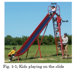
a) Sarah is climbing the ladder. How do you think her potential energy is changing?
b) Comment on the potential energies of Jovia and Peter.
c) How is the change in the potential energy of Jovia as she slides down?
d) What do you think is Mr. John doing on the young kid? Give your comments.
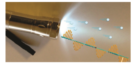
Fig.1.2 below shows how light interacts with an electron. F and B are the terminals of the circuit (the wires of an external circuit).

The working mechanism of Fig.1.2 is used in solar cells and solar panels. Clearly analyse Fig.1.2 and compare it with the situation on Fig.1.1, take children as electrons at different points or positions, and make your comments.
1.1 PLANCK’S QUANTUM THEORY
The quantum theory arose out of the inability of the classical physics to explain the experimentally observed distribution of energy in the spectrum of a blackbody. When a blackbody is heated, it emits thermal radiations of different wavelengths or frequency. To explain these radiations, Max Planck put forward a theory known as Planck’s quantum theory. The theory is summarized in the following statements:
1. The matter is composed of a large number of oscillating particles. These oscillators have different frequencies.
2. The radiant energy which is emitted or absorbed by the blackbody is not continuous but discontinuous in the form of small discrete packets of energy and each such packet of energy is called a ‘quantum’. In case of light, the quantum of energy is called a ‘photon’.
3. The energy of each quantum is directly proportional to the frequency (f) of the radiation, i.e.

whereas c is the speed of light, l is the wavelength and h is the Planck’s constant

4. The oscillator emits energy, when it moves from one quantized state to the other quantized state. The oscillator does not emit energy as long as it remains in one energy state. The total amount of energy emitted or absorbed by a body will be some whole number quanta. Hence,

where n is an integer.
According to the Planck’s theory, the exchange of energy between quantized states is not continuous but discrete. This quantized energy is in small packets of bundles. The bundle of energy or the packet of energy is called quantum (plural quanta).
EXAMPLE 1.1
The laser in a compact disc player. It uses light with a wavelength of
7.8 × 10² nm. Calculate the energy of a single photon of this light.
EXAMPLE 1.2
What is the ratio between the energies of two radiations, one with a wavelength of 200 nm and the other with 600 nm?


EXERCISE 1.1
1. What is quantum mechanics?
2. What is Planck’s quantum theory?
3. Explain Planck’s hypothesis or what are the postulates of Planck’s quantum theory?
4. A laser emits light energy in short pulses with frequency 4.69 × 10¹⁴ Hz and deposits 1.3 × 10⁻² J for each pulse. How many quanta of energy does each pulse deposit?
1.2 PHOTON THEORY OF LIGHT AND PHOTOELECTRIC EFFECT
As proposed by Einstein, light is composed of photons, very small packets of energy. A photon has no mass and no charge. It is a carrier of electromagnetic energy and interacts with other discrete particles, e.g. electrons, atoms and molecules.
A beam of light is modelled as a stream of photons, each carrying a welldefined energy that is dependent upon the wavelength of the light. Einstein reasoned that to conserve energy, the light ought to be emitted in packets or quanta or photons and the energy of a given photon can be calculated by:

where h is the Planck’s constant, c is the speed of light and l is the wavelength.
Because all light ultimately comes from a radiating source, this idea suggests that light is transmitted as tiny particles, or photons as they are now called. The photon theory of light was also a radical departure from classical ideas. Einstein proposed a test of the quantum theory of light:
quantitative measurements on the photoelectric effect.

The emission of electrons from the surface of metals, when light of a certain frequency is incident on it is known as photoelectric effect. In other words, it is the process of the removal of electrons from the surface of metal when the rays of special frequency fall on the surface of metal. As a result of the flow of these photoelectrons, the photoelectric current is produced.
Applications of photoelectric effect
There are numerous desirable applications based on photoelectric effect such as:
Automatic doors — The beam of light strikes the photocell, the photoelectric effect generates enough ejected electrons to produce a defectable electric current. When the light beam is blocked (by a person), the electric current is intruppted and the doors are signaled to open.
Solar panels — Photocells convert sunlight into electrical energy. Some other applications of photoelectric emission are: television, camera, tube light, activated counters, intrusion alarms, turn on street lights at dawn and safety lights.
1.3 WAVE THEORY OF MONOCHROMATIC LIGHT
Till the end of the 19th, century the predominant perception of wave propagation was moduled in some medium. Therefore, a medium called ether, was hypothesized for waves of light. The necessity of hypothesizing ether occured because it is different from any material medium known to us and it arises because light travels through empty space. For example, light coming from the sun and the stars as well as dense objects like glass, diamond can travel through empty space etc. Huygens published this theory in 1690, having compared the behaviour of light not with that of water waves but with that of sound. According to the Huygens’ principle:
• Light travels in the form of longitudinal waves which travel with uniform velocity in homogeneous medium.
• Different colours are due to the different wavelengths of light waves.
• We get the sensation of light when these waves enter our eyes.
• In order to explain the propagation of waves of light through vacuum. Huygens suggested the existence of a hypothetical medium called luminiferous ether, which is present in vacuum as well as in all material objects. Since ether couldn’t be detected, it was attributed properties like:
It is continuous and is made up of elastic particles.
It has zero density.
It is perfectly transparent.
It is present everywhere.
The Huygens’ principle of the wave theory of light states that:
“Every point on a wavefront may be considered a source of secondary spherical wavelets which spread out in the forward direction at the speed of light. The new wavefront is the tangential surface to all of these secondary wavelets.”

In the wave theory assuming monochromatic light, the two important properties of a light wave are its intensity and frequency (or wavelength). When these two quantities are varied, the wave theory makes the following predictions:
1. if the light intensity is increased, the number of electrons ejected and their maximum kinetic energy should be increased because the higher intensity means greater electric field amplitude, and the greater electric field should eject the electrons with higher speed.
2. the frequency of the light should not affect the kinetic energy of the ejected electrons. Only the frequency of incident radiation affect the maximum kinetic energy.
There are, however, at least two problems with this idea and these led Newton and others to reject it:
(a) The secondary waves are propagated in the forward direction only, and
(b) They are assumed to destroy each other except when they form the new wavefront.
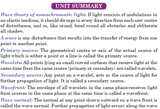
Newton wrote, ‘If light consists of undulations in an elastic medium, it should diverge in every direction from each new centre of disturbance. Like sound bend around all obstacles and obliterate all shadows.’ Newton did not know that in fact light behaves the same, but the effects are exceedingly small due to the very short wavelength of light.
(Huygens’ theory also failed to explain the rectilinear propagation of light.)
Definitions
A wave is any disturbance that results into the transfer of energy from one point to another point.
Primary source: The geometrical centre or axis of the actual source of light which is either a point or a line is called the primary source.
Wavelets: All points lying on small curved surfaces that receive light at the same time from the same source (primary or secondary) are called wavelets.
Secondary source: Any point on a wavelet, acts as the source of light for further propagation of light. It is called a secondary source.
Wavefront: The envelope of all wavelets in the same phase receives light from sources in the same phase at the same time is called a wavefront.
Wave normal: The normal at any point drawn outward on a wavefront is called the wave normal. Further propagation of light occurs along the wave normal. In isotropic media, the wave normal coincides with the ‘ray of light’.
Limitations of Huygens’ wave theory of light
• It could not explain the rectilinear propagation of light.
• It could not explain the phenomena of polarization of light such as Compton effect and Photoelectric effect.
• Michelson and Morley experiment concluded that there is no ether drag when the earth moves through it. This proves ether doesn’t exist. All the other attempts/ experiments to detect Luminiferous ether failed, which prove that it does not exist.
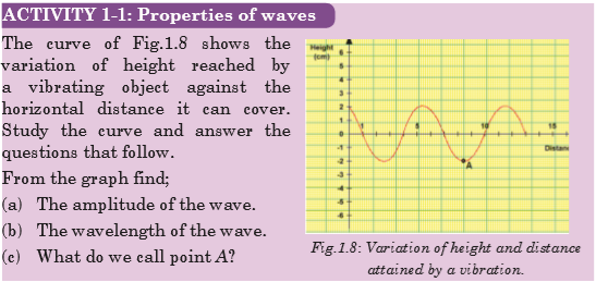
1.4 PROPERTIES OF A LIGHT WAVE
The properties of waves include the following:
The wavelength of a wave is defined as the distance over which the wave’s shape repeats.
It is the distance between the corresponding points on successive cycles, eg. the distance between two wave crests is known as wavelength of a sinusoidal wave. It is measured in units of length (metres, nanometres). The wavelength is usually represented by the symbol
 (lambda).
 A measurement of the wavelength is made by observing the wave in space at a single instant of time.


1.5 BLACK BODY RADIATION
One of the earliest indications that classical physics was incomplete came from attempts to describe blackbody radiation. A blackbody is a theoretical object that absorbs 100% of the radiation that hits it and re-radiates energy which is the characteristic of this radiating system or body only. Therefore, it reflects no radiation and appears perfectly black.
The blackbody radiation is the emission of electromagnetic waves from the surface of an object. The distribution of blackbody radiation depends only the temperature of the object and is independent of the material.
This concept is idealized but can be very nearly realized in practice as illustrated in Fig. 1.9. The inner wall of the enclosure is black so that most of any radiation which enters through the small hole is absorbed on reaching the wall. The small amount of radiation which is reflected has very little chance of escaping through the hole before it is absorbed in a subsequent encounter with the wall.

A blackbody radiator can be made by surrounding the enclosure of
Fig. 1.9(a) with a heating coil as shown on Fig.1.9(b). The radiation which is emitted by any section of the wall is involved in many reflections before it eventually emerges from the hole. Any section which is a poor emitter absorbs very little of the radiation which is incident on it, and those sections which are good emitters absorb most of the radiation which incident on them. This is the effect of mixing the radiations before they emerge and of making the temperature same at all points on the inner surface of the enclosure.
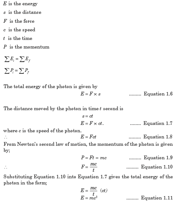
1.6 ENERGY, MASS AND MOMENTUM OF A PHOTON
The famous Einstein equation of energy of the photon is E = mc2. In short, the equation describes how energy and mass are related with speed of light. To derive this equation, consider an X-ray photon of mass m hitting the surface of a metal and consider if a part of its energy is gained by a surface electron and is then emitted as shown in Fig. 1.10.
The most important laws in dynamics are those that state the conservation of energy and the conservation of momentum. These two laws can be applied whenever we have a closed system; that is, a system that does not interact with its surroundings. They assert that for such systems and any process they may undergo:
Assume that;

EXERCISE 1.2
The mass of an electron or positron is 9.11 × 10⁻³¹ kg. The speed of light is 3.0 × 10⁸ m/s.
1. Show that the rest energy of an electron is 8.2 × 10⁻¹⁴J.
2. Use the answer to question 1, to show that the rest energy of an electron is 0.51 MeV.
3. Write down the rest energy of a positron (antielectron).
4. An electron and a positron meet and annihilate one another. By how much does the rest energy decrease in total? Express the answer in MeV.
5. The annihilation of an electron and a positron at rest produces a pair of identical gamma ray photons travelling in opposite directions. Write down (in MeV) the energy you expect each photon to have.
6. A single photon passing near a nucleus can create an electron–positron pair. Their rest energy comes from the energy of the photon. Write down the smallest photon energy that can produce one such pair.
7. Cosmic rays can send high-energy photons through the atmosphere. What approximately is the maximum number of electron–positron pairs that a 10 GeV photon can create?
1.7 COMPTON EFFECT AND PHOTON INTERACTIONS
The Compton Effect concerns the inelastic scattering of X-rays by electrons. Scattering means dispersing in different directions and inelastic means that energy is lost by the scattered object in the process. The intensity of the scattered X-ray is measured as a function of the wavelength shift.
Photons are electromagnetic radiation with zero mass, zero charge, and a velocity that is always equal to the speed of light. Because they are electrically neutral, they do not steadily lose energy via Coulombic interactions with atomic electrons, as charged particles do. Photons travel some considerable distance before undergoing a more “catastrophic” interaction leading to partial or total transfer of the photon energy to electron energy. These electrons will ultimately deposit their energy in the medium. Photons are far more penetrating than charged particles of similar energy. There are many types of photon interactions. We will only discuss those that are important in radiation therapy and/or diagnostic radiology.
1.7.1 Types of photon interactions
Coherent scattering
Coherent scattering is one of three forms of photon interaction which occurs when the energy of the X-ray or gamma photon is small in relation to the ionisation energy of the atom. It therefore occurs with low energy radiation. Upon interacting with the attenuating medium, the photon does not have enough energy to liberate the electron from its bound state (i.e. the photon energy is well below the binding energy of the electron), so no energy transfer occurs. The only change is a change of direction (scatter) of the photon, hence it is called ‘unmodified’ scatter. Coherent scattering is not a major interaction process encountered in radiography at the energies normally used. There are two types of coherent scattering: Thomson scattering and Rayleigh scattering.
• In Thomson scattering, only one electron of the atom is involved in the interaction.
• With Rayleigh scattering, all the electrons of the atom, sometimes called the electron cloud, are involved in a cooperative effort in the interaction with the photon.
Photoelectric effect
The following points make this phenomena clear:
1. The photon must have an energy equal to or greater than the binding energy of electron in the atom.
2. The incident photon must be completely absorbed by the electron.
3. The electron is then ejected from the atom.
4. The excess energy over the binding energy is given to the electron in the form of kinetic energy (which is the speed of the electron).
5. The hole left in the atom is filled by an outer shell electron or a free electron with the emission of characteristic radiation.
Compton interaction
In Compton interaction, the photon interacts with a ‘free’ or an outer shell electron. A portion of incident energy of the photon will be transferred to an electron in the form of kinetic energy. The incident photon, now called a scattered photon will be deflected in a new direction with less energy. Energy given to recoil electron is considered as the absorbed energy and the energy retained by the photon is considered scattered.
Pair Production
The photon interacts with the nuclear field of the atom, in such a way, that the photon transforms itself into an electron-positron pair. As the photon interacts with the strong electric field around the nucleus, it undergoes a change of state and is transformed into two particles (essentially creating matter from energy).
Photo disintegration
(Photo transmutation) It is a nuclear reaction in which the absorption of high energy electromagnetic radiation (a gamma-ray photon) causes the absorbing nucleus to change to another species by ejecting a subatomic particle, such as a proton, neutron, or alpha particle.

1.8 WAVE PARTICLE DUALITY OF LIGHT
When one focusses on different types of phenomena such as interference, diffraction and polarisation, a wave picture of light can be built. This is because these phenomena are also found in properties of waves.
Experiments such as Young’s double slit experiment depend upon the diffraction of light waves and the constructive and destructive interferences show that light has wave-like properties.
The analysis of data in photoelectric experiment showed that the energy of ejected electrons was proportional to the frequency of illuminated light. This showed that whatever was knocking the electrons out had an energy proportional to frequency. The ejection energy of illumination showed that the interaction must be like that of a particle and gave all of its energy to the electron.
This fits well with Planck’s hypothesis that light in the blackbody experiment could exist only in discrete bundles of energy, so we conclude that light is a particle.
1.9 THE PRINCIPLE OF COMPLEMENTARITIES
The principle of complementarities refers to the effects such as wave particle duality in which different measurements made on the system reveal it to have either particle-like or wave-like properties. Both properties are necessary to gain the complete knowledge of the phenomena; they are complementary to each other; but at the same time, they also exclude each other.
Within the scope of classical physics, all characteristic properties of a given object can be ascertained by a single experimental arrangement, although in practice various arrangements are often convenient for the study of different aspects of the phenomena. In fact, data obtained in such a way simply supplement each other and can be combined into a consistent picture of the behaviour of the object under investigation. In quantum physics, however, evidence about atomic objects obtained by different experimental arrangements exhibits a novel kind of complementary relationship.
1.10 THE WAVE NATURE OF MATTER
Being fully aware of the pioneering work of Einstein on the photoelectric effect, de Broglie extended the notion of wave particle duality to matter. All matter can exhibit wave-like behaviour. For example, a beam of electron can be diffracted just like a beam of light or a water wave. The concept that matter behaves like a wave is also referred to de Broglie hypothesis. The de Broglie wavelength is the wavelength, l, associated with a massive particle and is related to its momentum p.

With p being the particle’s momentum. The particles are diffracted by passing through an aperture in a similar manner as light waves. The wave properties of particles mean that when you confine it in a small space its momentum and kinetic energy must increase.
It is important to realize that the attribution of a wavelength to a massive particle implies that it should behave as a wave under some conditions. For example, it should be possible to verify this wave-like behavior when performing a diffraction experiment. Of course, there was no experimental evidence of any sort at the time to justify such an assertion.
To understand how a massive particle could exhibit wave-like properties, or how a wave could ‘behave as a particle, we must first review the notions of phase and group velocities.
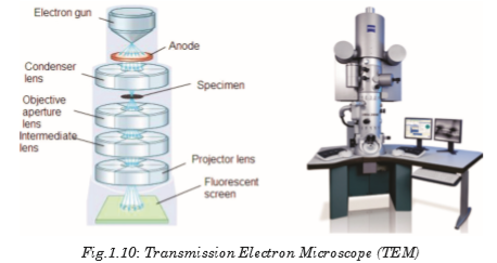
1.11 ELECTRON MICROSCOPE
A microscope can be defined as an instrument that uses one or several lenses to form an enlarged (magnified) image. Microscopes can be classified according to the type of electromagnetic wave employed and whether this wave is transmitted or not through the specimen. The most common electron microscopes are Transmission Electron Microscope (TEM) and Scanning Electron Microscope (SEM).
1.11.1 Transmission electron microscope (TEM)
This is a microscopy technique whereby a beam of electrons is transmitted through an ultra thin specimen, interacting with the specimen as it passes through it. An image is formed from the electrons transmitted through the specimen, magnified and focused by an objective lens. It appears on an imaging screen, a fluorescent screen (in most TEMs), a monitor, or on a layer of photographic film. It can also be detected by a sensor such as a CCD camera. Theoretically, the maximum resolution that one can obtain with a light microscope has been limited by the wavelength of the photons that are being used to probe the sample and the numerical aperture of the system.
TEM consists of a cylindrical tube about 2 metres long. The tube contains vacuum where the specimen is located. This is because the molecules of gases, such as those in air, absorb electrons.
TEM works by emitting electrons from a cathode, then accelerating them through an anode, after which the electrons pass through an aperture into the vacuum tube.
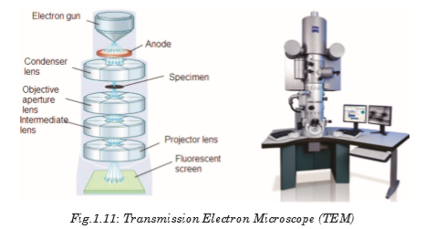
As it passes down through the tube the electron beam is controlled by electromagnetic lenses formed by coils around the tube (whose effect is moderated by adjusting the electricity flowing through the coils). These electromagnetic lenses direct the electron beam through the centre of the tube to a very thin specimen located part-way down the tube.
Some parts of the specimen might allow electrons to pass through them unaffected. Other regions within the specimen absorb some or all of the electrons that reach them. If any electrons continue from that part of the specimen further down the tube to the image formation plane with less energy. This happens because some of their energy has been absorbed by, or “passed to”, the part of the specimen that the electron(s) passed through.
TEM Applications
• TEMs provide topographical, morphological, compositional and crystalline information.
• It is useful in the study of crystals and metals, but also has industrial applications.
• TEMs can be used in semiconductor analysis and the manufacturing of computer and silicon chips.
• Tech giants use TEMs to identify flaws, fractures and damages to micro-sized objects; this data can help and fix problems and/or help to make a more durable efficient product.
• Colleges and universities can utilize TEMs for research and studies.
1.11.2 Scanning Electron Microscope (SEM)
The SEM is designed for direct study of the surfaces of solid objects. By scanning with an electron beam that has been generated and focussed by the operation of the microscope, an image is formed in the same way as a TV.
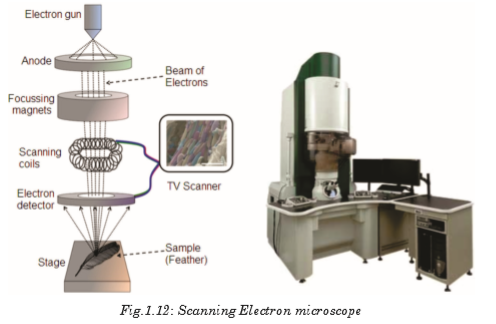
The SEM allows a greater depth of focus than the optical microscope. For this reason, the SEM can produce an image that is a good representation of the three-dimensional sample.
The SEM uses electrons instead of light to form an image. A beam of electrons is produced at the top of the microscope by heating a metallic filament. The electron beam follows a vertical path through the column of the microscope. It makes its way through electromagnetic lenses which focus and direct the beam down towards the sample. Once it hits the sample, other electrons (backscattered or secondary) are ejected from the sample. Detectors collect the secondary or backscattered electrons, and convert them to a signal that is sent to a viewing screen similar to the one in an ordinary television, producing an image. To produce an image on the screen, the electron beam scans over the area to be magnified and transfers this image to the TV screen.
Applications of SEM
• Image morphology of samples (eg. view bulk material, coatings, sectioned material, foils, even grids prepared for transmission electron microscopy).
• Image composition and finding some bonding differences (through contrast and using backscattered electrons).
• Image molecular probes: metals and fluorescent probes.
• Undertake micro and nano lithography: remove material from samples; cut pieces out or remove progressive slices from samples (eg. using a focussed ion beam).
• Heat or cool samples while viewing them (it is generally done only in ESEM or during Cryo-scanning electron microscopy).
• Wet and dry samples while viewing them (only in an ESEM)
• View frozen material (in an SEM with a cryostage)
• Generate X-rays from samples for microanalysis (EDS; WDS) to determine chemical composition.
• Study optoelectronic behaviour of semiconductors using cathodoluminescence
• View/map grain orientation/crystallographic orientation and study related information like heterogeneity and microstrain in flat samples (Electron backscattered diffraction).
• Electron diffraction using electron backscattered diffraction. The geometry may be different from a transmission electron microscope but the physics of Bragg Diffraction is the same.


 URLs: 2Files: 2
Unit 2: SIMPLE HARMONIC MOTION
Unit 2: SIMPLE HARMONIC MOTION
Topic Area: OSCILLATIONS AND WAVES
Sub-Topic Area: ENERGY CHANGES IN SIMPLE HARMONIC MOTION
Key unit competence: By the end of the unit I should be able to analyze energy changes in simple harmonic motion.
Unit Objectives:
By the end of this unit I will be able to;
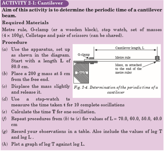
◊ Determine the periodic time of an oscillating mass by practically and by calculation accurately.
◊ Derive and apply the equation of simple harmonic motion correctly
◊ Determine the periodic time of the simple pendulum correctly.
2.0 INTRODUCTION
You are familiar with many examples of repeated motion in your daily life. If an object returns to its original position a number of times, we call its motion repetitive. Typical examples of repetitive motion of the human body are heartbeat and breathing. Many objects move in a repetitive way, such as a swing, a rocking chair and a clock pendulum. Probably the first understanding of repetitive motion grew out of the observations of motion of the sun and phases of the moon.
Strings undergoing repetitive motion are the physical basis of all string musical instruments. What are the common properties of these diverse examples of repetitive motion?
In this unit we will discuss the physical characteristics of repetitive motion and develop techniques that can be used to analyze this motion quantitatively.
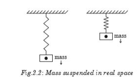
Opening question
Clearly analyze the images of Fig. 2-1 given below and explain what you think will happen in each case when the mass is displaced.

2.1 KINEMATICS OF SIMPLE HARMONIC MOTION
One common characteristic of the motions of the heartbeat, clock pendulum, violin string and the rotating phonograph turntable is that each motion has a well defined time interval for each complete cycle of its motion. Any motion that repeats itself with equal time intervals is called periodic motion. Its period is the time required for one cycle of the motion.
Simple harmonic motion (SHM) is a type of motion where the restoring force is directly proportional to the displacement and acts in the direction opposite to that of displacement.
SHM is an oscillatory motion under a retarding force proportional to the amount of displacement from an equilibrium position. This means that Simple harmonic motion occurs when
• the force F acting on an object is directly proportional to the displacement x from a fixed point and is always towards this point.

• This means that acceleration is directly proportional to displacement from a fixed point and it is always directed towards this point.

Definition of terms
Time Period or Periodic Time T: It is the time taken for the particle to complete one oscillation, that is, the time taken for the particle to move from its starting position and return to its original position and is generally denoted by the symbol T.
Frequency f means how many oscillations occur in one second. Since the time period is the time taken for one oscillation, the frequency is expressed by; (f is frequency in one oscillation and T is the time period)

The frequency is measured in s –1. This unit is known as the hertz (Hz) in honour of the physicist Heinrich Hertz.
Amplitude A is the maximum displacement of the particle from its resting position or mean position.
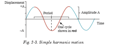
Fig.2-3 shows the displacement-time graph of a periodic motion of a particle. From this graph, displacement can be represented as;

Angular velocity (w): Angular velocity is the rate of change of angular displacement. It is measured in (rad/s). This is related to periodic time according to equation (2-4).

Linear velocity
: Linear velocity is the rate of change of linear displacement. It is measured in (m/s).

Linear acceleration a of a particle is the rate of change of linear velocity of that particle with time. It is measured in m/s2.

2.2 EQUATION OF SIMPLE HARMONIC MOTION
The equation of simple harmonic motion is derived based on the conditions necessary for periodic motion to be simple harmonic.
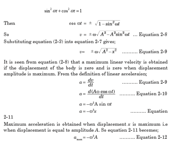
Linear velocity can be related to displacement as shown below:


But from trigonometric identities;


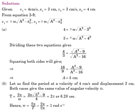
EXAMPLE 2.1
A particle moving with SHM has velocities 4 cm/s and 3 cm/s at distances
3 cm and 4 cm respectively from equilibrium position. Find(a) the amplitude of oscillation
(b) the period
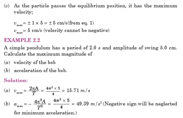
(c) velocity of the particle as it passes through the equilibrium position.
QUESTIONS
(i) Measure the gradient, m of your graph.
(j) Calculate the intercept c on the vertical axis.
(k) Calculate the constant a of the rule from c = log a.
(l) Calculate the period of a cantilever from T = aLm
(m) Calculate the value of T from log T = m log L + log a for value of
L = 70.0 cm.EXAMPLE 2-3
The displacement of an object undergoing simple harmonic motion is given by the equation x(t) = 3.00 sin
 . Where x is in meters, t is in seconds
and the argument of the sine function is in radians.
(a) What is the amplitude of motion?
(b) What is the frequency of oscillation?
(c) What are the position, velocity and acceleration of the object at t = 0?


2.3 SIMPLE HARMONIC OSCILLATORS
A simple harmonic oscillator is a physical system in which a particle oscillates above and below a mean position at one or more characteristic frequencies. Such systems often arise when a contrary force results from displacement from a force-neutral position and gets stronger in proportion to the amount of displacement. Below are some of the physical oscillators;
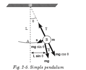
2.3.1 Simple Pendulum
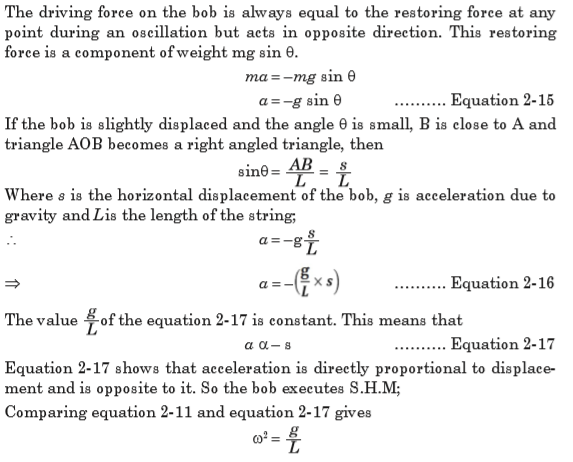
A simple pendulum consists of a small bob of mass m suspended from a fixed support through a light, inextensible string of length L as shown on Fig.2-5. This system can stay in equilibrium if the string is vertical. This is called the mean position or the equilibrium position. If the particle is pulled aside and released, it oscillates in a circular arc with the center at the point of suspension ‘O’.

Equation 2-18 represents the periodic time of a simple pendulum. Thus, the following are the factors affecting the periodic time of the simple pendulum;
• Length of string
• Angle from which pendulum is dropped
• Acceleration due to gravity
• Air resistance
EXAMPLE 2.4
A small piece of lead of mass 40 g is attached to the end of a light string of length 50 cm and it is allowed to hang freely. The lead is displaced to 0.5 cm above its rest position, and released.
(a) Calculate the period of the resulting motion, assuming it is simple harmonic.
(b) Calculate the maximum speed of the lead piece. (Take g = 9.81 ms–2)

EXAMPLE 2.5
What happens to the period of a simple pendulum if the pendulum’s length is doubled? What happens to the period if the mass of the suspended bob is doubled?


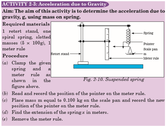
2.3.2 Mass suspended from a Coiled Spring
The extension of the spiral spring which obeys Hook’s law is directly proportional to the extending tension. A mass m is attached to the end of the spring which exerts a downward tension mg on it and stretches it by e as shown in Fig.2-7 below;


EXAMPLE 2.7
A light spiral spring is loaded with a mass of 50 g and it extends by 10 cm. Calculate the period of small vertical oscillations.


2.3.3Liquid in a U-tube
Consider a U-shaped tube filled with a liquid. If the liquid on one side of a U-tube is depressed by blowing gently down that side, the level of the liquid will oscillate for a short time about the respective positions O and C before finally coming to rest.


EXERCISE 2.2
1. A baby in a ‘baby bouncer’ is a real-life example of a mass-on-spring oscillator. The baby sits in a sling suspended from a stout rubber cord, and can bounce himself up and down if his feet are just in contact with the ground. Suppose a baby of mass 5.0 kg is suspended from a cord with spring constant 500 N m–1. Assume g = 10 N kg–1.
(a) Calculate the initial (equilibrium) extension of the cord.
(b) What is the value of angular velocity?
(c) The baby is pulled down a further distance, 0.10 m, and released. How long after his release does he pass through equilibrium position?
(d) What is the maximum speed of the baby?
(e) A simple pendulum has a period of 4.2 s. When it is shortened by 1.0 m the period is only 3.7 s.
(f) Calculate the acceleration due to gravity g suggested by the data.
2. A pendulum can only be modelled as a simple harmonic oscillator if the angle over which it oscillates is small. Why is this so?
3. What is the acceleration due to gravity in a region where a simple pendulum having a length 75.000 cm has a period of 1.7357 s? State the assumptions made.
4. A geologist uses a simple pendulum that has a length of 37.10 cm and a frequency of 0.8190 Hz at a particular location on the Earth. What is the acceleration due to gravity at this location?
5. Find the time taken for a particle moving in S.H.M. from
 Given that the period of oscillation is 12s.
 6. A spring is hanging from a support without any object attached to it and its length is 500 mm. An object of mass 250 g is attached to the end of the spring. The length of the spring is now 850 mm.
(a) What is the spring constant? The spring is pulled down 120 mm and then released from rest.
(b) Describe the motion of the object attached to the end of the spring.
(c) What is the displacement amplitude?
(d) What are the natural frequency of oscillation and period of motion? Another object of mass 250 g is attached to the end of the spring.
(e) Assuming the spring is in its new equilibrium position, what is the length of the spring?
(f) If the object is set vibrating, what is the ratio of the periods of oscillation for the two situations?
2.4 KINETIC AND POTENTIAL ENERGY OF AN OSCILLATING SYSTEM
Kinetic energy as the energy of a body in motion, change in velocity will also change it as shown on Fig.2-12. Velocity of an oscillating object at any point is given by equation 2-8;


When the particle is in oscillatory motion, work is done against the force trying to restore it. The energy stored to perform this work is called the potential energy.
Force on the particle;

Work done to restore the position of the particle after being displaced by x is given by;

Note that there is no work done when displacement is zero.

Substitute equation 2-32 into equation 2-33 to get;

2.5 ENERGY CHANGES AND ENERGY CONSERVATION IN AN OSCILLATING SYSTEM
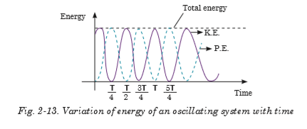
In an oscillation, there is a constant interchange between the kinetic and potential forms and if the system does no work against resistive force its total energy is constant. Fig.2-12 illustrates the variation of potential energy and kinetic energy with displacement x.

Substituting equation 2-3 for sinusoidal displacement into equation 2-34 and equation 2-35 gives;

The total energy of an oscillating system using equations 2.35 and 2.36 is given by;

The equation 2-38 of total energy indicates that this energy is constant and is independent of displacement x. Since the total energy of an oscillating particle is constant, it means that potential energy and kinetic energy vary in such a way that total energy is conserved.
Also substituting equation 2-35 and equation 2-36 into equation 2-37 will give an expression for the total energy of an oscillating system which is independent of time taken.

Fig.2-15 illustrates the variation of energy of an oscillating system with time.
EXAMPLE 2.8
A 0.500-kg cart connected to a light spring for which the force constant is 20.0 N/m oscillates on a horizontal, frictionless air track.
(a) Calculate the total energy of the system and the maximum speed of the cart if the amplitude of the motion is 3.00 cm.
(b) What is the velocity of the cart when the position is 2.00 cm?
(c) Compute the kinetic and potential energies of the system when the position is 2.00 cm.

2.6 SUPERPOSITION OF HARMONICS OF SAME FREQUENCY AND SAME DIRECTION


QUESTIONS
1.Give at least 2 examples of the applications of superposition in real life.
2. Derive the expression for the resultant displacement of two oscillations of the same frequency but acting in opposite directions.


(a) Find the period of its motion.
(b) Determine the maximum speed of the block.
(c) What is the maximum acceleration of the block?
(d) Express the position, speed, and acceleration as functions of time.
3. (a) A 10N weight extends a spring by 5cm. Another 10N weight is added, and the spring extends another 5cm. What is the spring constant of the spring?
(b) A pendulum oscillates with a frequency of 0.5 Hz. What is the length of the pendulum?
4. Christian Huygens (1629–1695), the greatest clockmaker in history, suggested that an international unit of length could be defined as the length of a simple pendulum having a period of exactly 1 s. How much shorter would our length unit be had his suggestion been followed?
5. A simple pendulum is suspended from the ceiling of a stationary elevator, and the period is determined. Describe the changes, if any, in the period when the elevator
(a) accelerates upward,
(b) accelerates downward, and (c) moves with constant velocity.
6. Imagine that a pendulum is hanging from the ceiling of a car. As the car coasts freely down a hill, is the equilibrium position of the pendulum vertical? Does the period of oscillation differ from that in a stationary car?
7. The diagram below shows a spring of stiffness K, attached to a mass m.

The mass is pulled by a distance a to the left and released. Show that the velocity of the mass can be modeled by;

Where x is the extension in the spring. What important assumption has to be made about the system?
8. What is the acceleration due to gravity in a region where a simple pendulum having a length 75.000 cm has a period of 1.7357 s?


Unit 3: FORCED OSCILLATIONS AND RESONANCE OF A SYSTEM
Unit 3: FORCED OSCILLATIONS AND RESONANCE OF A SYSTEM
Topic Area: OSCILLATIONS AND WAVES
Sub-Topic Area: Forced Oscillations and Resonance
Key unit competence: By the end of this unit I should be able to analyze the effects of forced oscillations on systems..
Unit Objectives:
By the end of this unit learners will be able to;
◊ Explain the concept of oscillating systems and relate it to the real life situations.
◊ Solve equations of different types of damped oscillations and derive the expression for displacement for each.
◊ explain resonance, state its conditions and explain its applications in everyday life.
3.0 INTRODUCTION
In the conventional classification of oscillations by their mode of excitation, oscillations are called forced if an oscillator is subjected to an external periodic influence whose effect on the system can be expressed by a separate term, a periodic function of the time, in the differential equation of motion. We are interested in the response of the system to the periodic external force. The behaviour of oscillatory systems under periodic external forces is one of the most important topics in the theory of oscillations. A noteworthy distinctive characteristic of forced oscillations is the phenomen of resonance, in which a small periodic disturbing force can produce an extraordinarily large response in the oscillator. Resonance is found everywhere in physics and thus, a basic understanding of this fundamental problem is required.
Opening questions
Comment on the following situations by giving clear reasons on each;
• A guitar string stops oscillating a few seconds after being plucked.
• To keep a child moving on a swing, you must keep pushing.
3.1 DAMPED OSCILLATIONS.
Unless maintained by some source of energy, the amplitude of vibration of any oscillatory motion becomes progressively smaller and the motion is said to be damped. The majority of the oscillatory systems that we encounter in everyday life suffer this sort of irreversible energy loss while they are in motion due to frictional or viscous heat generation generally. We therefore expect oscillations in such systems to eventually be damped.


In everyday life we experience some damped oscillations like:
(i) Damping due to the eddy current produced in the copper plate

(ii) Damping due to the viscosity of the liquid
3.2 EQUATION OF DAMPED OSCILLATIONS
Consider a body of mass m attached to one end of a horizontal spring, the other end of which is attached to a fixed point. The body slides back and forth along a straight line, which we take as x-axis of a system of Cartesian coordinates and is subjected to forces all acting in x-direction (they may be positive or negative). The motion equations for constant mass are based on Newton’s second law which can be expressed in terms of derivatives. In all derivations assume that m is the mass of an oscillating object, b is the damping constant and k is the spring constant.

Where b is the damping constant and the negative sign means that damping force always opposes the direction of motion of the mass.
The spring itself stores the energy that is used to restore the position of the mass once released after being slightly displaced. The restoring force of the spring is directly proportional to the displacement.

Where k is the spring constant and the negative sign means that the restoring force opposes the direction of motion of the mass. With this restoring force and the resisting force of the spring, the resultant force on the mass is;

Equation 3-5 is the differential equation of damping.
3.3 THE SOLUTION OF EQUATION OF DAMPING
To solve the differential equation 3-5 (of damping), we try a solution of the form;

Substituting in equation 3-5,

Equation 3-6 is called the auxiliary quadratic equation of the differential equation. Solving this equation for y gives;


3.4 TYPES OF DAMPED OSCILLATIONS.
3.4.1 Under damping oscillation
This is also called a lightly damped oscillation. For this oscillation, the displacement keeps varying with time and oscillations keep dying away slowly and slowly. The vibrating system keeps passing its original position and more time is taken by it to come to rest. This is the case where the value of equation 3-8 under the square root is negative;

This means that damping constant b is small relative to mass m and spring constant k. So the solution of equation 3-7 becomes;


Equation 3-11 represents the displacement of under damped oscillation. From this equation it can be interpreted that the value of x decreases as time increase, but due to the trigonometric function of sine and cosine in bracket makes its graph on Fig.3-3 cross the horizontal axis so many times. Examples of slightly damped oscillations include
Acoustics
(i) A percussion musical instrument (e.g. a drum) gives out a note whose intensity decreases with time. (slightly damped oscillations due to air resistance)
(ii) The paper cone of a loud speaker vibrates, but is heavily damped so as to lose energy (sound energy) to the surrounding air.
3.4.2 Over damped oscillation
Over damping is also called excessive or heavy damping. In this oscillation, displacement decreases with increase in time but the vibrating system takes a longer time to come to rest. This is the case where the value of equation 3-8 under the square root is positive.

One extremely important thing to notice is that in this case the roots are both negative. You can see this by looking at equation 3-7 where the square root is less than b. The term under the square root is positive by assumption, so the roots are real.

The solution for expression 3-5 is;

Equation 3-12 represents the displacement of over damped. This equation is fully exponential and keeps the value of x decreasing towards zero in a quite long time Fig.3-3.
3.4.3 Critically damped oscillation
This is also called natural damping and is when there is an intermediate dissipating force and the system reaches equilibrium position as fast as possible without oscillating. This rapid return to the equilibrium position ( 0 =x ) reduces the motion to rest in a shortest possible time. This is the case where the term (of equation 3-8) under the square root is 0 and the characteristic polynomial has repeated roots, i.e.

Now we use the roots to solve equation 3-5 in this case. We have only one exponential solution, so we need to multiply it by t to get the second solution.

Equation 3-14 represents the displacement of critically damped oscillation and shows that the displacement critically dies to zero in a short period of time as shown on Fig.3-3. It is possible to use the following values;

Where g is the damping coefficient, w0 is the natural frequency and t is the decay constant or the damping constant. Plotting equations 11, 12 and 14 on the same amplitude-time axes gives the general curve for damping oscillation as shown on Fig.3-3.
Examples of Critical damping
(a) Shock Absorber
It critically damps the suspension of the vehicle and so resists the setting up of vibrations which could make control difficult or cause damage. The viscous force exerted by the liquid contributes to this resistive force.

(b) Electrical Meters They are critically damped (i.e. dead-beat) oscillators so that the pointer moves quickly to the correct position without oscillation.

Analysis
• Calculate mean value for the time taken for the oscillator to come to rest for each radius of card.
• What is the uncertainty in the time taken to stop when the radius is 6 cm?
• Calculate this as a percentage of the mean value.
• What is the uncertainty in the time taken to stop when the radius is 8 cm?
• Calculate this as a percentage of the shortest time measurement at this radius.
• What is the uncertainty in the time taken to stop when the radius is 10 cm?
• Calculate this as a percentage of the longest time measurement at this radius.
• What type of error is responsible for the difference in the value of the time taken to come to rest?
• Calculate the area of the oscillator using
 . Write these values in the column provided.
 • What is the precision in the radius of card measurements?
• Calculate the percentage uncertainty in the 7.0 cm measurement.
• What will be the percentage uncertainty in the value of the area?
• Write down the upper and lower limits of the area.
• Plot a graph of radius of Oscillator (on the y axis) against time taken to come to rest.
• Describe the graph you have plotted.
• What does your graph suggest about the relationship between the two variables?
• Plot a graph of area of Oscillator (on the y axis) against time taken to come to rest.
• Describe the graph you have plotted.
• What does your graph suggest about the relationship between these two variables?
• Complete the final columns of the table by calculating the additional area each card adds to the oscillator and the time period as a percentage of the undamped time taken to come to rest.
• Do you notice any patterns or trends?
• Plot a graph of additional area (y axis) against percentage of undamped time taken to come to rest.
• How are these variables linked?
• Theory states that damping will not affect the time period of the SHM system. How could you prove this using the experimental set up described above?
3.5 NATURAL FREQUENCY OF A VIBRATION AND FORCED OSCILLATION.
The natural frequency of an object is the frequency of oscillation when released. e.g. a pendulum. A forced oscillation is where an object is subjected to a force that causes it to oscillate at a different frequency than its natural frequency. e.g. holding the pendulum bob in your hand and moving it along its path either more slowly or more rapidly than its natural swing. Examples on forced oscillation include:
A: Barton’s Pendulum
The oscillation of one pendulum by application of external periodic force causes the other pendulums to oscillate as well due to the transfer of energy through the suspension string. The pendulum having the same pendulum length and pendulum bob mass will have the same natural frequency as the original oscillating pendulum and will oscillate at maximum amplitude due to being driven to oscillate at its natural frequency causing resonance to occur.

B: Hacksaw blade oscillator
This is another example of resonance in a driven system. If the peiod of oscillation of the driver is changed by increasing the length of thread supporting the moving mass, the hacksaw blade will vibrate at a different rate. if we get the driving frequency right the slave will reach the resonant frequency and vibrate widely. Moving the masses on the blade will have a similar effect.

3.6 EQUATION OF FORCED OSCILLATION AND ITS SOLUTION
These are vibrations that are driven by an external force. A simple example of forced vibrations is a child’s swing: as you push it, the amplitude increases. A loudspeaker is also an example of forced oscillations; it is made to vibrate by the force of the magnet and the current on the coil fixed in the speaker cone.
In addition to the restoring and damping forces in the spring, one may have an external force which keeps the oscillation going. This is called a driving force. In many cases, this force will be sinusoidal in time with maximum force F0:

This equation differs from Equation 3-5 by the term on the right, which makes it in homogeneous.
The theory of linear differential equations tells us that any solution of the inhomogeneous equation added to any solution of the homogeneous equation will be the general solution.

We call the solution to the homogeneous equation the transient solution since for all values of b, the solution damps out to zero for times large relative to the damping time t.
We shall see that the solution of the inhomogeneous equation does not vanish and so we call it the steady state solution and denote it by
 It is this motion that we will now consider.
 The driving term forces the general solution to be oscillatory. In addition, there will likely be a phase difference between the driving term and the response. The derivations below gives the general solution in terms of the amplitude A and phase angle


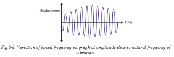
3.7 VARIATION OF FORCED FREQUENCY ON GRAPH AT AMPLITUDE CLOSE TO NATURAL FREQUENCY OF VIBRATION.
If an oscillating object is made to perform forced oscillations, closer is the frequency of force applied to the natural frequency, larger is the oscillation. However the amplitude rises and falls as the object will be assisted to oscillate for a short time and then the forces will oppose its motion for a short time. The graph shows the variation of the amplitude of the oscillations with time.
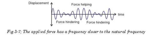
In figure 3.7, the applied force has a frequency closer to the natural
frequency. The amplitude of the oscillation has increased and there is time when the force helps and then hinders the oscillations.
The largest amplitude is produced when the frequency of the applied force is the same as the natural frequency of the oscillation. When the energy input from the applied force is equal to the energy loss from the damping, the amplitude stops increasing.
3.8 RESONANCE
Resonance occurs when an object capable of oscillating, has a force applied to it with a frequency equal to its natural frequency of oscillation.
Each time the force is applied it transfers energy to the oscillation and increases its amplitude. A very large amplitude occurs after a short time. e.g. pushing a child on a swing. You record your pushes to have the same frequency as the swing. The windows rattle when a truck goes by if the frequency of the sound made by the truck’s engine is the same as the natural frequency of the glass when it is tapped.
The oscillator resonates when the amplitude in equation 3-22 is maximum, and this occurs if;

In these equations, g is the damping coefficient and w0 is the natural frequency.
3.9 APPLICATIONS AND EXAMPLES OF RESONANCE IN EVERYDAY LIFE
The phenomenon of resonance depends upon the whole functional form of the driving force and occurs over an extended interval of time rather than at some particular instant. Below are examples of resonance in different applications;
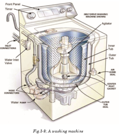
3.9.1 A washing machine
A washing machine may vibrate quite violently at particular speeds. In each case, resonance occurs when the frequency of a rotating part (motor, wheel, drum etc.) is equal to a natural frequency of vibration of the body of the machine. Resonance can build up vibrations of large amplitude.
3.9.2 Breaking the glass using voice
You must have heard the story of an opera singer who could shatter a glass by singing a note at its natural frequency. The singer sends out a signal of varying frequencies and amplitudes that makes the glass vibrate. At a certain frequency, the amplitude of these vibrations becomes maximum and the glasss fails to support it and breaks it. This scenarion is shown on Fig.3-10 below.

3.9.3 Breaking the bridge
The wind ,blowing in gusts, once caused a suspension bridge to sway with increasing amplitude until it reached a point where the structure was overstressed and the bridge collapsed. This is caused by the oscillations of the bridge that keep varying depending on the strength of the wind. At a certain level, the amplitude of oscillation becomes maximum and develops crack on it and suddenly breaks.

3.9.4 Musical instruments
Wind instruments such as flute, clarinet, trumpet etc. depend on the idea of resonance. Longitudinal pressure waves can be set up in the air inside the instrument. The column of air has its own natural frequencies at which it can vibrate. When we blow, we use the mouthpiece to start some vibrations. Those which happen to match exactly the natural frequencies of the instrument are picked out and magnified.

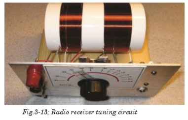
3.9.5 Tuning circuit
The another example of useful resonance is the tuning circuit on a radio set. Radio waves of all frequencies strike the aerial and only the one which is required must be picked out. This is done by having a capacitance inductance combination which resonates to the frequency of the required wave. The capacitance is variable; by altering its value other frequencies can be obtained.
3.9.6 Microwave Ovens
Microwave ovens use resonance. The frequency of microwaves almost equals the natural frequency of vibration of a water molecule. This makes the water molecules in food to resonate. This means they take in energy from the microwaves and so they get hotter. This heat conducts and cooks the food.

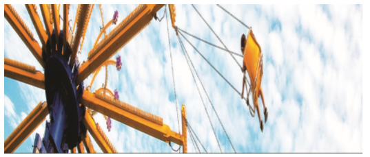
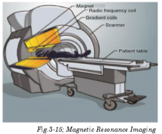
3.9.7 Magnetic Resonance Imaging (MRI)
The picture showing the insides of the body was produced using magnetic resonance imaging (MRI). Our bodies contain a lot of hydrogen, mostly in water. The proton in a hydrogen spins. A spinning charged particle has a magnetic field, so the protons act like small magnets. These are normally aligned in random directions. Placing a patient in a strong magnetic field keeps these mini magnets align almost in line. Their field axis just rotates like a spinning top. This is called processing.


3.10 EFFECT OF RESONANCE ON A SYSTEM
◊ Vibrations at resonance can cause bursting of the blood vessel.
◊ In a car crash a passenger may be injured because their chest is thrown against the seat belt.
◊ The vibration of kinetic energy from the wave resonates through the rock face and causes cracks.
◊ It is also used in a guitar and other musical instruments to give loud notes.
◊ Microphones and diaphragm in the telephone resonate due to radio waves hitting them.
◊ Hearing occurs when eardrum resonates to sound waves hitting it.
◊ Soldiers do not march in time across bridges to avoid resonance and large amplitude vibrations. Failure to do so caused the loss of over two hundred French infantry men in 1850.
◊ If the keys on a piano are pushed down gently enough it is possible to avoid playing any notes. With the keys held down, if any loud noise happens in the room (e,g. Somebody shouting), then some of the notes held down will start to sound.
◊ An opera singer claims to be able to break a wine glass by loudly singing a note of a particular frequency.
EXAMPLES
1. Solve the following initial value problem and determine the natural frequency, amplitude and phase angle of the solution.


2. Solve the following initial value problem. For each problem, determine whether the system is under, over, or critically damped:


Unit 4: PROPAGATION OF MECHANICAL WAVES
Unit 4: PROPAGATION OF MECHANICAL WAVES
Topic Area: OSCILLATIONS AND WAVES
Sub-Topic Area: Waves
Key unit competence: By the end of the unit I should be able to evaluate the propagation of mechanical waves.
Unit Objectives:
By the end of this unit learners will be able to;
◊ Explain the terms, concept and characteristics of waves properly.
◊ Explain the properties of waves.
◊ Explain the behavior of waves in vibrating strings and applications of waves properly.

4.0 INTRODUCTION
When we think of the word “wave”, we usually visualize someone moving his hand back and forth to say ‘hello’ or maybe we think of a tall curling wall of water moving in from the ocean to crash on the beach.
In physics, a wave is a disturbance that occurs in a material medium and in such process, energy is transferred from one place to another. When studying waves, it’s important to remember that they transfer energy, not matter.
There are lots of waves all around us in everyday life. Sound is a type of wave that moves through matter and then vibrates our eardrums and we hear. Light is a special kind of wave that is made up of photons that helps us to see. You can drop a rock into a pond and see wave formation in the water. We even use waves (microwaves) to cook our food really fast. Application of this concept is extensively used in telecommunication and music.
Classroom demonstration
(a) Arrange the students in the form of a circle with their right shoulders pointing towards the centre.
(b) Ask one student to raise arms and then lower them. Then the next student raises arms and lowers them, and so on around the circle. It should be like the “wave” in a football stadium.
(c) After the students have the hang of it, ask them what the disturbance in the wave was.
(d) Ask them if the disturbance travels up and down or horizontally around the circle.
(e) Let one student gently push the back of the next student and then the pushed student should gently push the next student and so on, which will make a wave travel around the ring.
(f) Ask students: What is the disturbance? Is the disturbance travelling up and down or around the ring? Which way does the wave travel? Because this disturbance travels in the same direction as the wave, it is a longitudinal wave.
4.1 THE CONCEPT OF WAVES
Waves can be defined as a disturbance in a medium that transfers energy from one place to another, although the medium itself does not travel.
The term wave is often intuitively understood as referring to a transport of spatial disturbances that are generally not accompanied by a motion of the medium occupying this space as a whole. In a wave, the energy of a vibration is moving away from the source in the form of a disturbance within the surrounding medium.
Other properties, however, although usually described in terms of origin, may be generalized to all waves. For such reasons, wave theory represents a particular branch of physics that is concerned with the properties of wave processes independently of their physical origin.
4.2 TERMS USED AND CHARACTERISTICS OF WAVES
All waves are characterized by the following terms;
The Time period (T) of the wave is the time it takes for one wavelength of the wave to pass a point in space or the time for one cycle to occur. It is also defined as the time taken between two successive wave crests or trough. It is measured in seconds (s).
The frequency (f) is the number of wavelengths that pass a point in space per second. In another words, it can be defined as the number of complete oscillations or vibrations per second. Its SI unit is hertz (Hz). Mathematically;

The wavelength
 is the horizontal distance in space between two nearest points that are oscillating in phase (in step) or the spatial distance over which the wave makes one complete oscillation. Its SI unit is metre (m).
 The wave speed
 is the speed at which the wave advances. Its SI unit is m/s.
That is, wave speed = wavelength × frequency.
This is the relationship between wavelength, frequency and velocity.
Amplitude is defined as the maximum distance measured from equilibrium position (mean position). The amplitude is always taken as positive and is measured in metres.
Phase difference (phase angle) is the angular difference between two points on the wave or between two waves. Consider, two points O and P on the wave as shown in Fig. 4-4.
Phase difference is a whole number and is calculated using simple proportions;

The wave number, also called the propagation number k, is the spatial frequency of a wave, either in cycles per unit distance or radians per unit distance. It can be envisaged as the number of waves that exist over a specified distance (analogous to frequency being the number of cycles or radians per unit time). Its unit is per metre (m–1). Mathematically;

The Intensity (I) of a wave or the power radiated by a source are proportional to the square of the amplitude (x).

Wavefront is a line or surface in the path of the wave motion on which the disturbance at every point have the same phase. This can also be defined as the surface which touches all the wavelets from the secondary sources of waves. Consider the Huygens construction principle for the new wavefront.

4.3 TYPES OF WAVES
There are two types of waves called mechanical waves and electromagnetic waves. These waves are classified based on conditions necessary for the wave to propagate.
4.3.1 Mechanical waves
These waves are produced by the disturbance in a material medium and they are transferred by particles of the medium. These waves include waves in strings, water waves and sound waves. Mechanical waves are classified as progressive or standing waves.
4.3.1.1 Progressive waves
A progressive wave is also called a travelling wave which consists of a disturbance moving from one point to another. As a result, energy is transferred between points. Progressive mechanical waves can be categorised according to the direction of the effect of the disturbance relative to the direction of travel. Progressive waves are classified as longitudinal and transverse waves.
4.3.1.1.1 Longitudinal waves
When a wave propagates through some medium and the local displacements of the medium that constitute the disturbance are in the direction of travel of the disturbance, then the wave is longitudinal.
An example of a longitudinal wave is the pulse that can be sent along a stretched slinky by shaking one end of the slinky along its length. The pulse moves along the line of the slinky and ultimately makes the other end move. Notice that in this case, the individual coils of the slinky vibrate back and forth about some equilibrium position, but there is no net movement of the slinky itself.

4.3.1.1.2 Transverse waves
These are waves in which the direction of disturbance is perpendicular to the direction of travel of the wave. The particles do not move along with the wave; they simply oscillate up and down about their individual equilibrium positions as the wave passes by.

4.3.1.1.3 Equation of a progressive wave
An equation can performed to represent displacement yof a vibrating particle in a medium in which a wave passes. Suppose a wave moves from left to right and that a particle at the origin moves with displacement given by equation.


EXAMPLE 1
A travelling wave is described by the equation y(x, t) = 0.003 cos (20x + 200t) where y and x are measured in meters and t in seconds. What is the direction in which the wave is travelling? Calculate the following physical quantities:
(a) angular wave number
(b) wavelength
(c) angular frequency
(d) frequency
(e) time period
(f) wave speed
(g) amplitude
particle velocity when x = 0.3 m and t = 0.02 s
(i) particle acceleration when x = 0.3 m and t = 0.02 s

4.3.1.2 Principle of superposition
The displacement at any time due to any number of waves meeting simultaneously at a point in a medium is the vector sum of the individual displacements of each one of the waves at that point at the same time.
This means that when two waves travel in a medium, their combined effect at any point can be determined using this principle. Consider two waves of displacements y1 and y2 passing through the same medium. The resultant displacement after superposition is:

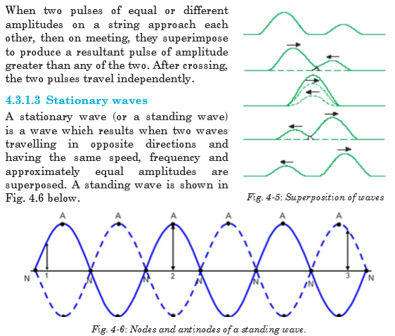
Here, A denotes the antinodes and N denotes the nodes.
Mathematical treatment of standing waves
Consider the displacement y1 = a sin (wt – F) of a progressive sinusoidal wave at time t and at a distance x from the origin and moving to right.
Consider also the displacement y2 of an identical wave travelling in opposite direction given by;

If these waves are superposed, the resultant displacement y is given by;

The only variable part of equation 4.18 is sin wt. This means that the amplitude of the resultant displacement is given by equation

Position of antinodes
Antinodes are points of maximum displacements. So, antinodes are obtained when the value of Equation 4.19 is maximum. This occurs when;

EXAMPLE 2

4.3.1.4 Examples of mechanical waves
Mechanical waves, being progressive and stationary, are seen in different forms as described in this section.
Sound waves

Water waves
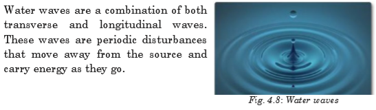
Ocean waves
These waves are longitudinal waves that are observed moving through the bulk of liquids, such as our oceans. Ocean waves are powerful forces that erode and shape of the world’s coastlines. Most of them are created by the wind. Winds that blow over the top of the ocean, create friction between the air and water molecules, resulting in a frictional drag as waves on the surface of the ocean.

Earthquake waves
Earthquakes occur when elastic energy is accumulated slowly within the Earth’s crust (as a result of plate motions) and then released suddenly along fractures in the crust called faults. Earthquake waves are also called seismic waves and actually travel as both transverse and longitudinal waves.
The P waves (Primary waves or compressional waves) in an earthquake are examples of longitudinal waves. The P waves travel with the fastest velocity and are the first to arrive.

The S waves (Secondary waves or shear waves) in an earthquake are examples of transverse waves. S waves propagate with a velocity slower than P waves, arriving several seconds later.

Body Waves
Body waves are of two types: compressional or primary (P) waves which are longitudinal in nature and shear or secondary (S) waves which are transverse in nature. P- and S- waves are called ‘body waves’ because they can travel through the interior of a body, such as the Earth’s inner layers, from the focus of an earthquake to distant points on the surface. The Earth’s molten core are only travelled by compressional waves.

4.3.2 Electromagnetic waves
These waves consist of disturbances in the form of varying electric and magnetic fields. No material medium is necessary for their movement and they travel more easily in vacuum than in matter.

Examples of electromagnetic waves are: Radio waves, Microwaves, Infrared radiation, Visible light, Ultraviolet light, X-rays and Gamma rays. These waves vary according to their wavelengths.

4.4 PROPERTIES OF WAVES
This section introduces the properties of waves and wave motion to describe the behavior of waves in detail.
4.4.1 Reflection
This is the property of waves to bounce back from the surface on which they hit. Huygens principle can also be applied to reflection. Consider a parallel beam of light incident on the reflecting surface such that its direction of travel makes an angle i with the normal to the surface.

Consider that side A of an associated wavefront AB has just reached the surface. In the time that light from side B of the wavefront travels to B′, a secondary wavelet of radius equal to BB′ will be generated by A. Because of the reflecting surface, this wavelet is a semicircle above the surface.
The new wavefront generated by reflection will be the tangent to this

We conclude by saying that all laws of reflection are obeyed. So, any wavefront can reflect.
4.4.2 Refraction
Consider a parallel beam of waves (for example light waves) incident on a refracting surface between two media such that its direction of travel makes angle q1 with the normal to the refracting surface.
Consider side A of the wavefront AB has reached the surface before B. If the ray from the other side B of the beam consequently travels to C at time t,


At the same time, wavelets from A travel distance AD in medium 2. Here, a refracted wavefront CD is formed by many wavelets in the beam. Fig.4-16 above illustrates this description.

Equation 4-32 confirms Snell’s law meaning that waves behave like normal light during reflection.
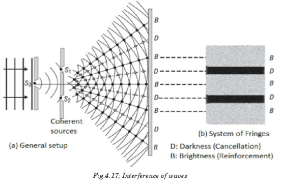
4.4.3 Interference
In the region where wave trains from coherent sources (sources of the same frequency) cross, superposition occurs giving reinforcements of waves at some points which is called constructive interference and cancellation at others which is called destructive interference. The resulting effect is called interference pattern or the system of fringes.
4.4.4 Diffraction
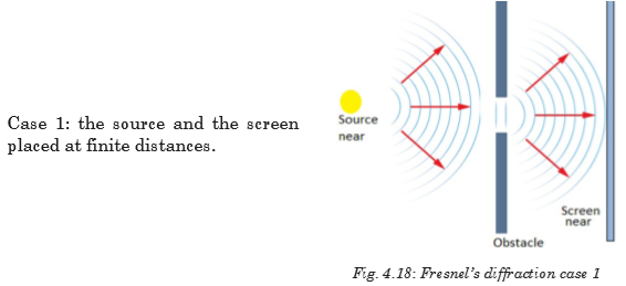
This is a phenomenon in which waves from one source meet an obstacle and spread around it. Diffraction is normally observed when these waves pass through narrow slits. There are two types of diffraction and these are; Fresnel’s diffraction and Fraunhofer diffraction.
4.4.4.1 Fresnel’s diffraction
This is a type of diffraction in which either the source of waves or screen on which diffraction is observed or both are at finite distances from the obstacle that cause diffraction. Below are different cases to explain this diffraction.
Case 3: the screen is placed at infinite distance from obstacle and the source is near.

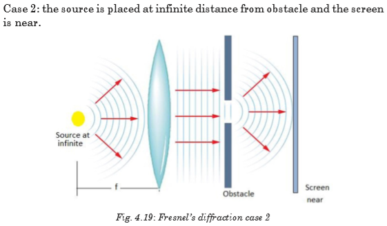
4.4.4.2 Fraunhofer Diffraction
This is a type of diffraction in which the source of waves and the screen on which diffraction is observed are effectively at infinite distances from the obstacle. This phenomenon is practically complicated but theoretically understood. To obtain waves to or from infinite source in laboratory, biconvex lenses are used.

4.5 YOUNG’S DOUBLE SLIT EXPERIMENT
In this experiment, a source S of monochromatic waves is used to illuminate two narrow and parallel slits S1 and S2 that are apparent sources of light. The arrangement is shown in Fig.4.22.

From the above experiment, a narrow slit S diffracts light falling on it and so illuminates S1 and S2. Diffraction also takes place at S1 and S2 and interference takes place in the region where light from S1 overlaps the light from S2. Light from S1 and S2 is from a monochromatic source, hence S1 and S2 act as coherent sources (they are also monochromatics).
4.6 WAVE ON A VIBRATING STRING
When a string is fixed at one end and the other end is moved up and down, a transverse wave is formed. The simplest mode of vibration is the one in which both ends are nodes. Let us use l as the wavelength, l as the length of the string, c as the speed of the wave and f as the frequency of the wave.

The figure above shows the simplest mode of vibration which is the first harmonic (fundamental mode) and its frequency f1 is called the fundamental frequency. Higher order frequencies are called overtones. The second harmonic is the first overtone and has the mode shown by Fig.4-24.


EXAMPLE 4
A wire of length 400 mm and mass 1.2 × 10⁻³ kg is under a tension of 120 N. What is
(a) the fundamental frequency of vibration?
(b) the frequency of the third harmonic?


4.7 APPLICATIONS OF WAVES
1. They are used in radar, broadcasting and radio communication.
2. They are used in MRI in hospitals.
3. They are also used in radio communication which forms an integral part of wireless communication.


Across
1. How fast something is moving or how much distance is covered in a certain amount of time.
2. The time it takes for a wave to repeat itself
4. The lowest point of a wave beneath the line of origin
9. Waves that require a medium
10. The highest point of a wave above the line of origin
11. Particles of light
12. A push or a pull
13. The tendency of an object at rest to remain at rest or in motion until acted upon
Down
2. Waves that do not require a medium
5. The bouncing back of a wave when it meets the surface or boundary
6. The matter through which a wave travels
7. Distance in a given direction
8. The vertical distance between the line of origin and the crest of a wave


Materials to choose from:
3 white screens, 3 biconvex lenses
, 3 biconcave lenses
The question:
Explain how you can perform Fresnel’s diffraction and Fraunhofer diffraction in the laboratory.
Hypothesis:
Write a hypothesis about how diffraction is obtained in the lab.
Procedure
1. Decide which materials you will need (from the list) to test the hypothesis.
2. Plan your investigation.
a. Which arrangements best gives the idea of diffraction?
b. Which adjustments do you care to take care of ?
3. Write a procedure and show it to your teacher. Do not proceed any further until it is approved.
4. Carry out your investigation.
Collecting Data
Make sure you have recorded at least the following information:
◊ the hypothesis
◊ your procedure
Analyzing and Interpreting
Share and compare your results with your classmates. Which idea is important to be used and achieve the proper arrangement of apparatus to achieve your objective?
Forming Conclusions
Make a brief report of your project with neat diagrams. In this project what is needed is the concept not the analysis of the fringes formed.


Unit 5: COMPLEX ELECTRICAL CIRCUIT
Unit 5: COMPLEX ELECTRICAL CIRCUIT
Topic Area: ELECTRICITY
Sub-Topic Area: Current Electricity
Key topic competence: By the end of the unit I should be able to construct and to analyze a complex electrical circuit.
Unit Objectives:
By the end of this unit, learners should be able to:
◊ analyze complex electrical circuits well.
◊ use Kirchhoff’s laws in circuit analysis accurately
◊ analyze simple potentiometer circuits clearly.

5.0 INTRODUCTION
A complex circuit configuration is one that contains components that are connected either in parallel or in series with each other. If a circuit can be reduced to a single resistor, it is a series or parallel circuit. If not, it is a complex circuit. If the circuit is complex and is mixed with series and parallel networks of resistors and supplies, we may want to look if it is feasible to reduce these to a single power supply and a single resistor which would make them either a series or a parallel simple circuit.
Most electronic devices we use at home have built-in complex circuits to perform different tasks. Also the concept of this unit is helpful in other subjects like electrons and conductors (in Chemistry), volume adjustment circuits in radios.
Opening questions


5.1 KIRCHHOFF’S LAWS
Next to Ohm’s Law in the fundamental rules which govern the behaviour of electric circuits are Kirchhoff’s Circuit Laws. Gustav Kirchhoff in 1845 formulated two circuit laws, one of which essentially establishes the conservation of charge and the other establishes the conservation of potential.

Sign conventions
• The potential change across a resistor is – IR if the loop is traversed along the chosen direction of current (potential drops across a resistor).
• The potential change across a resistor is + IR if the loop is traversed opposite the chosen direction of current.
•If an emf source is traversed in the direction of the emf, the change in potential is positive.
• If an emf source is traversed in the opposite direction of the emf, the change in potential is negative.
5.1.1 Kirchhoff’s Current Law
Kirchhoff’s first law, known as Kirchhoff’s Current Law (KCL) or Kirchhoff’s Junction Rule, essentially expresses the conservation of charge, which can be thought of as the conservation of matter. This implies that charge cannot
appear from anything at any point in a circuit, neither can it disappear into oblivion at any point.
Kirchhoff’s Current Law states that “the algebraic sum of the currents flowing at a node or junction in an electric circuit is zero”.
This means that currents are added with respect to their directions. Let us consider the junction shown on Fig. 5.3 below.

From the figure;

Note that both forms are completely mathematically consistent.
EXAMPLE 5.1
In the circuit of Fig. 5.4, the magnitudes of the currents are as follows:


Notes: Any calculated value of current which works out to be negative simply indicates that in practice, the current is actually flowing in a direction opposite to that assigned in the schematic diagram of the circuit.
5.1.2 Kirchhoff’s Voltage Law
Kirchhoff’s second circuit law, known as Kirchhoff’s Voltage Law (KVL) or Kirchhoff’s Loop Rule, essentially formulates the conservation of energy in the form of electric potential around a circuit in which current is flowing. This means that no net voltage can be created or destroyed around the loop of a closed circuit.
Kirchhoff’s Voltage Law states that “the algebraic sum of the potentials around a closed electric circuit is zero.”
Consider an electrical network shown in Fig. 5.5 below.

EXAMPLE 5.2
In the circuit of Fig.5.5, the magnitudes of the potentials are as follows:

5.2 DESIGN OF COMPLEX AND SIMPLE ELECTRIC CIRCUITS
An electric circuit is a collection of electrical components connected by conductors. A simple electric circuit consists of a supply with either series or parallel network of resistors.

This circuit contains neither simple series nor simple parallel connections. It contains elements of both. Because the circuit is a combination of both series and parallel, we cannot apply the rules for voltage, current and resistance “across the table” to begin its analysis. This is shown below;


5.3 RESISTORS AND ELECTROMOTIVE FORCES IN SERIES AND PARALLEL COMPLEX CIRCUITS
This section examines how Kirchhoff’s voltage and current laws are applied to the analysis of complex circuits. In the analysis of such series-parallel circuits, we often simplify the given circuit to enable us to clearly see how the rules and laws of circuit analysis apply. We might need to redraw circuits whenever the solution of a problem is not immediately apparent. Resistors are said to be in series if they are arranged side by side in a such way that the total potential difference is shared by all resistors and the current flowing through them is the same. This arrangement is shown below:
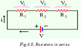
A parallel circuit is a circuit in which the resistors are arranged with their heads connected together, and their tails connected together. The current in a parallel circuit breaks up, with some flowing along each parallel branch and re-combining when the branches meet again. The voltage across each resistor in parallel is the same.
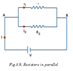
The same idea of series and parallel resistors is applied in series and parallel cells. For series e.m.fs the total e.m.f is equivalent to the sum of individual e.m.fs with respect to the direction of currents they generate.

When these cells are connected in parallel, the total e.m.f e equivalent to the e.m.f of only one cell.
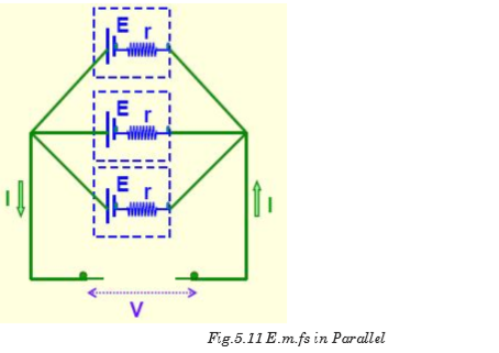
To solve the resistor circuits using Kirchhoff’s rules,
1. Define the various currents
• This can be done by either defining branch (segment) currents for each element in the circuit, or defining loop currents for each loop in the circuit.
2. If using branch currents, use Kirchhoff’s Junction Rule to look for interdependent currents. This allows for reducing the number of variables being solved for.
3. Use Loop Rule to define voltage equations for each loop, using previously defined currents.
4. Solve set of simultaneous equations using algebraic manipulation.
EXAMPLE 5.3
Using Kirchhoff’s rules, calculate the currents I1, I2 and I3 in the three branches of the circuit in Fig.5.12.


Ammeter
An ammeter is a device which is used to measure electric current flowing through a branch of a circuit. Electric current is measured in amperes (A). Smaller currents are measured by milliammeters (mA) and microammeters (mA). Ammeters are of various types–moving coil ammeter, moving magnet ammeter, moving iron ammeter, hot wire ammeter, etc. Nowadays, digital
ammeters are used to measure current accurately which use ADC (analog to digital converter). An ammeter is connected in series with the circuit through which current is flowing.

Voltmeter
A voltmeter is a device which is used to measure electric potential difference between two points in an electrical circuit. Electric p.d. is measured in along a calibrated scale in proportion to circuit voltage. Digital voltmeters are now frequently used to give a display of voltage using ADC. A voltmeter is always connected in parallel to the component across which p.d. is to be measured.
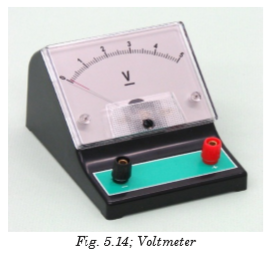
5.4 SIMPLE POTENTIOMETER CIRCUITS
A simple potentiometer is a device used for taking a number of electrical measurements. It is a piece of resistance wire, usually a meter long, fixed between two points A and B with a cell of output voltage, V, connected between the two ends.
The potential difference to be measured is put into a circuit together with an opposing variable p.d. from the voltage divider. The voltage divider is then adjusted until its p.d., VAC equals the p.d. being measured. Fig. 5.15 illustrates this.

The sliding contact in the above diagram is moved until the galvanometer indicates zero. This position is referred to as the balance point. The current in the lower part of the circuit is zero because the p.d., VAC equals the p.d. E provided by the cell under test. The protective resistor serves only to prevent the galvanometer from the damage.
Electromotive force of the wire is always proportional to the length of the wire. So, the approximate value of E is determined as follows:

EXAMPLE 5.4
A potentiometer is set up as shown in the Fig.5.16 and the balance point for the unknown e.m.f., E is found at 84 cm from the left hand end of the meter wire. If the driver cell has e.m.f. of 1.5V and negligible internal resistance, find the value of unknown e.m.f.


EXAMPLE 5.5
What value of resistance is needed in series with a driver cell of negligible internal resistance and approximately 3V e.m.f. to arrange that
 of the
  slide wire is required to balance a p.d. of 1.5V?

5.4.1 Comparison of e.m.f.s
A potentiometer may sometimes be used to compare e.m.f’s of a cell with that of a standard cell. Consider the circuit of Fig. 5.18 below.


So if the standard e.m.f. E0 is known, lengths l0 and l are known, then E1 can be calculated.
EXAMPLE 5.6
In Fig.5.19, AB is a uniform wire of length 1.2 m and resistance 8 W. A driver cell of e.m.f. 3V and internal resistance 1W is driving a current Ip as shown. Calculate the e.m.f. of the cell Ex if the balance length is 66.5 cm.


5.6.2 Measurement of internal resistance of a cell
The circuit is arranged as shown in Fig. 5.20 with the cell, whose internal
resistance r is to be found, is connected in parallel with a resistor with resistance R and a switch. The driver cell as usual is in the upper loop of the circuit.

The balance point l is found with the switch open. Since at balance point, no current is flowing through G; E is then measured. The switch is then closed and the new balance point l1 is found. Balance length l1 is proportional to output voltage V (across the resistor R); i.e.

EXAMPLE 5.7
In the circuit of Fig. 5.21 below, AB is a uniform wire of length 1m and resistance 4.0 W. C1 is an accumulator of e.m.f. 2 V a negligible internal resistance. C2 is a cell of e.m.f. 1.5 V.

(a) Find the balance length AD when the switch is open.
(b) If the balance length is 75.0 cm when the switch is closed, find the internal resistance of C2.


(b) When the switch is closed, the internal resistance of the cell can be calculated from equation 5.15.
5.5 MEASUREMENT OF CURRENT BY POTENTIOMETER
Consider the circuit of Fig. 5.22 shown below. Current through a resistor can be calculated at the balance point.
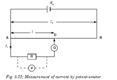
The potential difference, p.d. across R can be found by finding the balance point on the potentiometer such that if the balance point is at C then VAC balances the p.d. across R. If R is known, then the current can be found.


EXERCISE 5.1
1. A potentiometer is set up as shown in Fig. 5.25. Given that the balancing point for the unknown e.m.f. E is found to be 74.5 cm from the left hand end of the meter wire (1m). If the driver cell has an e.m.f. of 1.5 V and negligible internal resistance. Find the value unknown e.m.f.

2. A certain cell is connected to a potentiometer and a balance point is obtained at 84 cm along the meter wire. When its terminals are connected to a 5W resistor, the balance point changes to 70 cm. Calculate the balance when a 5W resistor is now replaced by a 4W resistor.

5.6 ADVANTAGES AND DISADVANTAGES OF POTENTIOMETER
Wear: Most potentiometers last only a few thousand rotations before the materials wear out. Although it means years of service in some applications, it takes special designs to stand up to daily, demanding use. It means they can’t be used for machine sensing where rapid cycling would wear them out in a matter of minutes.
Noise: The action of the wiper moving across the element creates a noise called “fader scratch.” In new pots, this noise is inaudible, but it can get worse with age. Dust and wear increase the bumpiness of the action and make the noise noticeable. Small cracks can appear in the element, and these make noise as the wiper moves over them.
In addition to these mechanically caused noises, carbon elements, in particular, are prone to producing electrical noise. This noise is heard as a soft, steady hiss that can degrade sound recordings. The resistive materials have improved over the years, so newer pots are quieter.
Inertia: The friction between the potentiometer’s wiper and resistive element creates a drag or inertia that the pot must overcome before it turns. Although this drag is not large, it prevents the pot from being used as a rotary sensor in more sensitive applications.
Limited Power: Out of necessity, most potentiometers can dissipate only a few watts of power. To handle more power, they have to be larger and hence expensive. Engineers work around this problem by putting the potentiometer in low-power parts of circuits. They control small currents, which, in turn, control transistors and other components with greater power ratings.

1. What are Kirchhoff’s rules for understanding a circuit?
2. Explain why Kirchhoff’s junction rule must be true if the Law of Conservation of Charge (that no charge may be created or destroyed) is true.
3. Explain why Kirchhoff’s loop rule must be true if the Law of Conservation of Energy is true.
4. Find the branch currents of the circuit shown below.

5. Solve the circuit for currents I1, I2, and I3, using Kirchhoff’s rules.

6. Find the current flowing in the resistor R3 of 40W.


Kirchhoff’s laws
There are two Kirchhoff’s laws: Kirchhoff’s Current Law states that “the algebraic sum of the currents flowing at a node or junction in an electric circuit is zero.”
Kirchhoff’s Voltage Law states that “the algebraic sum of the potentials around a closed electric circuit is zero.”
To solve the resistor circuits using Kirchhoff’s rules
1. Define the various currents
• Can either define branch (segment) currents for each element in the circuit
• Or can define loop currents for each loop in the circuit
2. If using branch currents, use Kirchhoff’s Junction Rule to look for interdependent currents. This allows for reducing the number of variables being solved for.
3. Use Loop Rule to define voltage equations for each loop, using previously defined currents.
4. Solve set of simultaneous equations using algebraic manipulation. A simple potentiometer is a device used for taking a number of electrical measurements. It is a piece of resistance wire, usually a metre long, fixed between two points A and B with a cell of output voltage, V,
connected between the two ends.
Potentiometer can be used to
(i) compare e.m.f.’s of two primary cells.
(ii) measure internal resistance of a cell.
Unit 6: FOSSIL AND NON-FOSSIL FUEL AND POWER PRODUCTION
Unit 6: FOSSIL AND NON-FOSSIL FUEL AND POWER PRODUCTION
Topic Area: ENERGY, POWER AND CLIMATE CHANGE
Key unit competence: By the end of this chapter, I should be able to evaluate fossil and non-fossil fuel for power production.
Unit Objectives:
By the end of this unit learners will be able to;
◊ explain the concept of fossil and no-fossil fuels and their use in power production properly.
◊ explain the differences between fossil and no-fossil fuels properly.
◊ explain Nuclear fuel and nuclear fission and their use in energy production and associated dangers properly.
◊ explain the environmental problems of fossil fuels and suggest their solution clearly.
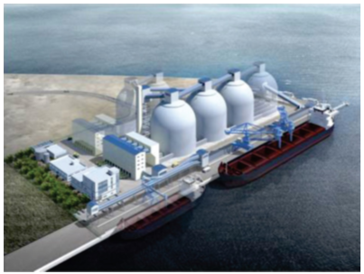
6.0 INTRODUCTION
Fossil fuel is a source of conventional or non-renewable energy. There are many examples of fossil fuels which we use in our daily lives. In fact, most of the energy that we consume comes from fossil fuels. Coal, petroleum and natural gas are called fossil fuels. Millions of years ago, during the carboniferous age, due to the change in atmospheric conditions and other changes, the forests were destroyed and they were fossilized. With the action of bacteria and other microorganisms on the surface of the earth, these trees and other vegetation were decayed and disintegrated. Years after these trees were available in solid, liquid and gaseous state. The solid form is coal. It is the most widely used form of fossil fuel for domestic purposes.


6.1 FOSSIL FUELS AND NON-FOSSIL FUELS
6.1.1 Fossil Fuels
Fossil fuels are hydrocarbons, primarily coal, fuel oil or natural gas, formed from the remains of dead plants and animals. In common dialogue, the term ‘fossil fuel’ also includes hydrocarbon-containing natural resources that are not derived from animal or plant sources.

Coal, oil and natural gas are called ‘fossil fuels’ because they have been formed from the fossilized remains of prehistoric plants and animals. Fossil fuels are non-renewable energy source since they take millions of years to form. They ultimately get their energy from the sun.
Types of Fossil Fuels
Coal
Coal is a hard, black coloured rock-like substance formed when dead plants were subjected to extreme heat and pressure for millions of years. It is made up of carbon, hydrogen, oxygen, nitrogen and varying amounts of sulphur. There are two ways to mine coal: surface mining and underground mining.
Natural Gas
Natural gas is formed from the remains of tiny sea animals and plants that died millions of years ago. The gas then became trapped in layers of rocklike water in a wet sponge. Raw natural gas is a mixture of different gases. Its main ingredient is methane. The strange smell of natural gas (like rotten eggs) comes from a chemical added by the companies. It is called mercaptan. This is added to detect the gas leakage.
Oil (Petroleum)
Oil is formed from the remains of animals and plants that died millions of years ago. The organic material was then broken down into hydrogen and carbon atoms and a sponge-like rock was formed, full of oil.
Oil cannot be used as it is when it is drawn from the ground. Oil refineries clean and separate the oil into various fuels and byproducts. The most important of these is gasoline.
Fossil fuels are used to generate electrical energy in a series of energy transformations as shown in Fig.6.2.

6.1.2 Non-fossil fuels
Non-fossil fuels are alternative sources of energy or renewable sources of energy that do not rely on burning up limited supplies of coal, oil or natural gas. Examples of these fuels include: nuclear energy, wind or water generated energy and solar power. These tend to be renewable energy sources, or means of generating power that can be utilized indefinitely.
Non-fossil fuels are considered to be extremely important for power creation. This is because they are usually renewable energy sources that could be tapped for hundreds of years and not run out. In addition, energy production using nonfossil-based fuels usually generates much less pollution than fossil-based energy sources.
6.2 STORAGE AND TRANSPORTATION OF DIFFERENT TYPES OF FOSSIL FUELS
6.2.1 Coal
Types of coal
• Peat
• Lignite
• Semi bituminous
• Bituminous
• Anthracite
Means of transporting coal
• Transportation by rail
• Transportation by ropeways
• Transportation by sea or river
• Road transport
• Transport by pipeline
Coal storage
Storage of coal is undesirable because it costs more as there is:
• Risk of spontaneous combustion,
• Weathering,
• Possibility of loss and deterioration during storage,
• Interest on capital cost of coal lying dormant,
• Cost of protecting the stored coal from deterioration.
Types of coal storage
1. Dead storage:
This storage supplies the coal to places where there is a shortage of coal in plant due to failure of normal supply of coal. This is a long-term storage and comprises 10% of annual consumption, so, it requires protection against weathering and spontaneous combustion.
2. Living storage:
It supplies coal to plant for day-to-day usage. The capacity of live storage is less than that of dead storage. It is usually stored in vertical cylindrical bunkers or coal basins or silos, e.g. coal is transferred to boiler grate. Bunkers are normally diamond-shaped cross-section storage areas made up of steel or reinforced concrete.
Purpose of dead coal storage of coal
• To prevent shutdown of power plant in case of failure of normal supplies of coal due to coal strike, failure of the transport system, etc.
• To permit choice of purchase allowing management to take advantage of seasonal market conditions.
Means of coal storage
1. Storage in coal heaps
It is required to:
• Keep coal at low temperature (>70 oC).
• Prevention of air circulation from bottom of coal piles.
• Proper drainage of rainy water to prevent weathering–drainage should not be rapid to prevent washing of coal.
Hence, ground used for stocking should be dry and levelled for proper drainage. It should have concrete floor to prevent flow of air from bottom. Coal is piled up to a height of about 10 to 12 m in layers of 15 to 30 cm.
In dead storage, coal pile is sealed by asphalt, fine coal dust, bituminous or other coating materials.
2. Underwater storage
Possibility of slow oxidation and spontaneous combustion can be completely eliminated by storing coal under water.

Site selection for coal dead storage
• The storage should be free from standing water
• If well drainage is not available, artificial drainage should be provided.
• It should be free from all foreign materials like wood, paper rags, waste oil or materials having low ignition temperature.
• Handling cost should be minimum.
• Pile should build up in successive layers and be compact.
• Pile should be dressed to prevent entry of rainy water.
• Alternative drying and wetting should be avoided.
• Stoker size coal should be oil treated to prevent absorption of water and oxygen.
• Side of pile should not be steep.
• Air may circulate freely through pile for proper ventilation to keep temperatures low.
• Hot surfaces or boiler blow down or hot water or steam pipe and tanks should be kept far from coal storage
• Hot bright days should be avoided.
• There should be provision for temperature measurement at different points.
• Conical piling should be avoided.
• Fire fighting equipment should be easily available.
Coal Transfer
Equipment used in coal transfer are:
A: Belt conveyor
It can transfer large quantities of coal over large distance economically. It has low initial cost and ensures low power consumption.

Advantages:
• Economical, low power consumption
• Large capacity
• Rate of coal transfer rapidly change
• Low maintenance cost
Disadvantages
• Not suitable for shorter distance and inclination > 200.
• Not suitable for dust particles and slurry.
B: Flight conveyor
It is used when coal is discharged at different points in bins situated below the conveyor. All parts are made of steel and iron, so it can handle hot materials. It is totally enclosed, so dust of coal can get transferred. It can transfer coal at high inclination

Advantages
• It requires small head room.
• Speed and material transfer rate can easily change.
• It can handle hot materials also.
Disadvantages
• High wear and tear, so, it has short life.
• High maintenance required.
• Speed is limited up to 300 m/min due to abrasive action of material.
• High power consumption per unit of material transfer.
C: Screw conveyor
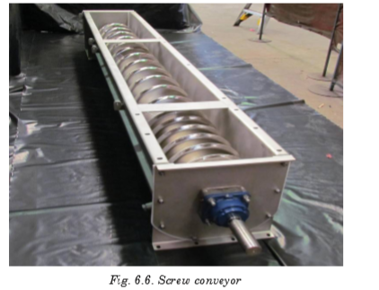
• It is used for shorter distance.
• It is totally enclosed from atmosphere.
• Coal dust can also be transferred easily.
• It is generally used in metering of coal.
• Driving mechanism is attached at the end of the shaft.
• Diameter: 15 cm to 50 cm.
• Speed: 70 rpm to 120 rpm.
• Capacity: 125 tones/h (max)
Advantage
• Cheap initial cost.
• Simple and compact.
• Dust tight.
• It can transfer coal at high inclination also.
• Most suitable for short distance.
Disadvantages
• High power consumption.
• Length is limited up to 30 m.
• High maintenance due to high wear and tear.
D: Bucket elevator
It is used for vertical lifts. Buckets are fixed on chain which moves on two wheels or sprockets. Buckets are loaded at bottom and discharged at top.

E: Grab bucket elevator
• It is used for lifting as well as transfer material.
• It can be used with crane or tower.
• Initial cost is high but operating cost is less.
• It is used when another arrangement is not possible.
• Bucket capacity: 2 to 3 m3
• Distance: 60 m
• Capacity: 100 tonnes/h.
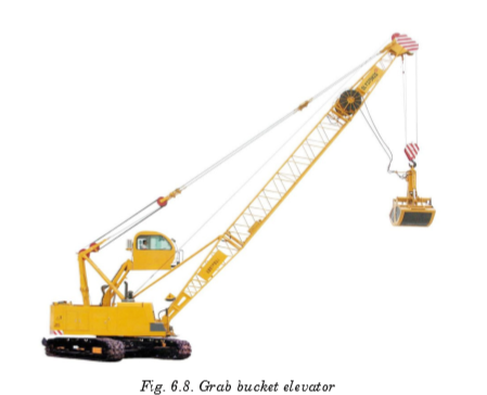
6.2.2 Transporting Natural Gas and Crude Oil
Transporting natural gas and crude oil thousands of miles through pipelines is the safest method of transportation. The transportation system for natural gas consists of a complex network of pipelines, designed to transport natural gas from its origin to the areas of high natural gas demand quickly and efficiently. In general, pipelines can be classified in three categories depending on the purpose:
Gathering pipelines
These are smaller interconnected pipelines forming complex networks with the purpose of bringing crude oil or natural gas from several nearby wells to a treatment plant or processing facility. In this group, pipelines are usually short — a couple of hundred metres — and with small diameters. Also subsea pipelines for collecting product from deep water production platforms are considered gathering systems.
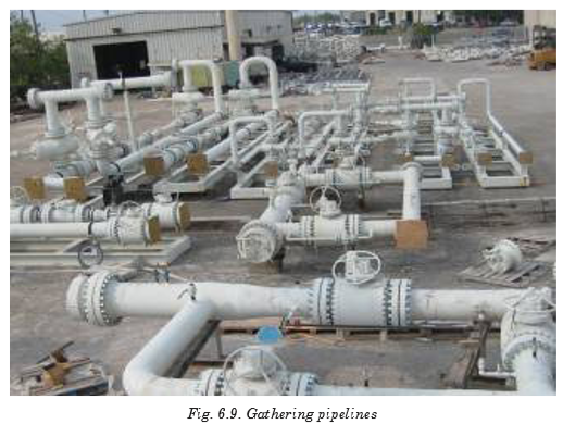
Transportation pipelines
These are long pipes with large diameters, moving products (oil, gas, refined products) between cities, countries and even continents. These transportation networks include several compressor stations in gas lines or pump stations for crude and multi-products pipelines.
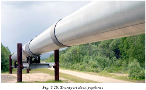
Distribution pipelines
These are composed of several interconnected pipelines with small diameters, used to take the products to the final consumer. Feeder lines to distribute gas to homes and business downstream, and pipelines at terminals for distributing products to tanks and storage facilities, are included in this group.

6.3 ADVANTAGES AND DISADVANTAGES OF FOSSIL FUELS


6.4 ENERGY PRODUCTION USING FOSSIL FUELS
A fossil-fuel power station is a power station which burns fossil fuels, such as coal, natural gas or petroleum to produce electricity. Central station fossilfuel power plants are designed on a large scale for continuous operation.

There are two main cycles in a power plant; the steam cycle and the gas turbine cycle. The steam cycle relies on the Rankine cycle in which high pressure and high temperature steam raised in a boiler is expanded through a steam turbine that drives an electric generator. The generator then transforms mechanical energy into electrical energy which is distributed for local use.
The steam gives up its heat of condensation to a heat sink, such as water from a river or a lake and the condensate can then be pumped back into the boiler to repeat the cycle. The heat taken up by the cooling water in the condenser is dissipated mostly through cooling towers into the atmosphere.
6.5 NUCLEAR FUEL AND NUCLEAR FISSION
Nuclear fuel is any material that can be consumed to derive nuclear energy. The nuclear fuel can be made to undergo nuclear fission chain reactions in a nuclear reactor. The most common nuclear fuels are 235U (uranium 235) and 239Pu (plutonium 239). Not all nuclear fuels are used in fission chain reactions.
Nuclear fission is a process, by which a heavy nucleus splits into two or more simpler pieces. This process releases a lot of energy.
When a neutron strikes an atom of uranium, the uranium nucleus splits into two lighter atoms and releases heat simultaneously. Fission of heavy elements is an exothermic reaction which can release large amounts of energy both as electromagnetic radiation and as kinetic energy of the fragments.

A chain reaction refers to a process in which neutrons released in fission produce an additional fission in at least one further nucleus. This nucleus in turn produces neutrons, and the process continues. If the process is controlled it is used for nuclear power or if uncontrolled it is used for nuclear weapons. Fig.6.13 illustrates a chain reaction of uranium 235.
The equation of reaction is:

6.6 CONTROLLED FISSION (POWER PRODUCTION)
Of the three neutrons, liberated during a fission reaction, only one triggers a new reaction and the others are simply captured. The system is in equilibrium. One fission reaction leads to one new fission reaction, which leads to one more, and so on. This is known as controlled fission.

In a nuclear power station, the uranium is first formed into pellets and then into long rods. The uranium rods are kept cool by submerging them in water. When they are removed from the water, a nuclear reaction takes place causing heat production. The amount of heat required is controlled by raising and lowering the rods. If more heat is required, the rods are raised further out of the water and if less heat is needed, they are lowered further into it.
6.7 UNCONTROLLED FISSION (NUCLEAR WEAPONS)
A fission reaction which is allowed to proceed without any moderation (by removal of neutrons) is called an uncontrolled fission reaction. Here more and more neutrons are given out and cause more fission reactions, thus, releasing large amounts of energy. An uncontrolled fission reaction is used for nuclear bombs.
Using the energy released from the nuclear fission of uranium-235, an explosive device can be made by simply positioning two masses of U-235 so that they can be forced together quickly enough to form a critical mass and result in a rapid, uncontrolled fission chain reaction.
This is not an easy task to accomplish. First, you must obtain enough uranium which is highly enriched to over 90% U-235, since natural uranium is only 0.7% U-235.This enrichment is an exceptionally difficult task, a fact that has helped control the proliferation of nuclear weapons. Once the required mass is obtained, it must be kept in two or more pieces until the moment of detonation. Then the pieces must be forced together quickly and in such a geometry that the generation time for fission is extremely short. This leads to an almost instantaneous build up of the chain reaction, creating a powerful explosion before the pieces can fly apart. Two hemispheres which are explosively forced into contact, can produce a bomb, such as the one detonated at Hiroshima in 1945.

6.8 IMPACTS OF NUCLEAR WEAPONS
There are five immediate destructive effects from a nuclear explosion:
1. The initial radiation, mainly gamma rays;
2. An electromagnetic pulse, which in a high altitude explosion can knock out electrical equipment over a very large area;
3. A thermal pulse, which consists of bright light (even many miles away) and intense heat equal to that at the centre of the sun);
4. A blast wave that can flatten buildings; and
5. Radioactive fallout, mainly in dirt and debris that is sucked up into the mushroom cloud and then falls to earth.
There are three long-term effects of a nuclear explosion:
1. Delayed radioactive fallout, which gradually fall over months and even years to the ground, ofen in rain;
2. A change in the climate (possibly by lowering of the earth’s temperature over the whole hemisphere which could ruin agricultural crops and cause widespread famine);
3. A partial destruction of the ozone layer, which protects the earth from the sun’s ultraviolent rays. If ozone layer is depleted, unprotected Caucasians would get an incapacitating sunburn within 10 minutes, and people would suffer a type of snow blindness from the rays which, if repeated, would lead to permanent blindness. Many animals would suffer the same fate.
6.9 ENERGY TRANSFORMATIONS IN A NUCLEAR POWER STATION
In a nuclear power plant, Nuclear Steam Supply System (NSSS) consists of a nuclear reactor and all of the components necessary to produce high pressure steam, which will be used to turn the turbine for the electrical generator.

The nuclear reactor contains some radioactive isotopes like uranium which undergo fission reaction when bombarded with some neutrons and a large amount of heat energy is evolved. This heat energy converts water into steam, which is piped to the turbine. In the turbine, the steam passes through the blades, which spins the electrical generator, resulting in a flow of electricity. After leaving the turbine, the steam is converted (condensed) back into water in the condenser. The water is then pumped back to the nuclear reactor to be reheated and converted back into steam.
6.10 PROBLEMS ASSOCIATED WITH THE PRODUCTION OF NUCLEAR POWER
• The problem of radioactive waste is still unsolved. The waste from nuclear energy is extremely dangerous and it has to be carefully looked after for several thousand years (10,000 years according to United States Environmental Protection Agency standards).
• High risks: Despite a generally high security standard, accidents can still happen. It is technically impossible to build a plant with 100% security. A small probability of failure will always last. The consequences of an accident would be absolutely devastating both for human beings and the nature. The more nuclear power plants (and nuclear waste storage shelters) are built, the higher is the probability of a disastrous failure somewhere in the world.
• Nuclear power plants as well as nuclear waste could be preferred targets for terrorist attacks. Such a terrorist act would have catastrophic effects for the whole world.
• During the operation of nuclear power plants, radioactive waste is produced, which, in turn, can be used for the production of nuclear weapons. In addition, the same is used to design nuclear power plants can to a certain extent be used to build nuclear weapons (nuclear proliferation).
• The energy source for nuclear energy is Uranium. Uranium is a scarce resource; its supply is estimated to last only for the next 30 to 60 years depending on the actual demand.
• The timeframe needed for formalities, planning and building of a new nuclear power generation plant, is in the range of 20 to 30 years in the western democracies. In other words, it is an illusion to build new nuclear power plants in a short time.
6.11 ENVIRONMENTAL PROBLEMS OF FOSSIL FUELS
Climate Change/Global Warming and Greenhouse Effect
The earth’s atmosphere allows a lot of sunlight to reach the earth’s surface but reflects much of that light back into space. Some gases trap more sunlight, therefore, less light is reflected back into space. These gases are called Greenhouse Gases, because the effect is like being in a plant glasshouse, or in a car with the windows wound up. The result is a gradual increase in the earth’s temperature or Global Warming. The major greenhouse gases are carbon dioxide, methane, nitrous oxide and chlorofluorocarbons (CFCs).
The main man made causes are thought to be carbon dioxide and methane from factory, power station and car emissions, the waste products of respiration, the mining of fossil fuels and the breakdown of plant matter in swamps. The long-term effects may include melting of glaciers and a rise in sea level and a global change in climate and type of vegetation.
‘Hole’ in the Ozone Layer
Ozone is a gas in the earth’s upper atmosphere whose chemical formula is O3. Ozone acts to block out much of the sun’s ultraviolet radiation which causes skin cancer and contributes to the fluctuations of global climatic conditions that affect the environment. Above Antarctica, there is a thinner layer of ozone caused by the destruction of ozone gas by emissions of chlorofluorocarbons and hydrochlorofluorocarbons which are propellants in pressure-pack spray cans and refrigerants in refrigerators and airconditioning units.
Acid Rain
When gases, such as sulphur dioxide and nitrogen oxides react with water in the atmosphere to form sulphuric acid and nitric acid, they form an acidic ‘rain’ which can destroy vegetation. Some of these gases are from natural sources, such as lightning, decomposing plants and volcanoes. However, much of these gases are the result of emissions from cars, power stations, smelters and factories.
Air Pollution
Air pollution is the release of excessive amounts of harmful gases (e.g. methane, carbon dioxide, sulphur dioxide, nitrogen oxides) as well as particles (e.g. dust of tyre, rubber, lead from car exhausts) into the atmosphere. To reduce emissions, the Australian government has legislated that all new cars should use unleaded petrol and have catalytic converters fitted to the exhausts.
Water Pollution
1. Sewage is the household waste water. Many detergents contain phosphates which act as plant fertilisers. When these phosphates and the sewerage reach rivers, they help water plants to grow in abundance, reducing the dissolved oxygen in the river water. The result is death of aquatic animals due to suffocation by the algal blooms. This harmful effect is called eutrophication. Eutrophication is also caused by excessive use of fertilizers in agricultural fields and subsequent surface run-off.
2. Biodegradable detergents are more environment-friendly because they are readily broken down to harmless substances by decomposing bacteria.
3. Suspended solids in water, such as silt reduce the amount of light that reaches the depths of the water in lakes and rivers. This reduces the ability of aquatic plants to photosynthesise and reduce the plant and animal life. Turbidity is the measure of ‘cloudiness’ or the depth to which light can reach in water.
Introduced Species
They are species of plants or animals that have migrated or been brought to Australia. Many fit into the natural ecosystems and are kept in control by natural predators and parasites. However, some become pests as they are well-adapted to that environment, readily obtain nutrients and lack of natural predators or parasites. Examples include rabbits, foxes, carp and prickly pear cactus plant.
Biological Control
It is an environment-friendly method to control these pests by the introduction of species-specific, living organisms to control their numbers. Successful examples include the myxoma virus and the calici virus for rabbits, and the cactoblastis moth feeding on the prickly pear. Unsuccessful examples include the introduction of the cane toad to reduce the numbers of natural cane beetles.
Soil Salinity
Soil salinity has increased greatly since the widespread logging of trees by farmers. Deep tree roots normally draw water from the underground water table. However, when logging of trees occurs, the water table rises close to the surface bringing with it, salt from rocks. This makes the soil salty so that vegetation cannot grow effectively. The result is loss of vegetation and erosion.
Population Explosion
It is the rapid increase in population in developing countries causing famine, and also in developed countries causing more demand for energy and with that, it increases pollution and destruction of the environment.


6.12 SAFETY ISSUES AND RISKS ASSOCIATED WITH NUCLEAR POWER
6.12.1 Nuclear Meltdown
A nuclear meltdown is an informal term for a severe nuclear reactor accident that results in core damage from overheating.

A nuclear meltdown occurs when a nuclear power plant system or component fails so the reactor core becomes overheat and melts. Usually, this occurs due to the lack of coolant that decreases the temperature of the reactor. The commonly used coolant is water but sometimes a liquid metal, which is circulated past the reactor core to absorb the heat, is also used. In another case, a sudden power surge that exceeds the coolant’s cooling capabilities causes an extreme increase in temperature which leads to a meltdown. A meltdown releases the core’s highly radioactive and toxic elements into the atmosphere and environment.
The causes of a meltdown occur due to:
A: A loss of pressure control
The loss of pressure control of the confined coolant may be caused by the failure of the pump or having resistance or blockage within the pipes. This causes the coolant to cease flow or insufficient flow rate to the reactor; thus, the heat transfer efficiency decreases.
B: A loss of coolant
A physical loss of coolant, due to leakage or insufficient provision, causes a deficit of coolant to decrease the heat of the reactor. A physical loss of coolant can be caused by leakages. In some cases, the loss of pressure control and the loss of coolant are similar because of the systematic failure of the coolant system.
C: An uncontrolled power excursion
A sudden power surge in the reactor is a sudden increase in reactor reactivity. It is caused by an uncontrolled power excursion due to the failure of the moderator or the control that slows down the neutron during chain reaction. A sudden power surge will create a high and abrupt increase of the reactor’s temperature, and will continue to increase due to system failure. Hence, the uncontrollable increase of the reactor’s temperature will ultimately lead to a meltdown.
6.12.2 Nuclear (Radioactive) Wastes
Nuclear wastes are radioactive materials that are produced after the nuclear reaction. Nuclear reactors produce high-level radioactive (having high levels of radioactivity per mass or volume) and low-level (having low levels of radioactivity) wastes. The wastes must be isolated from human contact for a very long time in order to prevent radiation.

The ‘high-level wastes’ will be converted to a rock-like form and placed in a natural habitat of rocks, deep underground. The ‘low-level wastes’, on the other hand, will be buried in shallow depths (typically 20 feet) in soil.
A number of incidents have occurred when radioactive material was disposed improperly, where the shielding during transport was defective, or when the waste was simply abandoned or even stolen from a waste store.
The principal risks associated with nuclear power arise from health effects of radiation, which can be caused due to contact with nuclear wastes. This radiation consists of sub-atomic particles travelling at or near the velocity of light (186,000 miles per second). They can penetrate deep inside the human body where they can damage biological cells and thereby initiate a cancer. If they strike sex cells, they can cause genetic diseases in progeny.


1. Why should solar energy be harnessed to take care of our electric power needs?
2. How do we confirm that the ‘greenhouse effect’ is real?
3. How does acid rain destroy forests and fish?
4. Is it possible to eliminate the air pollution from coal burning?
5. Radioactivity can harm us by radiating from sources outside our bodies, by being taken in with food or water or by being inhaled into our lungs. But we consider only one of these pathways. Why is it so?
6. Cancers from radiation may take up to 50 years to develop, and genetic effects may not show up for a hundred years or more. How, then, can we say that there will be essentially no health effects from the Three Mile Island accident?
7. Air pollution may kill people now, but radiation induces genetic effects that will damage future generations. How can we justify our enjoying the benefits of nuclear energy while future generations bear the suffering from it?
8. Can the genetic effects of low-level radiation destroy the human race?
9. Isn’t the artificial radioactivity created by the nuclear industry, more dangerous than the natural radiation which has always been present?
10. Can radiation exposure to parents cause children to be born with two heads or other such deformities?
11. Can a reactor explode like a nuclear bomb?
12. If reactors are so safe, why don’t home owners’ insurance policies cover reactor accidents? Does this mean that insurance companies have no confidence in them?
13. How is radioactive waste disposed off?
14. How long will the radioactive waste be hazardous?
15. How will we get rid of reactors when their useful life is over?

Fossil fuels are hydrocarbons, primarily coal, fuel oil or natural gas, formed from the remains of dead plants and animals.
Types of Fossil Fuels
• Coal
• Natural Gas
• Oil (Petroleum)
Types of coal storage
• Dead storage
• Living storage
Means of coal storage
• Storage in coal heaps
• Underwater storage
Energy production using fossil fuels
A fossil-fuel power station is a power station which burns fossil fuel, such as coal, natural gas or petroleum to produce electricity.
Nuclear fuel and nuclear fission Nuclear fuel is any material that can be consumed to derive nuclear energy.
Controlled fission (power production)
When a fission reaction leads to a new fission reaction, which leads to another one and so on, it is called controlled fission. The amount of heat required is controlled by raising and lowering the rods in the reactor.
Uncontrolled fission (nuclear weapons)
A fission reaction whereby the reaction is allowed to proceed without any moderation (by removal of neutrons) is called an uncontrolled fission reaction. An uncontrolled fission reaction is used for nuclear bombs.
Problems associated with the production of nuclear power
• problem of radioactive waste.
• high risks.
• targets for terrorist attacks.
• nuclear weapons.
• uranium is a scarce resource.
• illusion to build new nuclear power plants.
Environmental problems of fossil fuels
Climate Change / Global Warming and Greenhouse Effect
The earth’s atmosphere allows a lot of sunlight to reach the earth’s surface, but reflects much of that light back into space.
The result is a gradual increase in the earth’s temperature or Global Warming.
‘Hole’ in the Ozone Layer
Ozone acts to block out much of the sun’s ultraviolet radiation which causes skin cancer and contributes to the fluctuations of global climatic conditions that affect the environment.
Acid Rain
When gases, such as sulphur dioxide and nitrogen oxides react with water in the atmosphere to form sulphuric acid and nitric acid, they form an acidic ‘rain’ which can destroy vegetation.
Air Pollution
Air pollution is the release into the atmosphere of excessive amounts of harmful gases as well as particles.
Other environmental problems of fossil fuels include:
• Biological Control
• Biological Magnification
• Introduced Species
• Soil Salinity
• Population Explosion
Unit 7: ELECTRIC FIELD POTENTIAL AND GRAVITATIONAL POTENTIAL
Unit 7: ELECTRIC FIELD POTENTIAL AND GRAVITATIONAL POTENTIAL
Topic Area: Motion in fields
Sub-Topic Area: Electric field Potential and Energy
Key unit competence: By the end of this unit, I should be able to analyze electric field potential and gravitational potential.
Unit Objectives:
By the end of this unit, learners will be able to;
◊ list the properties of an electric and gravitational fields and the variation of potentials properly.
◊ explain the working mechanism of a cathode ray tube, TV tubes and computer monitors properly.
◊ explain the everyday applications of electric and magnetic fields.

7.0 INTRODUCTION
Electricity might be leading technological advancement, but its study began with nature. Electrical storms are a very dramatic example of natural phenomena involving electricity. Other examples are found in animals. Some use electricity as a tool for survival – as a weapon (by electric eels) or to sense live food (by platypus and sharks). Animals routinely use electricity to control their bodies. The story of Frankenstein’s monster, brought to life during an electrical storm, was inspired by early experiments where the legs of a dead frog were made to twitch by sending electrical current through them. Today we use electrical technology not just to support our everyday lives in a myriad of ways, but also to diagnose muscle and nerve activity inside the body, and to assist faulty signaling in the body.
7.1 ELECTRIC FIELD AND ELECTRIC POTENTIAL DUE TO A POINT CHARGE


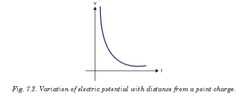
7.2 ELECTRIC POTENTIAL ENERGY AND POTENTIAL DIFFERENCE
To apply conservation of energy, we first need to define electric potential energy. As we saw in level four, potential energy can be defined only for conservative forces. The work done by a conservative force in moving an object between any two positions is independent of the path taken. The electrostatic force between any two charges is conservative because of its dependence on position just like gravitational force. Hence, we define the potential energy for electrostatic force, assuming potential energy at infinity to be zero as


The potential difference between these two points can be calculated as the difference between their respective electrical potentials as:

7.3 EQUIPOTENTIAL LINES AND SURFACES
The electric potential can be represented by drawing equipotential lines or equipotential surfaces. An equipotential surface is the one on which all points are at the same potential. The potential difference between any two points on the surface is zero, so no work is required to move a charge from one point on the surface to the other. An equipotential surface must be perpendicular to the electric field at any point. If this was not so—that is, if there was a component of
 parallel to the surface—it would
 require work to move the charge along the surface against this component of
; and this would contradict the idea that it is an equipotential surface. The fact that the electric field lines and equipotential surfaces are mutually perpendicular, helps us locate the equipotentials when the electric field lines are known. In a normal two-dimensional drawing, we show equipotential lines, which are the intersections of equipotential surfaces with the plane of the electric field line.
In Fig. 7.5, a few of the equipotential lines are drawn (dashed green lines) for the electric field (red lines) between two parallel plates maintained at a potential difference of 20 V. The negative plate is arbitrarily chosen to be zero volts and the potential of each equipotential line is indicated.
Note that
points towards lower values of V. 7.4 POTENTIAL DUE TO ELECTRIC DIPOLE
The equipotential lines for the case of two equal but oppositely charged particles are shown in Fig. 7.6 as green dashed lines.

Unlike electric field lines, which start and end on electric charges, equipotential lines and surfaces are always continuous curves, and continue beyond the borders indicated in Figs. 7.5 and 7.6.
7.5 CONSERVATION OF ELECTRICAL ENERGY
Energy is conserved in the movement of a charged particle through an electric field, as it is in every other physical situation. Electric charge cannot be created or destroyed (though positive and negative charges can neutralise each other).
Given a stationary test charge at a certain location, an applied electric field will cause the charge to move to one end or the other, depending on the charge.
Positive test charges will move in the direction of the field; negative charges will move in the opposite direction.
At the instant at which the field is applied, the motionless test charge has zero kinetic energy, and its electric potential energy is at the maximum. Now the charge accelerates, and its kinetic energy (due to motion) increases as its potential energy decreases. The sum of energies is always constant.
The formula illustrating conservation of energy can be written in many ways, but all expressions are based on the simple premise of equating the initial and final sums of kinetic (Ekin) and potential (Epot) energy.


7.6 CATHODE RAY TUBE
The CRT is a vacuum tube in which a beam of electrons is accelerated and deflected under the influence of electric or magnetic fields. The electron beam is produced by an assembly called an electron gun located in the neck of the tube. These electrons, if left undisturbed, travel in a straightline path until they strike the front of the CRT, the “screen’’, which is coated with a material that emits visible light when bombarded with electrons.
The operation of a CRT depends on thermionic emission, discovered by Thomas Edison (1847–1931). Consider a voltage applied to two small electrodes inside an evacuated glass “tube” as shown in Fig. 7.7: the cathode is negative, and the anode is positive. If the cathode is heated (usually by an electric current) so that it becomes hot and glowing, it is found that negative charges leave the cathode and flow to the positive anode. These negative charges are now called electrons, but originally they were called cathode rays because they seemed to come from the cathode.
Fig. 7.7 is a simplified sketch of a CRT which is contained in an evacuated glass tube. A beam of electrons, emitted by the heated cathode, is accelerated by the high-voltage anode and passes through a small hole in that anode. The inside of the tube face on the right (the screen) is coated with a fluorescent material that glows at the spot where the electron hits. Voltage applied across the horizontal and vertical deflection plates can be varied to deflect the electron beam to different spots on the screen. The instruments used in the laboratory to display, measure and analyze the waveforms of different circuits is known as cathode ray oscilloscope.

7.7 TV AND COMPUTER MONITORS
In TV and computer monitors, the CRT electron beam sweeps over the screen in the manner shown in Fig. 7.8 by carefully synchronizing voltages applied to the deflection plates. This is called scanning.
During each horizontal sweep of the electron beam, the grid receives a signal voltage that limits the flow of electrons at each instant during the sweep; the more negative the grid voltage is, the more electrons are repelled and fewer pass through, producing a less bright spot on the screen. Thus, the varying grid voltage is responsible for the brightness of each spot on the screen. At the end of each horizontal sweep of the electron beam, the horizontal deflection voltage changes dramatically to bring the beam back to the opposite side of the screen, and the vertical voltage changes slightly so the beam begins a new horizontal sweep slightly below the previous one. The difference in brightness of the spots on the screen forms the “picture”.
Color screens have red, green, and blue phosphors which glow when struck by the electron beam. The various brightnesses of adjacent red, green and blue phosphors (so close together we don’t distinguish them) produce almost any colour. With 30 new frames or pictures every second (25 in countries with 50-Hz line voltage), a “moving picture” is displayed on the TV screen. The commercial movies present 24 frames per second as the film runs.

7.8 TRAJECTORY OF A CHARGE MOVING IN A CATHODE RAY TUBE
If electrons enter an electric field in a CRT acting at right angles to their direction of motion, they are deflected from their original path. In Fig. 7.9, a p.d is applied between the plates P and Q of length l, creates an electric field of intensity E. Consider an electron of charge e, mass m and velocity v entering the field.


EXAMPLE 7.1
A beam of electrons moving with velocity 1 × 10⁷ m/s enters mid-way between two horizontal parallel plates P and Q in a direction parallel to the plates as shown on Fig.7-10. P and Q are 5 cm long and 2 cm apart, and have a p.dV applied between them.


1. Fig. 7.11 shows two metal plates 2.0 cm long placed 5 mm apart. A fluorescent screen is placed 20.0 cm from one of the plates. An electron of kinetic energy 3.2 × 10⁻⁶ J is incident mid-way between the plates. Calculate the voltage applied across the plates to deflect the electron 2.1 cm on the screen. Assume that the electron moves through vacuum.

2. In the diagram of Fig. 7.12, P and Q are parallel metal plates each of length l = 4 cm. A p.d of 12V is applied between P and Q. The space between P and Q is virtual. A beam of electrons of speed 1.0 × 10⁶ m/s is directed mid-way between P and Q at right angles to the electric field between P and Q. Show that the electron beam emerges from the space between P and Q at an angle of 64.6° to the initial direction of the beam.

7.9 ELECTRODYNAMICS
This is the study of phenomena associated with charged bodies in motion and varying electric and magnetic fields. Since a moving charge produces a magnetic field, electrodynamics is concerned with effects such as magnetism, electromagnetic radiation and electromagnetic induction, including some practical applications as the electric generator and the electric motor.
This area of electrodynamics, often known as classical electrodynamics, was first systematically explained by the physicist James Clarke Maxwell. Maxwell’s equations, a set of differential equations, describe the phenomena of this area with great generality. A more recent development is quantum electrodynamics, which was formulated to explain the interaction of electromagnetic radiation with matter, to which the laws of the quantum theory apply.
When the velocities of the charged particles under consideration become comparable with the speed of light, corrections involving the theory of relativity must be made; this branch of the theory is called relativistic electrodynamics. It is applied to phenomena involved with particle accelerators and with electron tubes that are subject to high voltages and carry heavy currents.
7.10 GRAVITATIONAL FIELD AND GRAVITATIONAL POTENTIAL


Let Me be the mass of the earth;
The force of attraction between the earth and the mass m is:

Where r is the distance of the mass from the center of the earth. The work done by gravitational force in moving a mass through a distance dr towards the earth is:

Since we are considering a unit mass, m = 1 kg

So the total work done in moving a unit mass from infinity to a point located at distance R from the center of the earth is obtained by integration:

The negative sign indicates that potential at infinity is higher than potential at a point closer to the centre of the earth.
7.11 ESCAPE VELOCITY FOR A PLANET
If the rocket is fired from the surface of the earth with velocity v such that
it just escapes from the influence of the earth’s gravitational pull, then this velocity is called escape velocity.
Work done W.d. on a mass m at the surface of the earth of mass Me and radius Re is:

From work energy theorem, this work done equals the kinetic energy of the rocket as it escapes from the earth’s surface.

When the object of mass m is on the surface of the earth, the gravitational force equals the weight of the object;

This time the distance r equals the radius of the earth Re. This gives;

Notes
With an initial velocity about 11 km/s, a rocket will completely escape from the gravitational attraction of the earth and the velocity is independent of the mass of the rocket.
7.12 ENERGY CONSERVATION IN GRAVITATIONAL FIELDS
Conservation of energy tells us that the total energy of the system is conserved, and in this case, the sum of kinetic and potential energy must be constant. This means that every change in the kinetic energy of a system must be accompanied by an equal but opposite change in the potential energy.
Satellites have kinetic energy due to their motion and potential energy due to their position with respect to the center of the earth. A satellite of mass m in orbit round the earth moving at a velocity v has kinetic energy. If the satellite is circling the earth at a radius r it has a centripetal force which balances with gravitational force of attraction with which the earth is attracting the satellite. If Me is the mass of the earth,


Unit 8: MOTION IN ORBITS
Unit 8: MOTION IN ORBITS
Topic Area: MOTION IN FIELD
Sub-Topic Area: PLANETARY MOTION
Key unit competence: By the end of this unit, I should be able to evaluate Newton’s law of gravitation and apply Kepler’s laws of planetary motion.
Unit Objectives:
By the end of this unit learners will be able to;
◊ Explain the terms, concept and characteristics of waves properly.
◊ Explain the properties of waves.
◊ Explain the behavior of waves in vibrating strings and applications of waves properly.

8.1. INTRODUCTION
Gravity is the mysterious force that makes everything fall down towards the Earth. But after research it has turned out that all objects have gravity. It’s just that some objects, like the Earth and the Sun, have a stronger gravity than others. How much gravity an object has depends its mass. It also depends on how close you are to the object. The closer you are, the stronger the gravity.
Gravity is very important to our everyday lives. Without Earth’s gravity we would fly right off it. If you kicked a ball, it would fly off forever. While it might be fun to try for a few minutes, we certainly can’t live without gravity. Gravity also is important on a larger scale. It is the Sun’s gravity that keeps the Earth in orbit around the Sun. Life on Earth needs the Sun’s light and warmth to survive. Gravity helps the Earth to stay at just the right distance from the Sun, so it’s not too hot or too cold.
8.2. NEWTON’S LAW OF GRAVITATION
This is also called the universal law of gravitation or inverse square law. It states that “the gravitational force of attraction between two masses m1 and m2 is directly proportional to the product of masses and inversely proportional to the square of their mean distance apart.”
Remember two objects exert equal and opposite force of gravitation on each other.

where G = 6.7 × 10⁻¹¹ Nm2/kg2 and is called the universal gravitational constant.
Notes:
• The value of G in the laboratory was first determined by Cavendish using the torsional balance.
• The value of G is 6.67 × 10⁻¹¹ N–m2 kg–2 in S.I.
• Dimensional formula [M –1 L3 T –2].
• The value of G does not depend upon the nature and size of the bodies.
• It also does not depend upon the nature of the medium between the two bodies.
• As G is very small hence gravitational forces are very small, unless one (or both) of the masses is huge.
Properties of Gravitational Force
• It is always attractive in nature while electric and magnetic force can be attractive or repulsive.
• It is independent of the medium between the particles while electric and magnetic forces depend on the nature of the medium between the particles.
• It holds good over a wide range of distances. It is found true for interplanetary to interatomic distances.
• It is a central force, i.e. it acts along the line joining the centers of two interacting bodies.
• It is a two-body interaction, i.e. gravitational force between two particles is independent of the presence or absence of other particles; so, the principle of superposition is valid, i.e. force on a particle due to number of particles is the resultant of forces due to individual particles, i.e.

• On the contrary, nuclear force is a many-body interaction.
• It is the weakest force in nature : As Fnuclear > Felectromagnetic > Fgravitational.
• The ratio of gravitational force to electrostatic force between two electrons is of the order of 10–43.
• It is a conservative force, i.e. work done by it is path independent or work done in moving a particle round a closed path under the action of gravitational force is zero.
• It is an action reaction pair, i.e. the force with which one body (say, earth) attracts the second body (say, moon) is equal to the force with which moon attracts the earth. This is in accordance with Newton’s third law of motion.
8.3. KEPLER’S LAWS OF PLANETARY MOTION
Planets are large natural bodies rotating around a star in definite orbits. The planetary system of the star sun, called solar system, consists of nine planets, viz. mercury, venus, earth, mars, jupiter, saturn, uranus, neptune and pluto. Out of these planets mercury is the smallest, closest to the sun. jupiter is the largest and has the maximum number of moons. Venus is closest to the earth and the brightest planet. Kepler, after a life time study, worked out three empirical laws which govern the motion of these planets and are known as Kepler’s laws of planetary motion. These are stated below.

8.4. VERIFICATION OF KEPLER’S THIRD LAW OF PLANETARY MOTION
Assuming that a planet’s orbit is circular (which is not exactly correct but is a good approximation in most cases), then the mean distance from the sun is constant –radius. Suppose, a planet of mass m2 moving around the sun of mass m1. If the motion of the planet is circular, there are two types of forces:
(a) Gravitational force of attraction F1 between the sun and the planet,

(b) Centripetal force F2 responsible for keeping the planet moving in a circular motion around the sun.

For the planet to move around the sun in orbit of constant radius: F1 = F2


EXAMPLE 8.1:
The distance of a planet from the sun is 5 times the distance between the earth and the sun. What is the time period of revolution of the planet?


8.5. ACCELERATION DUE TO GRAVITY AT THE SURFACE OF THE EARTH


where M = mass of the earth and R = radius of the earth. If g is the acceleration due to gravity, then the force on the body due to earth is given by


Notes:
• From the expression
 it is clear that its value depends upon the mass, radius and density of planet and it is independent of mass, shape and density of the body placed on the surface of the planet. i.e. a given planet (reference body) produces same acceleration in a light as well as heavy body.
 • The greater the value of (M/R2) or rR, greater will be the value of g for that planet.
• Acceleration due to gravity is a vector quantity and its direction is always towards the centre of the planet.
• Dimensions of [g] = [LT –2]
• Average value of g is taken as 9.8 m/s2 or 981 cm/s2, on the surface of the earth at mean sea level.
• In general, the value of acceleration due to gravity vary due to the following factors: (a) Shape of the earth, (b) Height above the earth surface, (c) Depth below the earth surface and (d) Axial rotation of the earth.


8.6. VARIATION OF ACCELERATION DUE TO GRAVITY WITH HEIGHT
Consider a particle placed at a height h above the surface of the earth where acceleration due to gravity is g′ as shown on the figure below.

Acceleration due to gravity at the surface of the earth

Acceleration due to gravity at height h from the surface of the earth

From equations 8-8 and 8-9:

Notes:
• As we go above the surface of the earth, the value of g decreases because
 .
. This expression can be plotted on the graph as:

• If r = ∞ then g′ = 0, i.e. at infinite distance from the earth, the value of g becomes zero.
• If h << R, i.e. height is negligible in comparison to the radius. Then from equation (iii), we get

• If h << R, then decrease in the value of g with height:

EXAMPLE 8.5:
The acceleration of a body due to the attraction of the earth (radius R) is g. Find the acceleration due to gravity at a distance 2R from the surface of the earth.

EXAMPLE 8.6:
Find the height of the point above the earth’s surface, at which acceleration due to gravity becomes 1% of its value at the surface is (Radius of the earth = R).

8.7. VARIATION OF GRAVITY WITH DEPTH

Notes:
• The value of g decreases on going below the surface of the earth. From equation 8-12, we get g′ ∝ (R – d). So it is clear that if d increases, the value of g decreases.

Combining the graphs for variation of acceleration due to gravity below and above the surface of the earth will give the graph as shown

• At the centre of earth d = R \ g′ = 0, i.e., the acceleration due to gravity at the centre of earth becomes zero.
• Decrease in the value of g with depth

• The rate of decrease of gravity outside the earth (h << R) is double to that of inside the earth.
EXAMPLE 8.7:
Weight of a body of mass m decreases by 1% when it is raised to height h above the earth’s surface. If the body is taken to a depth h in a mine, what is the change in its weight?

EXAMPLE 8.8:
What is the depth at which the effective value of acceleration due to gravity

8.8. VARIATION IN G DUE TO ROTATION OF EARTH


i.e., there is no effect of rotational motion of the earth on the value of g at the poles.


. Work done in planetary motion by gravity of sun is zero. This is because force acting on the planet is towards the center of sun while the direction of displacement is
 forward. Since the two are perpendicular, work done = becomes zero. This is because, q = 90° ⇒ cos 90° = 0.
 EXAMPLE 8.9: What is the angular velocity of the earth with which it has to rotate so that acceleration due to gravity on 60° latitude becomes zero? (Radius of earth = 6400 km. At the poles g = 10 ms–2)

8.9. VARIATION OF ‘g’ DUE TO SHAPE OF EARTH
Earth is elliptical in shape. It is flattened at the poles and bulged out at the equator.
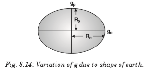
The equatorial radius is about 21 km longer than polar radius.

Therefore, the weight of body increases as it is taken from equator to the pole.
8.10. ROCKETS

Spacecraft Propulsion
Spacecraft Propulsion is characterized in general by its complete integration within the spacecraft (e.g. satellites). Its function is to provide forces and torques in (empty) space to:
• transfer the spacecraft: used for interplanetary travel
• position the spacecraft: used for orbit control
• orient the spacecraft: used for altitude control

The jet propulsion systems for launching rockets are also called primary propulsion systems. Spacecrafts, e.g. satellites, are operated by secondary propulsion systems.
Characteristics of Spacecraft Propulsion Systems
In order to fulfill altitude and orbit operational requirements of spacecraft, spacecraft propulsion systems are characterized by:
• Very high velocity increment capability (many km/s)
• Low thrust levels (1 mN to 500 N) with low acceleration levels
• Continuous operation mode for orbit control
• Pulsed operation mode for altitude control
• Predictable, accurate and repeatable performance (impulse bits)
• Reliable, leak-free long time operation (storable propellants)
• Minimum and predictable thrust exhaust impingement effects
Classification of Propulsion Systems
Spacecraft propulsion can be classified according to the source of energy utilized for the ejection of propellant:
• Chemical propulsion use heat energy produced by a chemical reaction to generate gases at high temperature and pressure in a combustion chamber. These hot gases are accelerated through a nozzle and ejected from the system at a high exit velocity to produce thrust force.
• Electric propulsion uses electric or electromagnetic energy to eject matter at high velocity to produce thrust force.
• Nuclear propulsion uses energy from a nuclear reactor to heat gases which are then accelerated through a nozzle and ejected from the system at a high exit velocity to produce thrust force.
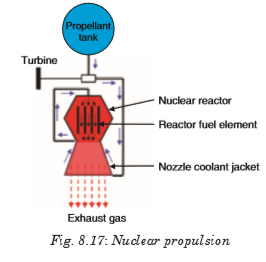
Notes:
• While chemical and electric systems are used for the propulsion of today’s spacecrafts, nuclear propulsion is still under study. Therefore, only chemical and electric propulsion will be dealt with in this book.
8.12. SATELLITES
A satellite is an artificial or a natural body placed in orbit round the earth or another planet in order to collect information or for communication. Communication satellites are satellites that are used specifically to communicate. Part of that communication will be the usual commands and signals we get from any satellite. The payload of the satellite consists of huge collection of powerful radio transmitters and a big dish or something like that, to enable it to talk to things on the ground. And we’ll use them to transmit TV signals, to transmit radio signals, and in some cases, it might be to be transmit internet signals. So, all of that gets turned into radio somehow and transmitted up into space and then bounced back down somewhere else.
There is only one main force acting on a satellite when it is in orbit, and that is the gravitational force exerted on the satellite by the Earth. This force is constantly pulling the satellite towards the center of the Earth.
A satellite doesn’t fall straight down to the Earth because of its velocity. Throughout a satellite’s orbit there is a perfect balance between the gravitational force due to the Earth, and the centripetal force necessary to maintain the orbit of the satellite.
8.12.1. Orbital Velocity of Satellite.

Orbital velocity of a satellite is the velocity required to put the satellite into its orbit around the earth. For revolution of satellite around the earth, the gravitational pull provides the required centripetal force.

Notes:
• Orbital velocity is independent of the mass of the orbiting body and is always along the tangent of the orbit, i.e. satellites of different masses have the same orbital velocity, if they are in the same orbit.
• Orbital velocity depends on the mass of central body and radius of orbit.
• For a given planet, greater the radius of orbit, lesser will be the orbital velocity of the satellite

• Orbital velocity of the satellite when it revolves very close to the surface of the planet:

• Close to the surface of planet,


It means that if the speed of a satellite orbiting close to the earth is made
 times (or increased by 41%) then it will escape from the gravitational field.
 • If the gravitational force of attraction of the sun on the planet varies as
 then the orbital velocity varies as:
EXAMPLE 8.10:
Two satellites A and B go round a planet P in circular orbits having radii 4R and R respectively. If the speed of the satellite A is 3V, what is the speed of the satellite B?

EXAMPLE 8.11:
A satellite is moving around the earth with speed v in a circular orbit of radius r. If the orbit radius is decreased by 1%, what is its speed?

8.12.2. Time Period of Satellite
It is the time taken by satellite to go once around the earth.

Notes:
• From
 , it is clear that time period is independent of the mass of orbiting body and depends on the mass of central body and radius of the orbit.

EXAMPLE 8.12:
A satellite is launched into a circular orbit of radius ‘R’ around earth while a second satellite is launched into an orbit of radius 1.02 R. What is the percentage difference in the time periods of the two satellites?

EXAMPLE 8.13:
What is the periodic time of a satellite revolving above Earth’s surface at a height equal to R, where R is the radius of Earth?

8.12.3. Height of Satellite
As we know, time period of satellite

By squaring and rearranging both sides,


By knowing the value of time period we can calculate the height of satellite the surface of the earth.
EXAMPLE 8.14:
Given radius of earth ‘R’ and length of a day ‘T’, what is the height of a geostationary satellite?


From the expression

EXAMPLE 8.15:
A satellite is revolving round the earth in circular orbit at some height above surface of the earth. It takes 5.26 × 10³ seconds to complete a revolution while its centripetal acceleration is 9.32 m/s2. What is the height of satellite above the surface of earth? (Radius of the earth 6.37 × 10⁶ m)

8.12.4. Geostationary Satellite
The satellite which appears stationary relative to earth is called geostationary or geosynchronous satellite, e.g. communication satellite.
A geostationary satellite always stays over the same place above the earth. Such a satellite is never at rest. It appears stationary due to its zero relative velocity w.r.t. that place on earth.
The orbit of a geostationary satellite is known as the parking orbit.
Notes:
• It should revolve in an orbit concentric and coplanar with the equatorial plane.
• Its sense of rotation should be same as that of earth about its own axis, i.e. in anti-clockwise direction (from west to east).
• Its period of revolution around the earth should be the same as that of earth about its own axis.
 T = 24 hr = 86400 s
• Height of geostationary satellite

Substituting the value of G and M we get R + h = r = 42000 km = 7R
Height of geostationary satellite from the surface of earth, h = 6R = 36000 km • Orbital velocity of geostationary satellite can be calculated by

• Substituting the value of G and M, we get v = 3.08 km/s
8.12.5. Energy of Satellite
When a satellite revolves around a planet in its orbit, it possesses both potential energy (due to its position against gravitational pull of earth) and kinetic energy (due to orbital motion).

Notes
• Kinetic energy, potential energy or total energy of a satellite depends on the mass of the satellite and the central body and also on the radius of the orbit.
• From the above expressions we can say that
Kinetic energy (K) = – (Total energy)
Potential energy (U) = 2 (Total energy)
Potential energy (K) = – 2 (Kinetic energy)

• If the orbit of a satellite is elliptical, then
(a) Total energy
 constant; where a is semi-major axis.
 (b) Kinetic energy (K) will be maximum when the satellite is closest to the central body (at perigee) and maximum when it is farthest from the central body (at apogee).
(c) Potential energy (U) will be minimum when kinetic energy is maximum, i.e. when satellite is closest to the central body (at perigee). Potential energy is maximum when kinetic energy is minimum, i.e. the satellite is farthest from the central body (at apogee).
• Binding Energy: Total energy of a satellite in its orbit is negative. Negative energy means that the satellite is bound to the central body by an attractive force and energy must be supplied to remove it from the orbit to infinity. The energy required to remove the satellite from its orbit to infinity is called Binding Energy of the system, i.e.

EXAMPLE 8.17:
What is the Potential energy of a satellite having mass ‘m’ and rotating at a height of 6.4 × 10⁶ m from the earth’s center?

EXAMPLE 8.18:
Two satellites are moving around the earth in circular orbits at height R and 3R respectively, R being the radius of the earth. What is the ratio of their kinetic energies?

EXERCISE 8-1
1. The distance of Neptune and Saturn from sun are nearly 1013 and 1012 meters respectively. Assuming that they move in circular orbits, what will be their periodic times in the ratio?
2. A spherical planet far out in space has a mass M0 and diameter D0. A particle of mass m falling freely near the surface of this planet will experience an acceleration due to gravity which is equal to g. Derive the expression of g in terms of D.
3. At surface of earth, weight of a person is 72 N. What is his weight at height R/2 from surface of earth (R = radius of earth)?
4. Assuming earth to be a sphere of a uniform density, what is the value of gravitational acceleration in a mine 100 km below the earth’s surface (Given R = 6400 km)?
5. If the gravitational force between two objects was proportional to 1/R; where R is separation between them, then a particle in circular orbit under such a force would have its orbital speed v proportional to which value?
6. An earth satellite S has an orbital radius which is 4 times that of a communication satellite C. What is its period of revolution?
8.13 TYPES AND APPLICATIONS OF SATELLITE SYSTEMS
Four different types of satellite orbits have been identified depending on the shape and diameter of each orbit:
• GEO (Geo-stationary earth orbit)
• MEO (medium earth orbit)
• LEO (Low earth orbit) and
• HEO (Highly elliptical orbit)

GEO (geostationary orbit)
A geostationary orbit or geosynchronous equatorial orbit (GEO) has a circular orbit 35,786 kilometers above the Earth’s equator and following the direction of the Earth’s rotation. An object in such an orbit has an orbital period equal to the Earth’s rotational period (one sidereal day) and thus appears motionless, at a fixed position in the sky, to ground observers.

Most common geostationary satellites are either weather satellites or communication satellites relaying signals between two or more ground stations and satellites that broadcast signals to a large area on the planet. All radio and TV, whether satellite etc. are launched in this orbit.
Advantages of Geo-Stationary Earth Orbit
1. It is possible to cover almost all parts of the earth with just 3 geo satellites.
2. Antennas need not be adjusted every now and then, but can be fixed permanently.
3. The life-time of a GEO satellite is quite high usually around 15 years.
Disadvantages of Geo-Stationary Earth Orbit
1. Larger antennas are required for northern/southern regions of the earth.
2. High buildings in a city limit the transmission quality.
3. High transmission power is required.
4. These satellites cannot be used for small mobile phones.
5. Fixing a satellite at Geo stationary orbit is very expensive.
LEO (Low Earth Orbit)
Satellites in low Earth orbits are normally military reconnaissance satellites that can locate out tanks from 160 km above the

1. The antennas can have low transmission power of about 1 watt.
2. The delay of packets is relatively low.
3. Useful for smaller foot prints
Disadvantages of Low Earth Orbit
1. If global coverage is required, it requires at least 50-200 satellites in this orbit.
2. Special handover mechanisms are required.
3. These satellites involve complex design.
4. Very short life: Time of 5-8 years. Assuming 48 satellites with a life-time of 8 years each, a new satellite is needed every 2 months.
5. Data packets should be routed from satellite to satellite. MEO (Medium Earth Orbit) or ICO (Intermediate Circular Orbit) Medium Earth Orbit satellites move around the earth at a height of 600020000 km above earth’s surface. Their signal takes 50 to 150 milliseconds to make the round trip. MEO satellites cover more earth area than LEOs but have a higher latency. MEOS are often used in conjunction with GEO satellite systems.
Advantages of Medium Earth Orbit
1. Compared to LEO system, MEO requires only a dozen satellites.
2. Simple in design.
3. Requires very few handovers.
Disadvantages of Medium Earth Orbit
1. Satellites require higher transmission power.
2. Special antennas are required.
HEO (Highly Elliptical Orbit)
A satellite in elliptical orbit follows an oval-shaped path. One part of the orbit is closest to the centre of Earth (perigee) and another part is farthest away (apogee). A satellite in this type of orbit generally has an inclination angle of 64 degrees and takes about 12 hours to circle the planet. This type of orbit covers regions of high latitude for a large fraction of its orbital period.

8.14. COSMIC VELOCITY (FIRST, SECOND AND THIRD)
The cosmic velocity is the initial velocity which a body must have to be able to overcome the gravity of another object.
We have:
1. The first cosmic velocity
2. Second cosmic velocity (escape velocity)
3. The third cosmic velocity
4. The fourth cosmic velocity
8.14.1. The first cosmic velocity
As you know the satellites which were sent by a human are orbiting around the Earth. They had to be launched with a very high velocity, namely, with the first cosmic velocity.

This velocity can be calculated using the gravitational force and the centripetal force of the satellite:

Satellites must have extremely high velocity to orbit around the Earth. In fact, satellites go around the Earth at the height h = 160 km in order not to break into the atmosphere.
8.15.2. Second cosmic velocity (escape velocity)
In the previous section we calculated the velocity which a body has to have to go around the Earth, which means that we calculated the value of the first cosmic velocity. Now it is time to give attention to calculating the second cosmic velocity -it is the speed needed to “break free” from the gravitational attraction of the Earth.
In order to understand this issue we should know something about kinetic and potential energy.

This value is calculated using the fact that as the body moves away from the Earth, the kinetic energy decreases and the potential energy increases. At infinity, both the energies are equal to zero, because, when the distance between the body and the Earth increases, the kinetic energy decreases and at infinity, it has the value of 0.
The potential energy at infinity has got the highest value but if we put infinity in the previous formula, we will obtain zero (or an extremely small fraction).
The value of the second cosmic velocity is calculated as follows;

And finally, the practical curiosity.

We can also obtain the value of the second cosmic velocity by multiply the value of the first cosmic velocity by the square root of two.
8.14.3. The third cosmic velocity
The third cosmic velocity is the initial velocity which a body has to have to leave the Solar System and its value is:

At the surface of the Earth, this velocity is about 42 km/s. But due to its revolution, it is enough to launch the body with velocity 16.7 km/s in the direction of this movement.
8.14.4. The fourth cosmic velocity
It is the initial velocity which a body should have to leave the Milky Way.

This velocity is about 350 km/s but since Sun is going around the galaxy center, so it is enough to launch the body with the velocity of 130 km/s in the direction of the Sun’s movement.


1. A satellite A of mass m is at a distance of r from the center of the earth. Another satellite B of mass 2m is at distance of 2r from the earth’s center. What is the ratio of their time periods?
2. Mass of moon is 7.34 × 10²² kg. If the acceleration due to gravity on the moon is 1.4 m/s2, find the radius of moon. Use (G = 6.67 × 10⁻¹¹ Nm2/kg2).
3. A planet has mass 1/10 of that of earth, while radius is 1/3 that of earth. If a person can throw a stone on earth surface to a height of 90 m, to what height will he be able to throw the stone on that planet?
4. If the distance between centers of earth and moon is D and the mass of earth is 81 times the mass of moon, then at what distance from center of earth the gravitational force will be zero?

5. What is the depth d at which the value of acceleration due to gravity becomes
 times the value at the surface? [R = radius of the earth]
6. The distance between center of the earth and moon is 384000 km. If the mass of the earth is 6 × 1024 kg and G = 6.67 × 10⁻¹¹ Nm2/kg2, what is the speed of the moon?
7. One project after deviation from its path, starts moving round the earth in a circular path at radius equal to nine times the radius at earth R, what is its time?
8. A satellite A of mass m is revolving round the earth at a height ‘r’ from the center. Another satellite B of mass 2m is revolving at a height 2r. What is the ratio of their time periods?

Newton’s law of gravitation
This is also called the universal law of gravitation or inverse square law. And sates that “the gravitational force of attraction between two masses m1 and m2 is directly proportional to the product of masses and inversely proportional to the square of their mean distance apart.”

Kepler’s laws of planetary motion
1st Law: This law is called the law of orbits and states that planets move in ellipses with the sun as one of their foci. It can also be stated that planets describe ellipses about the sun as one focus.
2nd Law: This is called the law of areas and states that the line joining the sun and the planet sweeps out equal areas in equal periods of time.
3rd Law: The law of periods states that the square of the periods T of revolution of planets are proportional to the cubes of their mean distances R from the sun.

Verification of Kepler’s third law of planetary motion
Gravitational force of attraction of the sun and the planet

Centripetal force responsible for keeping the planet moving in a circular motion around the sun.

Acceleration due to gravity at the surface of the earth
At the surface of the earth acceleration due to gravity is given by;

This value is constant and it’s average value is taken to be 9.8 m/s2
Variation of acceleration due to gravity with height
The acceleration due to gravity at a point above the surface of the earth is given by;

This value decreases as you move further from the surface of the earth.
Variation of gravity with depth
At a point below the surface of the earth, acceleration due to gravity is given by;

The depth d is measured from the surface of the earth. The value of acceleration due to gravity increases as we move towards the surface. At center of earth g = 0.
Variation in g Due to Rotation of Earth
As the earth rotates, a body placed on its surface moves along the circular path and hence experiences centrifugal force, due to which the apparent weight of the body decreases.
By solving, the acceleration due to gravity is given by;

Variation of gravity g Due to Shape of Earth
The value of acceleration due to gravity will vary depending on someone’s position at the surface of the earth as;

Rockets and spacecraft
A rocket is a device that produces thrust by ejecting stored matter. Spacecraft Propulsion is characterized in general by its complete integration within the spacecraft (e.g. satellites).
Satellites
A satellite is an artificial body placed in orbit round the earth or another planet in order to collect information or for communication.
Orbital Velocity of Satellite

Time Period of Satellite
The period of a satellite is given by;

Height of Satellite
The height atIt is seen that angular momentum of satellite depends on both the mass of orbiting and central body as well as the radius of orbit. Energy of Satellite When a satellite revolves around a planet in its orbit, it possesses both potential energy (due to its position against gravitational pull of earth) and kinetic energy (due to orbital motion). which a satellite is launched is given by;

Geostationary Satellite
The satellite which appears stationary relative to earth is called geostationary or geosynchronous satellite e.g. communication satellite.
Angular Momentum of Satellite
The angular momentum of a satellite is given by;

It is seen that angular momentum of satellite depends on both the mass of orbiting and central body as well as the radius of orbit.
Energy of Satellite
When a satellite revolves around a planet in its orbit, it possesses both potential energy (due to its position against gravitational pull of earth) and kinetic energy (due to orbital motion).

Types and applications of Satellite Systems
• GEO (Geo-stationary earth orbit)
• MEO (medium earth orbit)
• LEO (Low earth orbit) and
• HEO (Highly elliptical orbit)
Cosmic velocity
The first cosmic velocity

Second cosmic velocity
This is also called the escape velocity,

Third cosmic velocity
The third cosmic velocity is the initial velocity which a body has to have to escape the Solar System and its value is given by;

At the surface of the Earth, this velocity is about 42 km/s. But due to its revolution, it is enough to launch the body with velocity 16.7 km/s in the direction of this movement.
8.14.4. The fourth cosmic velocity
It is the initial velocity which a body should have to leave the Milky Way.
v4 = 130 km/s
This velocity is about 350 km/s but since Sun is going around the galaxy center, so it is enough to launch the body with the velocity of 130 km/s in the direction of the Sun’s movement.

Using the Across and Down clues, write the correct words in the numbered grid below.

ACROSS
1.The only natural satellite of Earth.
5. An object in orbit around a planet.
6. The smallest planet and farthest from the Sun.
7. This planet probably got this name due to its red color and is sometimes referred to as the Red Planet.
9. This planet’s blue color is the result of absorption of red light by methane in the upper atmosphere.
10. It is the brightest object in the sky except for the Sun and the Moon.
DOWN
2. Named after the Roman god of the sea.
3. The closest planet to the Sun and the eighth largest.
4. A large cloud of dust and gas which escapes from the nucleus of an active comet.
8. The largest object in the solar system.

1. A satellite A of mass m is at a distance of r from the center of the earth. Another satellite B of mass 2m is at distance of 2r from the earth’s center. What is the ratio of their time periods?
2. Mass of moon is 7.34 × 10²² kg. If the acceleration due to gravity on the moon is 1.4 m/s2, find the radius of moon. Use (G = 6.67 × 10⁻¹¹ Nm2/kg2).
3. A planet has mass 1/10 of that of earth, while radius is 1/3 that of earth. If a person can throw a stone on earth surface to a height of 90 m, to what height will he be able to throw the stone on that planet?

5. What is the depth d at which the value of acceleration due to gravity becomes
 times the value at the surface? [R = radius of the earth]
6. The distance between center of the earth and moon is 384000 km. If the mass of the earth is 6 × 1024 kg and G = 6.67 × 10⁻¹¹ Nm2/kg2, what is the speed of the moon?
7. One project after deviation from its path, starts moving round the earth in a circular path at radius equal to nine times the radius at earth R, what is its time?
8. A satellite A of mass m is revolving round the earth at a height ‘r’ from the center. Another satellite B of mass 2m is revolving at a height 2r. What is the ratio of their time periods?

Newton’s law of gravitation
This is also called the universal law of gravitation or inverse square law. And sates that “the gravitational force of attraction between two masses m1 and m2 is directly proportional to the product of masses and inversely proportional to the square of their mean distance apart.”

Kepler’s laws of planetary motion
1st Law: This law is called the law of orbits and states that planets move in ellipses with the sun as one of their foci. It can also be stated that planets describe ellipses about the sun as one focus.
2nd Law: This is called the law of areas and states that the line joining the sun and the planet sweeps out equal areas in equal periods of time.
3rd Law: The law of periods states that the square of the periods T of revolution of planets are proportional to the cubes of their mean distances R from the sun.

Verification of Kepler’s third law of planetary motion
Gravitational force of attraction of the sun and the planet

Centripetal force responsible for keeping the planet moving in a circular motion around the sun.

Acceleration due to gravity at the surface of the earth
At the surface of the earth acceleration due to gravity is given by;

This value is constant and it’s average value is taken to be 9.8 m/s2
Variation of acceleration due to gravity with height
The acceleration due to gravity at a point above the surface of the earth is given by;

This value decreases as you move further from the surface of the earth.
Variation of gravity with depth
At a point below the surface of the earth, acceleration due to gravity is given by;

The depth d is measured from the surface of the earth. The value of acceleration due to gravity increases as we move towards the surface. At center of earth g = 0
Variation in g Due to Rotation of Earth
As the earth rotates, a body placed on its surface moves along the circular path and hence experiences centrifugal force, due to which the apparent weight of the body decreases. By solving, the acceleration due to gravity is given by; .

Variation of gravity g Due to Shape of Earth
The value of acceleration due to gravity will vary depending on someone’s position at the surface of the earth as;

Rockets and spacecraft
A rocket is a device that produces thrust by ejecting stored matter. Spacecraft Propulsion is characterized in general by its complete integration within the spacecraft (e.g. satellites).
Satellites
A satellite is an artificial body placed in orbit round the earth or another planet in order to collect information or for communication.
Orbital Velocity of Satellite

Time Period of Satellite
The period of a satellite is given by;

Height of Satellite
The height at which a satellite is launched is given by;

Geostationary Satellite
The satellite which appears stationary relative to earth is called geostationary or geosynchronous satellite e.g. communication satellite.
Angular Momentum of Satellite
The angular momentum of a satellite is given by;

It is seen that angular momentum of satellite depends on both the mass of orbiting and central body as well as the radius of orbit.
Energy of Satellite
When a satellite revolves around a planet in its orbit, it possesses both potential energy (due to its position against gravitational pull of earth) and kinetic energy (due to orbital motion).

Types and applications of Satellite Systems
• GEO (Geo-stationary earth orbit)
• MEO (medium earth orbit)
• LEO (Low earth orbit) and
• HEO (Highly elliptical orbit)
Cosmic velocity
The first cosmic velocity

Second cosmic velocity
This is also called the escape velocity,

Third cosmic velocity
The third cosmic velocity is the initial velocity which a body has to have to escape the Solar System and its value is given by;

Unit 9: ATOMIC MODELS AND PHOTOELECTRIC EFFECT
Unit 9: ATOMIC MODELS AND PHOTOELECTRIC EFFECT
Topic Area: ATOMIC PHYSICS
Sub-Topic Area: QUANTUM PHYSICS
Key unit competence: By the end of this unit I should be able to evaluate the atomic model and photoelectric effect
Unit Objectives:
By the end of this unit learners will be able to;
◊ describe different atomic models by explaining their concepts and drawbacks.
◊ explain the photoelectric effect and its applications in everyday life.

9.0 INTRODUCTION
An atomic theory is a model developed to explain the properties and behaviors of atoms. An atomic theory is based on scientific evidence available at any given time and serves to suggest future lines of research about atoms.
The concept of an atom can be traced to debate among Greek philosophers that took place around the sixth century B.C. One of the questions that interested these thinkers was the nature of matter. Is matter continuous or discontinuous? If you could break a piece of chalk as long as you wanted, would you ever reach some ultimate particle beyond which further division was impossible? Or could you keep up that process of division forever?
Such questions need the knowledge on the atomic structure and interaction with photoelectric effect to be answered. This theory is helpful in Chemistry (Atomic structure), Security (Alarm systems), Medicine, Archaeology, etc.
9.1 STRUCTURE OF ATOM
An atom is a sphere in which positively charged particles called protons and negatively charged particles called electrons are found/embedded. As the number of protons equals the number of electrons, the atom is said to be neutral. This model is called plum pudding model by J.J Thomson. J.J. Thomson gave the first idea regarding structure of atom. According to this model, an atom is a solid sphere in which entire positive charge and it’s mass is uniformly distributed and negative charges (i.e. electron) are embedded like seeds in watermelon.
Success and failure
Thomson’s model explained the phenomenon of thermionic emission, photoelectric emission and ionization. The model fails to explain the scattering of a-particles and it is the origin of spectral lines observed in the spectrum of hydrogen and other atoms.
9.2 RUTHERFORD’S ATOMIC MODEL
Rutherford performed experiments on the scattering of alpha particles by extremely thin gold foils and made the following observations;

It was observed that:
• Some of a-particles are deflected through small angles.
• A few a-particles (1 in 1000) are deflected through the angle more than 90°.
• A few a-particles (very few) returned back i.e. deflected by 180°.
• Distance of closest approach (Nuclear dimension) is the minimum distance from the nucleus up to which the a-particle approach. It is denoted by r0. From figure

Equation 9-2 is the equation of kinetic energy of a-particle.

From these experiments a new model of the atom was born called Rutherford’s planetary model of the atom. The following conclusions were made to describe the atomic structure:
• Most of the mass and all of the charge of an atom is concentrated in a very small region called atomic nucleus.
• Nucleus is positively charged and it’s size is of the order of
10–15 m .• In an atom there is maximum empty space and the electrons revolve around the nucleus in the same way as the planets revolve around the sun.
Drawbacks : Rutherford's model could not explain the following:
• Stability of atom: It could not explain the stability of atom because according to classical electrodynamics, an accelerated charged particle should continuously radiate energy. Thus, an electron moving in a circular path around the nucleus should also radiate energy and thus move into and smaller orbits of gradually decreasing radius and it should ultimately fall into nucleus.

• According to this model, the spectrum of atom must be continuous whereas practically it is a line spectrum.
• It did not explain the distribution of electrons outside the nucleus.
9.3 BOHR’S ATOMIC MODEL
Bohr proposed a model for hydrogen atom which is also applicable for some lighter atoms in which a single electron revolves around a stationary nucleus of positive charge Ze (called hydrogen like atom). Bohr’s model is based on the following postulates:
• Each electron moves in a circular orbit centered at the nucleus.
• The centripetal force needed by the electron moving in a circle is provided by electrostatic force of attraction between the nucleus and electrons.
• The angular momenta p of electrons are whole number multiples of
 where h is the Planck’s constant. i.e.
• When electron moves in its allowed orbit, it doesn’t radiate energy. The atom is then stable. Such stable orbits are called stationary orbit.
• When an electron jumps from one allowed orbit to another, it radiates energy. The energy of radiation equals energy difference between levels.

where h is Planck’s constant and f is the frequency of radiation. When electron jumps from higher energy orbit (E1) to lower energy orbit (E2), then difference of energies of these orbits, i.e. E1 – E2 emits in the form of photon. But if electron goes from E2 to E1 it absorbs the same amount of energy.
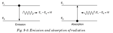
Notes:
• According to Bohr theory, the momentum of an electron revolving in second orbit of H2 atom will be

• For an electron in the nth orbit of hydrogen atom in Bohr model, circumference of orbit =
 = de-Broglie wavelength. Bohr’s Orbits (For Hydrogen and H2-Like Atoms). A: Radius of orbit For an electron around a stationary nucleus, the electrostatics force of attraction provides the necessary centripetal force, i.e.
 Bohr’s Orbits (For Hydrogen and H2-Like Atoms).
A: Radius of orbit
For an electron around a stationary nucleus, the electrostatics force of attraction provides the necessary centripetal force, i.e.


From equation 9-4 and 9-5, radius of nth orbit

Notes:
• The radius of the innermost orbit (n = 1) of hydrogen atom (z = 1) is called Bohr’s radius a0, i.e. a0 = 0.53. 10-10m
B:Speed of electron
From the above relations, speed of electron in nth orbit can be calculated as

where (c = speed of light 3 × 10⁸ m/s).
Notes:
• The ratio of speed of an electron in ground state in Bohr’s first orbit of hydrogen atom to velocity of light in air is equal to

(where c = speed of light in air).
Drawbacks of Bohr’s atomic model
• It is valid only for single valency atoms, e.g. : H, He+2, Li+, Na+1 etc.
• Orbits were taken as circular but according to Sommerfield these are elliptical.
• Intensity of spectral lines could not be explained.
• Nucleus was taken as stationary but it also rotates on its own axis.
• It could not explain the minute structure in spectral lines.
• This does not explain the Zeeman effect (splitting up of spectral lines in magnetic field) and Stark effect (splitting up in electric field)
• This does not explain the doublets in the spectrum of some of the atoms like sodium (5890x10-10m & 5896x 10-10m).
9.4 ENERGY LEVELS AND SPECTRAL LINES OF HYDROGEN
When hydrogen atom is excited, it returns to its normal unexcited state (or ground state) by emitting the energy it had absorbed earlier. This energy is given out by the atom in the form of radiations of different wavelengths as the electron jumps down from a higher orbit to a lower orbit. Transition from different orbits causes different wavelengths. These constitute spectral series which are characteristic of the atom emitting them. When observed through a spectroscope, these radiations are imaged as sharp and straight vertical lines of a single color.

The spectral lines arising from the transition of electron forms a spectra series. Mainly there are five series and each series is named after its discover as Lyman series, Balmer series, Paschen series, Bracket series and Pfund series.
First line of the series is called first member, for which line wavelength is maximum
 Last line of the series (n2 = ∞) is called series limit, for which line wavelength is minimum
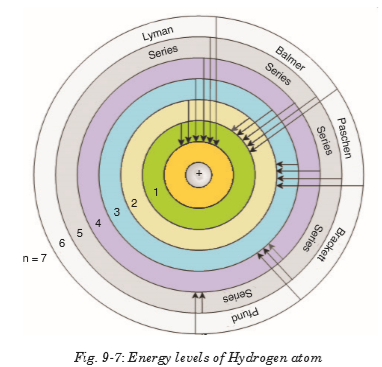
9.5 THERMIONIC EMISSION ( THERMO ELECTRONIC EMISSION)
Thermionic emission means the discharge of electrons from heated materials. It is widely used as a source of electrons in conventional electron tubes (e.g., television picture tubes) in the fields of electronics and communications. The phenomenon was first observed (1883) by Thomas A. Edison as a passage of electricity from a filament to a plate of metal inside an incandescent lamp.

In thermionic emission, the heat supplies some electrons with at least the minimal energy required to overcome the attractive force holding them in the structure of the metal. This minimal energy, called the work function, is the characteristic of the emitting material and the state of contamination of its surface.
9.6 APPLICATIONS OF CATHODE RAYS
9.6.1 Cathode ray oscilloscope
The cathode-ray oscilloscope (CRO) is a common laboratory instrument that provides accurate time and amplitude measurements of voltage signals over a wide range of frequencies. Its reliability, stability and ease of operation makes it suitable as a general purpose laboratory instrument.

The main part of the C.R.O. is a highly evacuated glass tube housing parts which generates a beam of electrons, accelerates them, shapes them into a narrow beam and provides external connections to the sets of plates changing the direction of the beam. The heart of the CRO is a cathode-ray tube shown schematically in Fig.9-10;

Working of a C.R.O
• An indirectly heated cathode provides a source of electrons for the beam by ‘boiling’ them out of the cathode.
• The anode is circular with a small central hole. The potential of anode creates an electric field which accelerates the electrons, some of which emerge from the hole as a fine beam. This beam lies along the central axis of the tube.
• The grid has the main function of concentrating the beam at the centre controlling the potential of the grid that controls the number of electrons for the beam, and hence the intensity of the spot on the screen where the beam hits.
• X and Y are two deflection plates. The X plates are used for deflecting the beam from left to right (the x-direction) by means of the ‘ramp’ voltage. The Y plates are used for deflection of the beam in the vertical direction. Voltages on the X and Y sets of plates determine where the beam will strike the screen and cause a spot of light.
• The screen coated on the inside with a fluorescent material which shines with green light (usually) where the electrons are striking.
9.6.2 TV tubes
The picture tube is the largest component of a television set, consisting of four basic parts. The glass face panel is the screen on which images appear. Suspended immediately behind the panel is a steel shadow mask, perforated with thousands of square holes. (Connected to the mask is a metal shield to neutralize disruptive effects of the Earth’s magnetic field.) The panel is fused to a glass funnel, which comprises the rear of the picture tube. The very rear of the funnel converges into a neck, to which an electron gun assembly is connected.

The inside of the panel is painted with a series of very narrow vertical stripes, consisting of red, green and blue phosphors. These stripes are separated by a narrow black graphite stripe guard band. When struck by an electron beam, the phosphors will illuminate, but the graphite will not. This prevents colour impurity by ensuring that the electron beam only strikes the phosphor stripes it is intended to light. The electron beam is generated by the electron gun assembly, which houses three electron guns situated side-by-side. Each of the three guns emits an electron beam (also called a cathode ray) into the tube, through the mask and onto the panel.

Because the three beams travel side-by-side, the holes in the mask ensure that each beam, because of its different angle of attack, will hit only a specific phosphor stripe; red, green or blue. The three phosphors, lighted in different combinations of intensity, can create any visible colour when viewed from even a slight distance.
The three electron beams are directed across the screen through a series of electromagnets, called a yoke, which draw the beams horizontally across the screen in line at a time. Depending on the screen size, the beam draws about 500 lines across the entire screen. Each time, the phosphors light up to produce an image.
The electron guns and the yoke are electronically synchronized to ensure the lines of phosphors are lighted properly to produce an accurate image. The image lasts only for about a 1/30th of a second. For that reason, the picture must be redrawn 30 times in a second. The succession of so many pictures produces the illusion of movement, just like the frames on movie film.
9.7 FLUORESCENCE AND PHOSPHORESCENCE
Fluorescence is the emission of light by a substance that has absorbed light or other electromagnetic radiation. It is a form of photoluminescence.
In most cases, the emitted light has a longer wavelength, and therefore, lower energy than the absorbed radiation. However, when the absorbed electromagnetic radiation is intense, it is possible for one electron to absorb two photons; this two-photon absorption can lead to emission of radiation having a shorter wavelength than the absorbed radiation. The emitted radiation may also be of the same wavelength as the absorbed radiation, termed “resonance fluorescence”.
Fluorescence occurs when an orbital electron of a molecule or atom relaxes to its ground state by emitting a photon of light after being excited to a higher quantum state by some type of energy. The most striking examples of fluorescence occur when the absorbed radiation is in the ultraviolet region of the spectrum, and thus invisible to the human eye, and the emitted light is in the visible region.
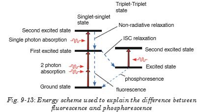
Phosphorescence is a specific type of photoluminescence related to fluorescence. Unlike fluorescence, a phosphorescent material does not immediately re-emit the radiation it absorbs. Excitation of electrons to a higher state is accompanied with the change of a spin state. Once in a different spin state, electrons cannot relax into the ground state quickly because the re-emission involves quantum mechanically forbidden energy state transitions. As these transitions occur very slowly in certain materials, absorbed radiation may be re-emitted at a lower intensity for up to several hours after the original excitation.
9.8 PHOTOELECTRIC EMISSION LAWS
Law 1:
The photocurrent is directly proportional to the intensity of light and is independent of frequency.
Explanation
According to quantum theory, each photon interacts only with each electron. When the intensity is increased more photons will come and they will interact with more electrons. This will increase the amount of photo current.
Law 2:
The kinetic energy of the photoelectrons is directly proportional to frequency and is independent of intensity.
Explanation
According to Einstein’s equation, hf0 is constant. Then kinetic energy is directly proportional to frequency.
Law 3:
Photoelectric effect does not happen when the incident frequency is less than a minimum frequency (threshold frequency).
Explanation
From Einstein’s equation, if , then kinetic energy becomes negative and it is impossible, in other words photoelectric effect does not happen.
Law 4:
There is no time lag between the incidence of photon and emission of electrons. Thus, photoelectric process is instantaneous.
Explanation
According to quantum theory, each photon interacts with each electron. So different electrons will interact with different photons at same instant. Thus there is no time lag between incidence and emission.
9.9 PHOTOELECTRIC EFFECT
The photoelectric effect is the emission of electrons from the surface of a metal when electromagnetic radiation (such as visible or ultraviolet light) shines on the metal. At the time of its discovery, the classical wave model for light predicted that the energy of the emitted electrons will increase as the intensity (brightness) of the light increased. It was discovered that it did not behave that way. Instead of using the wave model, treating light as a particle (photon) led to a more consistent explanation of the observed behavior.

From photon theory, we note that in a monochromatic beam, all photons have the same energy (equal to hf). Increasing the intensity of the light beam means increasing the number of photons in the beam but does not affect the energy of each photon as long as the frequency is not changed.
From this consideration and suggestions of Einstein, the photon theory makes the following predictions:
1. For a given metal and frequency of incident radiation, the number of photoelectrons ejected per second is directly proportional to the intensity of the incident light.
2. For a given metal, there exists a certain minimum frequency (f0) of incident radiation below which no emission of photoelectrons takes place. This frequency is called the threshold frequency or cutoff frequency.
3. Above the threshold frequency, the maximum kinetic energy of the emitted photoelectron is independent of the intensity of the incident light but depends only upon the frequency (or wavelength) of the incident light.
4. The time lag between the incidence of radiation and the emission of a photoelectron is very small (less than 10-9 second). This is evidence of the particle nature of light.
9.10 FACTORS AFFECTING PHOTOELECTRIC EMISSION
Photoelectric current is produced as a result of photoelectric effect. Therefore, understanding the factors which influence the photoelectric effect is very important. The previous studies on photoelectric effect have presented the following factors which may have a direct impact on photoelectric effect.
Intensity of Light:
If a highly intense light of frequency equal to or greater than threshold frequency falls on the surface of matter, the photoelectric effect is caused. Studying the impact of this factor is the focus of this research study. One thing which is very clear is that the emission of electrons does not depend upon the intensity of light unless the frequency of light is greater than the threshold frequency. The threshold frequency varies from matter to matter.
Number of Photoelectrons:
The increase in intensity of light increases the number of photoelectrons, provided the frequency is greater than threshold frequency. In short, the number of photoelectrons increases the photoelectric current.
Kinetic Energy of Photoelectrons:
The kinetic energy of photoelectrons increases when light of high energy falls on the surface of matter. When energy of light is equal to threshold energy, then electrons are emitted from the surface, whereas when energy is greater than threshold energy, then photoelectric current is produced. The threshold frequency is not same for all kinds of matter and it varies from matter to matter.
9.11 PHOTON, WORK FUNCTION AND PLANCK'S CONSTANT
The photon is the fundamental particle of visible light. In some ways, visible light behaves like a wave phenomenon, but in other respects it acts like a stream of high-speed, submicroscopic particles.
Minimum amount of energy which is necessary to start photo electric emission is called Work Function. If the amount of energy of incident radiation is less than the work function of metal, no photo electrons are emitted.
Planck’s constant describes the behavior of particles and waves on the atomic scale. The idea behind its discovery, that energy can be expressed in discrete units, or quantized, proved fundamental for the development of quantum mechanics.
Planck introduced the constant (h = 6.63 × 10⁻³⁴ J.s) in his description of the radiation emitted by a blackbody (a perfect absorber of radiant energy). The constant’s significance, in this context, was that radiation (light, for example) is emitted, transmitted and absorbed in discrete energy packets.
Project 9-1: Photoelectric Effect
Aim: this project aims at gaining the deep knowledge on photoelectric effect.
Question: Describe the observations made of the photoelectric effect and how this supports the particle model and wave model of light studied in unit 1.
Hypothesis: write a hypothesis on the phenomenon of photoelectric effect.
Procedure
1. State the main principle of photoelectric effect.
2. Outline your observations on different conditions
Collecting Data
Use internet and textbooks to analyze the phenomenon of photoelectric effect.
Report design
Write your report of at least five supporting points including the one given in the format below:

9.12 EINSTEIN’S EQUATION
According to Einstein’s theory, an electron is ejected from the metal by a collision with a single photon. In the process, all the photon energy is transferred to the electron and the photon ceases to exist. Since electrons are held in the metal by attractive forces, a minimum energy (W0) is required just to get an electron out through the surface. W0 is called the work function, and is a few electron volts (1eV = 1.6 × 10⁻¹⁹ J ) for most metals.
Definitions
Photoelectric emission is the phenomenon of emission of electrons from the surface of metals when the radiations of suitable frequency and suitable wavelength fall on the surface of the metal.
Work function is the minimum energy required to set free an electron from the binding forces on the metal surface.
The Threshold Frequency is defined as the minimum frequency of incident light required for the photoelectric emission.
If the frequency f of the incoming light is so low that hf is less than W0, then the photons will not have enough energy to eject any electrons at all. If hf > W0, then electrons will be ejected and energy will be conserved in the process.
So Einstein suggested that the energy of the incident radiation hf was partly used to free electrons from the binding forces on the metal and the rest of the energy appeared as kinetic energy of the emitted electrons. This is stated in the famous Einstein’s equation of photoelectric effect as stated in equation 9-7 below.

Equation 9-8 is called the Einstein’s photoelectric equation.
Many electrons will require more energy than the bare minimum W0 to get out of the metal, and thus the kinetic energy of such electrons will be less than the maximum.
ACTIVITY 9-1:Einstein Photoelectric Equation
Match the mathematical symbols and their descriptions

Stopping potential The circuit is exposed to radiations of light of frequency f and the supply of potential difference V is connected as shown in Fig.9-15 below. The cathode C is connected at the positive terminal of the supply and the anode P is connected on the negative terminal of the supply.
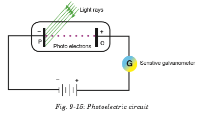
If the circuit is exposed to radiations with the battery reversed as shown in Fig. 9-16, current reduces due to the fact that all electrons emitted are not able to reach the anode P. If this potential difference is increased until no electron reaches the anode P, no current flows and this applied potential is called a stopping potential.

For this case, the kinetic energy of electrons is given by;

where e is electron charge and Vs is the stopping potential. So, equation 9-7 becomes;


EXAMPLE 9-1
The work function for lithium is 4.6 × 10⁻¹⁹ J.
(a) Calculate the lowest frequency of light that will cause photoelectric emission.
(b) What is the maximum energy of the electrons emitted when the light of
frequency 7.3 × 10¹⁴ Hz is used?
EXAMPLE 9-2
Selenium has a work function of 5.11 eV. What frequency of light would just eject electrons?

EXERCISE 9-1
1. Complete table 1 below.
2. The stopping potential when a frequency of 1.61 × 10¹⁵ Hz is incident on a metal is 3 V.
(a) What is energy transferred by each photon?
(b) Calculate the work function of the metal.
(c) What is the maximum speed of the ejected electrons?

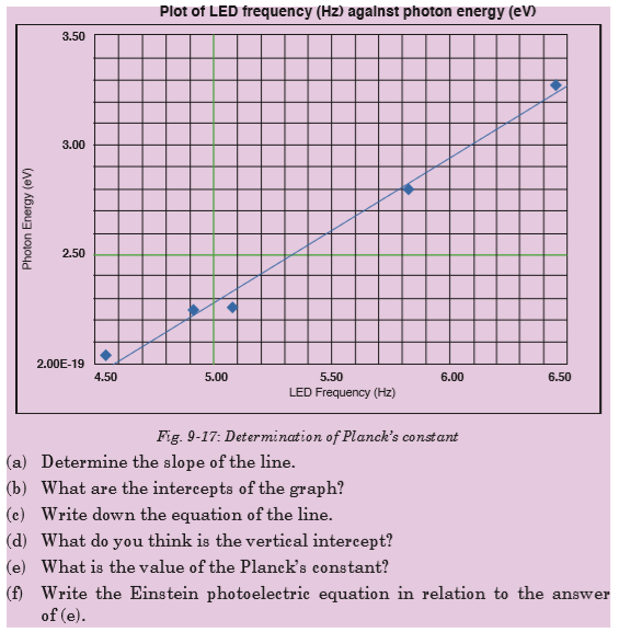
9.13 APPLICATION OF PHOTOELECTRIC EFFECT (PHOTO EMISSIVE AND PHOTOVOLTAIC CELLS)
Photoelectric effect is applied in photoelectric cells or simply photocells. These cells change light energy into electric current. Photoelectric cell makes use of photoelectric effect and hence converts light energy into electrical energy. The strength of the current depends on the intensity of light falling on the cathode.
A photocell consists of an evacuated tube which is transparent to radiations falling on it. It contains two electrodes; a semi-cylindrical cathode coated with photosensitive material and an anode consisting of a straight wire or loop.

When radiations fall on the cathode, photoelectrons are emitted which are collected by the anode if it is positive with respect to the cathode. They, then, go through the external circuit causing electric current. As intensity of radiations increases, the number of electrons emitted by photoelectric effect also increases. Hence current also increases.
An everyday example is a solar powered calculator and a more exotic application would be solar panels and others.
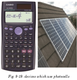
9.14 COMPTON EFFECT
Convincing evidence that light is made up of particles (photons) and photons have momentum can be seen when a photon with high energy hf collided with a stationary electron. Compton effect says that when x-rays are projected on the target, they are scattered after hitting the target and change the direction they were moving. This means that as a photon interacts with a free electron, the process of photon absorption is forbidden by conservation laws, but the photon scattering may occur. If the electron was originally at rest, then, as a result of interaction, it acquires a certain velocity.
The energy conservation laws require that the photon energy decreases by the value of the electron kinetic energy, which means that its frequency must also decrease. At the same time, from the viewpoint of the wave theory, the frequency of scattered light must coincide with the frequency of incident light.
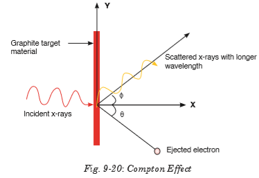
The momentum of the photon can be calculated as follows;

The photon scattering on an electron can be considered as an elastic collision of two particles obeying the energy and momentum conservation laws

1. Describe briefly the two conflicting theories of the structure of the atom.
2. Why was the nuclear model of Rutherford accepted as correct?
3. What would have happened if neutrons had been used in Rutherford’s experiment? Explain your answer.
4. What would have happened if aluminium had been used instead of gold in the alpha scattering experiment? Explain your answer.
5. What three properties of the nucleus can be deduced from the Rutherford scattering experiment? Explain your answer.
6. Monochromatic light of wavelength 560 nm incident on a metal surface in a vacuum photocell causes a current through the cell due to photoelectric emission from the metal cathode. The emission is stopped by applying a positive potential of 1.30 V to the cathode with respect to the anode. Calculate:
(a) the work function of the metal cathode in electron volts.
(b) the maximum kinetic energy of the emitted photoelectrons when the cathode is at zero potential.
7. In a Compton scattering experiment, the wavelength of scattered X-rays for scattering angle of 45 degree is found to be 0.024 angstrom.
(a) What is the wavelength of the incident photon?
(b) What is the percentage change in the wavelength on Compton scattering
8. You use 0.124-nm x-ray photons in a Compton-scattering experiment.
(a) At what angle is the wavelength of the scattered x-rays 1.0% longer than that of the incident x-rays?
(b) At what angle is it 0.050% longer?
9. (a) What is the energy in joules and electron volts of a photon of 420nm violet light?
(b) What is the maximum kinetic energy of electrons ejected from calcium by 420-nm violet light, given that the binding energy (or work function) of electrons for calcium metal is 2.71 eV?
10. An electron and a positron, initially far apart, move towards each other with the same speed. They collide head-on, annihilating each other and producing two photons. Find the energies, wavelengths and frequencies of the photons if the initial kinetic energies of the electron and positron are
(a) both negligible and
(b) both 5.000 MeV. The electron rest energy is 0.511 MeV.
11. (a) Calculate the momentum of a visible photon that has a wavelength of 500 nm.
(b) Find the velocity of an electron having the same momentum.
(c) What is the energy of the electron, and how does it compare with the energy of the photon?
12. For an electron having a de Broglie wavelength of 0.167 nm (appropriate for interacting with crystal lattice structures that are about this size):
(a) Calculate the electron’s velocity, assuming it is non-relativistic.
(b) Calculate the electron’s kinetic energy in eV.
13. When a certain photoelectric surface is illuminated with light of different wavelengths, the following stopping potentials are observed:

Plot the stopping potential on the vertical axis against the frequency of the light on the horizontal axis. Determine;
(a) the threshold frequency;
(b) the threshold wavelength;
(c) the photoelectric work function of the material (in electron volts);
(d) the value of Planck’s constant h (assuming that the value of e is known).
14. The human eye is most sensitive to green light of wavelength 505 nm. Experiments have found that when people are kept in a dark room until their eyes adapt to the darkness, a single photon of green light will trigger receptor cells in the rods of the retina.
(a) What is the frequency of this photon?
(b) How much energy (in joules and electron volts) does it deliver to the receptor cells?
(c) To appreciate what a small amount of energy this is, calculate how fast a typical bacterium of mass 9.5 × 10⁻¹² g would move if it had that much energy?
15. The photoelectric work function of potassium is 2.3 eV. If light having a wavelength of 250 nm falls on potassium, find
(a) the stopping potential in volts;
(b) the kinetic energy in electron volts of the most energetic electrons ejected;
(c) the speed of these electrons.
16. Describe the photoelectric effect and discuss why the wave theory of light cannot account for it.
17. Explain how the quantum theory of light accounts for the photoelectric effect.
18. Compare the quantum and wave theories of light and discuss why both are needed.
19. Give the basic ideas of the Bohr model of the atom and show how they follow from the wave nature of moving electrons. 20. Define quantum number, energy level, ground state, and excited state.

Structure of atom
An atom is a sphere in which positively charged particles called protons and negatively charged particles called electrons are embedded.
Rutherford’s atomic
model Rutherford performed experiments by the scattering of alpha particles on extremely thin gold foils. From these experiments, a new model of the atom called Rutherford’s planetary model of the atom was born. The following conclusions were made as regard as atomic structure:
• Most of the mass and all of the charge of an atom concentrated in a very small region which is called atomic nucleus.
• Nucleus is positively charged and its size is of the order of 10–15 m ≈ 1 Fermi.
• In an atom, there is maximum empty space and the electrons revolve around the nucleus in the same way as the planets revolve around the sun.
Bohr’s atomic
model Bohr’s model is based on the following postulates:
• Each electron moves in a circular orbit centered at the nucleus.
• The centripetal force needed to the electron moving in a circle is provided by electrostatic force of attraction between the nucleus and electrons.
• The angular momenta of electrons are whole number multiples of

where h is the Planck number.
• When electron moves in its allowed orbit, it doesn’t radiate energy. The atom is then stable, such stable orbits are called stationary orbits.
• When an electron jumps from one allowed orbit to another it radiates energy. The energy of radiation equals energy difference between levels. hf = Ei – Ef
Energy levels and spectral lines of Hydrogen
When hydrogen atom is excited, it returns to its normal unexcited (or ground state) state by emitting the energy it had absorbed earlier. Transition from different orbits cause different wavelengths. These constitute spectral series which are characteristic of the atom emitting them. The spectral lines arising from the transition of electron forms a spectra series. Mainly there are five series and each series is named after its discover as Lyman series, Balmer series, Paschen series, Brackett series and Pfund series.
Thermionic emission
Thermionic emission or discharge of electrons from heated materials, is widely used as a source of electrons in conventional electron tubes (e.g., television picture tubes) in the fields of electronics and communications.
Applications of cathode rays
• Cathode ray oscilloscope
• TV tubes
Fluorescence and phosphorescence
Fluorescence is the emission of light by a substance that has absorbed light or other electromagnetic radiation.
Phosphorescence is a specific type of photoluminescence related to fluorescence. Unlike fluorescence, a phosphorescent material does not immediately re-emit the radiation it absorbs.
Photoelectric emission laws’
Law 1: The photo current is directly proportional to the intensity of light and is independent of frequency.
Law 2: The kinetic energy of the photo electrons is directly proportional to frequency and is independent of intensity.
Law 3: Photoelectric effect does not happen when the incident frequency is less than a minimum frequency (threshold frequency).
Law 4: There is no time lag between the incidence of photon and emission of electrons.
Photoelectric effect
The photoelectric effect is the emission of electrons from the surface of a metal when electromagnetic radiation (such as visible or ultraviolet light) shines on the metal.
Factors affecting photoelectric emission
• Intensity of Light:
• Frequency:
• Number of Photoelectrons
• Kinetic Energy of Photoelectrons
Einstein’s equation photoelectric effect
Einstein suggested that the energy of the incident radiation hf was partly used to free electrons from the binding forces on the metal and the rest of the energy appeared as kinetic energy of the emitted electrons and his famous equation is;

If the reverse potential difference applied on the circuit is increased until no electron reaches the anode, no current flows and this applied potential is called a stopping potential. This changes the Einstein’s photoelectric equation to;

Application of photoelectric effect
Photoelectric effect is applied in photoelectric cells or simply photocells. These cells change light energy into electric current. Photoelectric cell makes use of photoelectric effect and hence converts light energy into electrical energy. The strength of the current depends on the intensity of light falling on the cathode.
Compton effect
Compton effect says that when x-rays are projected on the target, they are scattered after hitting the target and change the direction they were moving.
The Compton equation (or Compton shift) is given by;

Unit 10: ANALOG AND DIGITAL SIGNALS
Unit 10: ANALOG AND DIGITAL SIGNALS
Topic Area: DIGITAL TECHNOLOGY
Sub-Topic Area: ANALOG AND DIGITAL SIGNALS
Key unit competence: By the end of this unit I should be able to differentiate analog from digital signals.
Unit Objectives:
By the end of this unit learners will be able to;
◊ explain the transmission of information in a communication system.
◊ explain with examples the use of digital and analog signals in everyday applications
10.1 INTRODUCTION
A signal is any kind of physical quantity that conveys information. Audible speech is certainly a kind of signal, as it conveys the thoughts (information) of one person to another through the physical medium of sound. Hand gestures are signals too. This text is another kind of signal, interpreted by your English-trained mind as information about electric circuits. In this unit, the word signal will be used primarily in reference to an electrical quantity of voltage or current that is used to represent or signify some other physical quantity.
A communication system is made up of devices that employ one of two communication methods (wireless or wired), different types of equipment (portable radios, mobile radios, base/fixed station radios and repeaters) accessories (examples include speaker microphones, battery eliminators and carrying cases) and/or enhancements (encryption, digital communications, security measures, and networking) to meet the user needs.
The most common processing of a signal in a communication system consists of passing the signal through a linear time-invariant system. In this context, such a system is often spoken of as a “filter”. These systems are usually applied to reduce some undesirable components in the signal, to compensate for some undesirable distortion of the signal, or to accentuate some characteristic of a signal. This unit discusses digital and analog signals and their use in modern communication.
10.2 INFORMATION TRANSMISSION IN A COMMUNICATION SYSTEM
A communication system comprises of three sections or parts; transmitting end, propagation medium and receiving end. This is shown on Fig. 10.1 below.
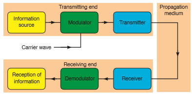
The modulated signal is sent along a channel in the propagating medium by a transmitter. The propagation medium is a channel through which information is transmitted. This may be a cable or free space. At the receiving end, the receiver may have to select and perhaps amplify the modulated signal before the demodulator extracts from it the information signal for delivery to the receptor of information.
A propagation or transmission medium can be classified as;
Linear medium: if different waves at any particular point in medium can be superposed.
Bounded medium: if it is finite in extent, otherwise unbound.
Uniform medium or homogeneous medium: if its physical properties are unchanged at different points.
Isotropic medium: if its physical properties are the same in different directions.
10.3 COMMUNICATION TERMS AND CONCEPTS

1. Communication is the process of sharing the messages through continuous flow of symbols.
2. Communicators (Sender/receiver) are the participants in communication. Typically the roles reverse regularly.
3. Message is a single uninterrupted verbal or nonverbal utterance.
4. Code means a system suitable for creating/carrying messages through a specific medium.
• encode (put into code) and
• decode (take out of code)
5. Channels (verbal, nonverbal, etc.) means the specific mechanism (“pipeline”) used to transmit the message.
6. Mode of communication (face-to-face, television, web, phone, etc.) - form or technology of transmission— determines kind of code used.
7. Noise - interference with message — external (physical), internal (mental) or semantic (misunderstanding/reaction).
8. Environment (part of context) - is that which surrounds and provides a basis for the meaning of a message:
• Physical (surroundings)
• Temporal (point in time)
• Relational (the existing relationship between communicators - friends, strangers, etc.)
• Cultural (language and behaviour of community and the communicator(s) come from)
9. Feedback - checks effects of messages
• positive feedback eg. “keep doing what you’re doing”
• negative feedback eg. “change what you’re doing”.
10. Levels (contexts) of Communication
• Intrapersonal
• Interpersonal
• Public Communication
• Mass Communication (non-interactive)
• Computer Mediated Communication (interactive)
10.4 ELEMENTS OF COMMUNICATION

Sender
The sender is a party that plays the specific role of initiating communication. To communicate effectively, the sender must use effective verbal as well as nonverbal techniques. Such as:-
• Speaking or writing clearly.
• Organizing your points to make them easy to follow and understand.
• Maintaining eye contact.
• Using proper grammar.
• Giving accurate information.
All the above components are essential in the effectiveness of your message. One will lose the audience if it becomes aware of obvious oversights on ones part. The sender should have some understanding of who the receiver is, in order to modify the message to make it more relevant.
Receiver
The receiver means the party to whom the sender transmits the message. A receiver can be one person or an entire audience of people. In the basic communication model, the receiver is directly connected with the speaker. The receiver can also communicate verbally and nonverbally. The best way to receive a message is:
• To listen carefully.
• Sitting up straight.
• Making eye contact.
• Don’t get distracted or try to do something else while you’re listening.
• Nodding and smiling as you listen.
• Demonstrate that you understand the message.
Message
The message is the most crucial element of effective communication which includes the content a sender conveys to the receiver. A message can come in many different forms, such as an oral presentation, a written document, an advertisement or just a comment. In the basic communication model, the way from one point to another represents the sender’s message travelling to the receiver. The message isn’t necessarily what the receiver perceive it to be. Rather, the message is what the sender intends the message to be. The sender must not only compose the message carefully, but also evaluate the ways in which the message can be interpreted.
Channel
The channel is a medium through which a message travels from the sender to the receiver. The message travels from one point to another via a channel of communication. The channel is a physical medium stands between the sender and receiver.
Many channels or types of communication exist, such as
• The spoken word,
• Radio or television,
• An Internet site or
• Something written, like a book, letter or magazine.
Every channel of communication has its advantages and disadvantages. For example, one disadvantage of the written word, on a computer screen or in a book, is that the receiver cannot evaluate the tone of the message. For this reason, effective communicators should make written word communications clear so receivers don’t rely on a specific tone of voice to convey the message accurately. The advantages of television as a channel for communication include its expansive reach to a wide audience and the sender’s ability to further manipulate the message using editing and special effects.
Feedback
This describes the receiver’s response or reaction to the sender’s message. The receiver can transmit feedback through asking questions, making comments or just supporting the message that was delivered. Feedback helps the sender to determine how the receiver interpreted the message and how it can be improved.
10.5 TYPES OF INFORMATION AND REQUIREMENTS
Constructional/creative information: This includes all information that is used for the purpose of producing something. Before anything can be made, the originator mobilizes his intelligence, his supply of ideas, his know-how, and his inventiveness to encode his concept in a suitable way.
Operational information: All concepts having the purpose of maintaining some “industry” in the widest sense of the word are included under this kind of information. Many systems require operational information in the form of programs for proper functioning. Examples of operational information include:
• the operating system of a computer (eg. DOS programs),
• the program controlling a robot or a process computer,
• warning systems for airplanes and ships,
• the hormonal system of the body
Communication information: This is composed of all other kinds of information, eg. letters, books, phone calls, radio transmissions, bird songs and also the message of the Bible. Aspect of such information does not include the construction of a product, neither it is involved in maintaining some process. The goals are transmission of a message, spreading joy, amusement, instruction and personal confidences.
10.6 SIMPLEX TRANSMISSION
Simplex transmission is a single one-way base band transmission. Simplex transmission, as the name implies, is simple. It is also called unidirectional transmission because the signal travels in only one direction. An example of simplex transmission is the signal sent from the TV station to the home television.
Data in a simplex channel is always one way. Simplex channels are not often used because it is not possible to send back error or control signals to the transmit end.
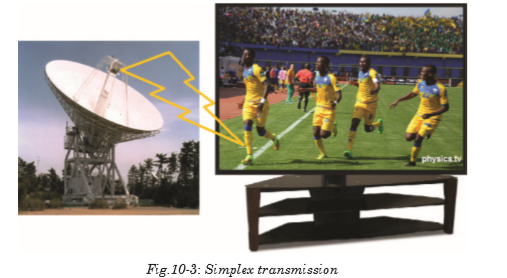
10.7 HALF-DUPLEX COMMUNICATIONS
Half-duplex transmission is an improvement over simplex transmission because the traffic can travel in both directions. Unfortunately, the road is not wide enough to accommodate bidirectional signals simultaneously. This means that only one side can transmit at a time. Two-way radios, such as police or emergency communications mobile radios, work with half-duplex transmissions. If people at both ends try to talk at the same time, none of the transmissions get through.

10.8 FULL-DUPLEX COMMUNICATIONS
Full-duplex transmission operates like a two-way, two-lane street. Traffic can travel in both directions at the same time.
A land-based telephone conversation is an example of full-duplex communication. Both parties can talk at the same time, and the person talking on the other end can still be heard by the other party while they are talking. Although when both parties are talking at the same time, it might be difficult to understand what is being said.
Full-duplex networking technology increases performance because data can be sent and received at the same time. Digital subscriber line (DSL), two-way cable modem, and other broadband technologies operate in full-duplex mode. With DSL, for example, users can download data to their computer at the same time they are sending a voice message over the line.

10.9 BANDWIDTH AND SIGNAL FREQUENCY
Frequency is a parameter that determines how often the sinusoidal signal goes through a cycle. It is usually represented with the symbol f, and it has the unit hertz .

Where T is a periodic time and is measured in seconds.
The bandwidth of a composite signal is the difference between the highest and the lowest frequencies contained in that signal. It is typically measured in hertz, and may sometimes refer to passband bandwidth or baseband bandwidth, depending on context.
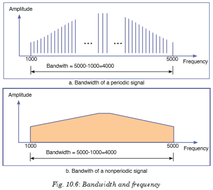
Mathematically, the bandwidth is given by;

Where fUSB and fLSB stand for upper side band and lower side band respectively.
10.10 ANALOG SIGNAL SYSTEM
A system is a physical set of components that take a signal and produces a signal. In terms of engineering, the input is generally some electrical signal and the output is another electrical signal. Analog systems operate with values that vary continuously and have no abrupt transitions between levels. For a long time, almost all electronic systems were analog, as most things we measure in nature are analog. For example, your voice is analogous; it contains an infinite number of levels and frequencies. Therefore, if you wanted a circuit to amplify your voice, an analog circuit seems a likely choice.
In Rwanda recently analog systems were replaced by digital systems that provide greater capacity of data transfer and increased reliability and security.
10.9.1 Example of an analog electronic system
A public address system
A public address system (PA system) is an electronic sound amplification and distribution system with a microphone, amplifier and loudspeakers, used to allow a person to address a large public, for example for announcements of movements at large and noisy air and rail terminals or a sports stadium.

10.11 ANALOG SIGNALS
Analog signal is a continuous signal that contains time varying quantities. An analog signal is a continuous wave denoted by a sine wave and may vary in signal strength (amplitude) or frequency (time). The sine wave’s amplitude value can be seen as the higher and lower points of the wave, while the frequency (time) value is measured in the sine wave’s physical length from left to right.

Analog signal can be used to measure changes in physical phenomenon such as light, sound, pressure, or temperature. For instance, microphone can convert sound waves into analog signal. Even in digital devices, there is typically some analog component that is used to take in information from the external world which will then get translated into digital form –using analog to digital converter.
10.12 ADVANTAGES AND DISADVANTAGES OF ANALOG SIGNALS
Advantages
• Uses less bandwidth than digital sounds.
• More accurate representation of sound.
• It is the natural form of sound.
• Because of editing limitations, there is little someone can do to tinker with the sound, so what you are hearing is the original sound.
Disadvantages
• There are limitations in editing.
• Recording analog sound on tape is expensive.
• It is harder to synchronize analogous sound.
• Quality is easily lost if the tape becomes ruined.
• A tape must always be wound and rewound in order to listen to specific part of sound which can damage it.
• Analog is susceptible to clipping where the highest and lowest notes of a sound are cut out during recording.
10.13 DIGITAL SIGNALS
In electronic signal and information processing and transmission, digital technology is increasingly being used because, in various applications, digital signal transmission has many advantages over analog signal transmission. Numerous and very successful applications of digital technology include the continuously growing number of PC’s, the communication network ISDN as well as the increasing use of digital control stations (Direct Digital Control: DDC).
Unlike analog technology which uses continuous signals, digital technology encodes the information into discrete signal states. When only two states are assigned per digital signal, these signals are termed binary signals. One single binary digit is termed a bit - a contraction for binary digit.
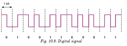
10.14. ADVANTAGES OF DIGITAL TECHNOLOGY
• More capacity from the same number of frequencies; that is, they provide superior Spectral Efficiency. This is a result of the modulation methods used, and the fact that, in many cases more than one ‘conversation’ can be accommodated within a single radio channel.
• Consistent voice clarity at low received signal levels near the edge of coverage. The general consensus is that digital radios provide better audio quality than analog ones. With analog FM radios, the audio quality steadily declines as the received signal strength gets weaker. Digital radios however, will have a consistent audio quality throughout the full service area. The edges of the coverage area in a digital radio system are similar to those experienced with cellular telephones.
• Data is defined in the standard. This means data implementations are no longer proprietary, there are a wide variety of data mechanisms and inter operability can extend into the data domain. With the accepted increase of efficiency by using data communications over voice, this will further increase the usability and effectiveness of digital radio systems.
• Secure transmissions: In digital technologies, data and voice can be secured using encryption without impacting voice quality using industry standard encryption techniques.
10.15 COMPARING DIGITAL AND ANALOG SIGNALS
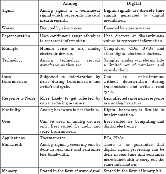


10.16 LOGIC GATES
There are three basic logic gates each of which performs a basic logic function. They are called NOT, AND and OR. All other logic functions can ultimately be derived from combinations of these three. For each of the three basic logic gates a summary is given including the logic symbol, the corresponding truth table and the Boolean expression.

The AND gate is an electronic circuit that gives a high output (1) only if all its inputs are high. A dot (.) is used to show the AND operation i.e. A.B. It can also be written as AB.

The OR gate is an electronic circuit that gives a high output (1) if one or more of its inputs are high. A plus (+) is used to show the OR operation.


The NOT gate is an electronic circuit that produces an inverted version of the input at its output. It is also known as an inverter. If the input variable is A, the inverted output is known as NOT A. This is also shown as
 . as shown at the outputs.

The ‘Exclusive-OR’ gate is a circuit which will give a high output if either, but not both, of its two inputs are high. An encircled plus sign (⊕) is used to show the EX–OR operation.


EXERCISE 10.1
1. Produce a truth table from the following logic circuit (network)
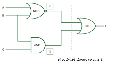
2. For the logic circuits below produce the truth tables. Rember, if there are 2 inputs then there will be 4 outputs; if there are 3 inputs then there will be 8 possible outputs. Use the idea shown in the logic circuits discussed in section 10.6.


Information transmission in a communication system
The signals from information source are added to the carrier in the modulator. The modulated signal is sent along a channel in the propagating medium by a transmitter. The propagation medium is a channel through which information is transmitted. This may be a cable or a free space.
Communication Terms and Concepts
• Communication
• Communicator
• Message
• Medium
• Noise
• Environment
• Feedback
• Levels Elements of communication
• Sender
• Receiver
• Message
• Channel
• Feedback
Types of information and requirements
• Constructional/creative information
• Operational information
• Communicational information
Simplex transmission
Simplex transmission is a single one-way base band transmission. Simplex channels are not often used because it is not possible to send back error or control signals to the transmit end.
Half-duplex communications
Half-duplex transmission is an improvement over simplex because the traffic can travel in both directions. Full-duplex networking technology increases performance because data can be sent and received at the same time.
Bandwidth and signal Frequency
The bandwidth of a composite signal is the difference between the highest and the lowest frequencies contained in that signal.
Mathematically, the bandwidth is given by;
BW = fUSB – fLSB
Where FUSB and fLSB stand for upper side band and lower side band respectively.
• Medium
• Noise
• Environment
• Feedback
• Levels
Elements of communication
Analogue signal system
Analogue systems operate with values that vary continuously and have no abrupt transitions between levels.
Analog signals
Analog signal is a continuous signal that contains time varying quantities. An analog signal is a continuous wave denoted by a sine wave and may vary in signal strength (amplitude) or frequency (time).
Digital signals
Unlike analog technology which uses continuous signals, digital technology encodes the information into discrete signal states. Numerous and very successful applications of digital technology include the continuously growing number of PC’s, the communication net work ISDN as well as the increasing use of digital control stations (Direct Digital Control: DDC).
Advantages of digital technology
• More capacity from the same number of frequencies.
• Consistent voice clarity at low received signal levels near the edge of coverage.
• Data is defined in the standard.
• Secure transmissions.
Logic gates
There are three basic logic gates each of which performs a basic logic function, they are called NOT, AND and OR. All other logic functions can ultimately be derived from combinations of these three.
UNIT 11:MOBILE PHONE AND RADIO COMMUNICATION
UNIT 11:MOBILE PHONE AND RADIO COMMUNICATION
Topic Area: DIGITAL TECHNOLOGY
Sub-Topic Area: Analog and Digital SignalsKey unit competence: By the end of the unit I should be able to distinguish mobile phone system from radio system of communication.
Unit Objectives:
By the end of this unit learners will be able to;
◊ explain the concept and principles of cellular radio network.
◊ explain the need for cellular system in modern mobile communication.

11.0 INTRODUCTION
The communication is the way of expressing our thoughts. In other words, communication means sending or receiving message from one end to other. We can express our feelings to others by speaking, writing or silent indications. All living beings communicate to each other in different ways. They have different types of voices and they understand meaning of voice of their species. Human has also developed his dialect to communicate with others. We learn different languages to understand meaning of other’s dialects.
Devices used to talk, or to send message one end to other, or from one person to other are called means of communication. Means of Communication are the most necessary part of modern lifestyle. In modern age, there are many types of means of communications like newspaper, Telephone, Mobile, TV, Internet etc. They play very important role in our daily life activities.
This concept is closely related to the concepts of blood circulation (in Biology and Medicine), transport networks, transmission of information etc.11.1 CONCEPTS OF TRANSMISSION SYSTEM
In telecommunication, a communication system is a collection of individual communication networks, transmission systems, relay stations tributary stations and Data Terminal Equipment (DTE) usually capable of interconnection and interoperation to form an integrated whole.

In the transmission section, first of all, the source generated information is fed to the input transducer, which converts energy of one form to another form, usually in electrical form. This electrical signal or base band signal is sent to the transmitter.
Transmitter:
Transmitter modifies the information signal for efficient transmission. It modulates the information signal with a high frequency carrier. After processing the signal transmitter transmits the signal, through channel to the receiver.
Channel:
Channel, media or path implies the medium through which the message travels from the transmitter to the receiver. A channel acts partly as a filter to attenuate the signal and distorts its waveform. The signal attenuation increases with the length of the channel. There are different types of channels for different communication systems, such as wire, coaxial cable, wave-guide, optical fiber or radio link through which transmitter output is sent.
Receiver:
Receiver reprocesses the signal received from the channel by undoing the signal modifications made at the transmitter and the channel. The receiver output is fed to the output transducer, which converts the electrical signal to its original form. By this way, the signal reached to its destination, to which the message is communicated.
Digital communication:
Digital communication system exchange (both transmit and receive) information to /from digital sources.
A digital (information) source produces a finite set of possible messages. Typewriter is a good example of a digital source. There is a finite no. of characters thatcan be emitted by this source.Analog communication:
Analog communication system exchange (both transmit and receive) information to /from analog sources. A microphone is a good example of an analog source. An analog information source produces messages that are defined on a continuum.
Why do we use digital not analog?
Digital communication has a number of advantages:
• Relatively inexpensive digital circuits may be used.
• Digital systems are relatively easy to design and can be fabricated on IC chips.
• Information storage is easy.
•
Operation can be programmable to update with newly upcoming technologies.
•
Privacy is preserved by using data encryption.
•
Greater dynamic range is possible.
•
Data from voice, video and data sources may be merged and transmitted over a common digital transmission system. i.e. it is easy to multiplex several digital signals.
•
In long distance communication system, noise does not accumulate from repeater to repeater.
•
Error detection and correction schemes can be employed by using coding techniques.Limitations of Digital communication system
•
Generally, more bandwidth is required than that for analog system.
•
Synchronization is required, which calls for more sophisticated device and costs more.A/D converter
We use analog to digital converter, to convert analog signals to digital signals.
A/D conversion has three steps:(a) Sampling
In this process, Continuous-time signal is converted to Discrete-time signal obtained by taking samples of the continuous-time signal at discrete-time instants.
(b) Quantization
In this process, a Discrete-time Continuous- valued signal is converted into a Discrete-time Discrete-valued (digital) signal. The sampled signal is rounding off to the fourth nearest value which is permitted for transmission by the system. The process of rounding off is called Quantization, while the possible levels permitted for transmission are called Quantizing levels.
(c) Coding
In the coding process, each discrete value is represented by 8-bit binary sequence e.g. 10010101. It consists of combinations of 0 and 1.
11.2 PRINCIPLE OF CELLULAR RADIO
The cellular concept was a major breakthrough in solving the problem of spectral congestion and user capacity. It offered very high capacity output in a limited spectrum allocation without any major technological changes. The cellular concept is a system-level idea which calls for replacing a single,
high power transmitter (large cell) with many low power transmitters (small cells), each providing coverage to only a small portion of the service area. Each base station is allocated a portion of the total number of channels available to the entire system, and nearby base stations are assigned different groups of channels so that all the available channels are assigned a relatively small number of neighbouring base stations. Neighbouring base stations are assigned different groups of channels so that the interference
between base stations (and the mobile users under their control) is minimized.By systematically spacing base stations and their channel groups throughout a market, the available channels are distributed throughout the geographic region and may be reused as many times as necessary so long as the interference between co-channel stations is kept below acceptable levels.
11.3 STRUCTURE OF CELLULAR NETWORK
An overall cellular network contains a number of different elements from the base transceiver station (BTS) itself with its antenna back through a base station controller (BSC), and a mobile switching centre (MSC) to the location registers (HLR and VLR) and the link to the public switched telephone network (PSTN).
Of the units within the cellular network, the BTS provides the direct communication with the mobile phones. There may be a small number of base stations linked to a base station controller. This unit acts as a small centre to route calls to the required base station, and it also makes some decisions about which base station is the best suited for a particular call. The links between the BTS and the BSC may use either land lines of even microwave links. Often the BTS antenna towers also support a small
microwave dish antenna used for the link to the BSC. The BSC is often co-located with a BTS.The BSC interfaces with the mobile switching centre. This makes more widespread choices about the routing of calls and interfaces to the land line based PSTN as well as the location registers.

11.4 PRINCIPLE OF CELLULAR NETWORK
Increase in demand and the poor quality of existing service led mobile service providers to research ways to improve the quality of service and to support more users in their systems. Because the amount of frequency spectrum available for mobile cellular use was limited, efficient use of the required frequencies was needed for mobile cellular coverage. In modern cellular telephony, rural and urban regions are divided into areas according to specific provisioning guidelines.
Deployment parameters, such as amount of cell-splitting and cell sizes, are determined by engineers experienced in cellular system architecture. Provisioning for each region is planned according to an engineering plan that includes cells, clusters, frequency reuse, and handovers.
Cells
A cell is the basic geographic unit of a cellular system. The term cellular comes from the honeycomb shape of the areas into which a coverage region is divided. Cells are base stations transmitting over small geographic areas that are represented as hexagons. Each cell size varies depending on the landscape. Because of constraints imposed by natural terrain and man-made structures, the true shape of cells is not a perfect hexagon
Clusters
A cluster is a group of cells. No channels are reused within a cluster. Fig.11-2 illustrates a seven-cell cluster. In clustering, all the available frequencies are used once and only once. As shown on Fig.11-3, each cell has a base station and any mobile user moving remains connected due to hand-offs between the stations.

Frequency Reuse
Because only a small number of radio channel frequencies were available for mobile systems, engineers had to find a way to reuse radio channels in order to carry more than one conversation at a time. The solution was called frequency planning or frequency reuse. Frequency reuse was implemented
by restructuring the mobile telephone system architecture into the cellular concept.The concept of frequency reuse is based on assigning to each cell a group of radio channels used within a small geographic area. Cells are assigned a group of channels that is completely different from neighbouring cells. The coverage area of cells are called the footprint. This footprint is limited by a
boundary so that the same group of channels can be used in different cells that are far enough away from each other so that their frequencies do not interfere.
Cells with the same number have the same set of frequencies. Here, because the number of available frequencies is 7, the frequency reuse factor is 1/7. That is, each cell is using 1/7 of available cellular channels.
Cell Splitting
Unfortunately, economic considerations made the concept of creating full systems with many small areas impractical. To overcome this difficulty,

system operators developed the idea of cell splitting. As a service area becomes full of users, this approach is used to split a single area into smaller ones. In this way, urban centers can be split into as many areas as necessary in order to provide acceptable service levels in heavy-traffic regions, while larger, less expensive cells can be used to cover remote rural regions.
Handoff
The final obstacle in the development of the cellular network involved the problem created when a mobile subscriber travelled from one cell to another during a call. As adjacent areas do not use the same radio channels, a call must either be dropped or transferred from one radio channel to another
when a user crosses the line between adjacent cells. Because dropping the call is unacceptable, the process of handoff was created. Handoff occurs when the mobile telephone network automatically transfers a call from radio channel to radio channel as a mobile crosses adjacent cells.
During a call, two parties are on one voice channel. When the mobile unit moves out of the coverage area of a given cell site, the reception becomes weak. At this point, the cell site in use requests a handoff. The system
switches the call to a stronger-frequency channel in a new site without interrupting the call or alerting the user. The call continues as long as the user is talking, and the user does not notice the handoff at all.
11.5 MOBILE COMMUNICATION SYSTEMS
Mobile communication systems have become one of the hottest areas in the field of telecommunications and it is predicted that within the next decade, a considerable number of connections will become partially or completely wireless. Rapid development of the Internet with its new services and applications has created fresh challenges for the further development of mobile communication systems.
We can say that mobile communication system is a high capacity communication system arranged to establish and maintain continuity of communication paths to mobile stations passing from the coverage of one radio transmitter into the coverage of another radio transmitter. A control center determines mobile station locations and enables a switching center to control dual access trunk circuitry to transfer an existing mobile station communication path from a formerly occupied cell to a new cell location. The switching center subsequently enables the dual access trunk to release the call connection to the formerly occupied cell.
ACTIVITY 11-1: The Concept of Communication
Aim: this activity aim at understanding the concept of communication.
a) The figure below shows the Amahoro village. Explain all the possible ways of communication according to the infrastructure shown.

b) Use the equipment below and create 2 communication stories. You must use at least 4 equipments.

11.6 RADIO TRANSMISSION (AM, FM, PM)
Modulation is a technique used for encoding information into a RF channel. Typically the process of modulation combines an information signal with a carrier signal to create a new composite signal that can be transmitted over a wireless link. In theory, a message signal can be directly sent into space to a receiver by simply powering an antenna with the message signal. However, message signals typically don’t have a high enough bandwidth to make efficient direct propagation. In order to efficiently transmit data, the lower frequency data must be modulated onto a higher frequency wave.
The high frequency wave acts as a carrier that transmits the data through space to the receiver where the composite wave is demodulated and the data is recovered. There are a few general types of modulation; Frequency Modulation (FM), Phase Modulation (PM) and Amplitude modulation (AM).
Frequency modulation (FM)
This is a kind of modulation which is used in every high broadcasts. The frequency of the carrier is altered at a rate equal to the frequency of the audio frequency but the amplitude remains constant.

Frequency modulation is widely used for FM radio broadcasting. It is also used in telemetry, radar, seismic prospecting monitoring newborns (for seizures via Electroencephalography), two-way radio systems, music synthesis, magnetic tape-recording systems and some video-transmission systems. In radio transmission, an advantage of frequency modulation is that it has a larger signal-to-noise ratio and therefore rejects radio frequency interference better than an equal power amplitude modulation (AM) signal. For this reason, most music is broadcast over FM radio.
Amplitude modulation (AM)
In amplitude modulation, the information signal is used to vary the amplitude of the carrier so that it follows the wave shape of information signal. Here, before the information is transmitted, it is first mixed to a carrier signal so that it can be transmitted over a long distance with low attenuation.

The modulated signal contains other frequencies called side frequencies which are created on either sides of the carrier. If the carrier frequency is fc and modulated frequency is fm, two new frequencies are fc – fm and fc + fm.

Phase modulation (PM)
Phase modulation is a form of modulation that encodes information as variations in the instantaneous phase of the carrier wave. It is widely used for transmitting radio waves and is an integral part of many digital transmission coding schemes that underlie a wide range of technologies
like WiFi, GSM and satellite television. In this type of modulation, the amplitude and frequency of the carrier signal remains unchanged after PM. The modulating signal is mapped to the carrier signal in the form of variations in the instantaneous phase of the carrier signal.Phase modulation is closely related to frequency modulation and is often used as intermediate step to achieve FM.

11.7 POST, TELEGRAPH AND TELEPHONE (PTT)
A postal, telegraph and telephone service (or PTT) is a government agency responsible for postal mail, telegraph and telephone services. Such monopolies existed in many countries, though not in North America or Japan. Many PTTs have been partially or completely privatized in recent years. In some of those privatizations, the PTT was renamed completely, whereas in others, the name of the privatized corporation has been only slightly modified.
Postal services transport mail and small packages to destinations around the world, and they are mostly public corporations. However, there has been increased privatization of postal operators in the past 20 years, and government restrictions on private postal services have eased. Postal authorities are often also involved in telecommunications, logistics, financial services and other business areas.
Rwanda is part of the Universal Postal Union, which recommends a maximum of 9,000 people per one post office branch. The ‘iPosita Rwanda’ is the company responsible for postal service in Rwanda.
A telegraph is a communication system in which information is transmitted over a wire through a series of electrical current pulses, usually in the form of Morse code. The basic components include a source of direct current, a length of wire or cable, and a current-indicating device such as a relay, buzzer or light bulb.
Telephony is the technology associated with the electronic transmission of voice, fax, or other information between distant parties using systems historically associated with the telephone, a handheld device containing both a speaker or transmitter and a receiver. With the arrival of computers and the transmission of digital information over telephone systems and the use of radio to transmit telephone signals, the distinction between telephony and telecommunication has become difficult.
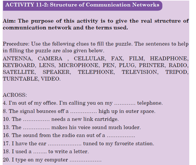


END OF UNIT QUESTIONS
1. What is amplitude modulation?
2. What is modulation?
3. What are the different types of analog modulation?
4. What is the need for modulation?
5. What are the objectives met by modulation?
6. What is frequency modulation?
UNIT SUMMARY
Concepts of transmission system
In telecommunication, a communication system is a collection of individual communication networks, transmission systems, relay stations, tributary stations, and data terminal equipment (DTE) usually capable of interconnection and interoperation to form an integrated whole.
Principle of cellular radio
The cellular concept is a major breakthrough in solving the problem of spectral congestion and user capacity. It involves dividing the area into small parts called cells. The neighbouring base stations are assigned different groups of channels so that the interference between base stations
(and the mobile users under their control) is minimized. It offers very high capacity in a limited spectrum allocation without any major technological changes.Structure of cellular network
An overall cellular network contains a number of different elements from the base transceiver station (BTS) itself with its antenna back through a base station controller (BSC) and a mobile switching centre (MSC) to the location registers (HLR and VLR) and the link to the public switched
telephone network (PSTN).The BSC is often co-located with a BTS. The BSC interfaces with the mobile switching centre. This makes more widespread choices about the routing of calls and interfaces to the land line based PSTN as well as the HLR and VLR.
Principle of cellular network
Because the amount of frequency spectrum available for mobile cellular use was limited, efficient use of the required frequencies was needed for mobile cellular coverage. In modern cellular telephony, rural and urban regions are divided into areas according to specific provisioning guidelines.
Modulation techniques
Modulation is a technique used for encoding information into a RF channel.
There are a few general types of modulation; Frequency Modulation (FM), Phase Modulation (PM), and Amplitude modulation (AM).UNIT 12:RELATIVITY CONCEPTS AND POSTULATES OF SPECIAL RELATIVITY
UNIT 12:RELATIVITY CONCEPTS AND POSTULATES OF SPECIAL RELATIVITY
Topic Area: Relativity and Particle Physics
Sub-Topic Area: Concepts and Postulates of Special RelativityKey unit competence: By the end of the unit, I be able to analyse Relativity Concepts and postulates of special relativity.
Unit Objectives:
By the end of this unit learners will be able to;◊ Explain the concept of general and special relativity.
◊ Explain the concept of the frames of reference and apply it in other theories.
12.0 INTRODUCTION
The general theory of relativity developed in the early 20th century, originally attempted to account for certain anomalies in the concept of relative motion. But it has developed into one of the most important basic concepts in physical science. The theory of relativity, developed primarily by German American physicist Albert Einstein, is the basis for later demonstration by physicists of the essential unity of matter and energy of space and time of gravity and acceleration.
12.1 DEFINITION OF RELATIVITY
This is a theory developed by Albert Einstein which says that anything except light moving with respect to the time and space depends on the position and movement of the observer. Einstein’s special theory of relativity (special relativity) is all about what’s relative and what’s absolute about time, space and motion.
The theory states that the laws of motion are the same for all inertial (non‑accelerating) frames of reference and that the speed of light (in a vacuum) is the same for all inertial reference frames. This leads to the equivalence of mass and energy, time dilation, and length contraction.
Special relativity requires us to think of space and time as inextricably linked. All our measurements of distance and time depend on the motion of the observer. The effects of time dilation and length contraction are only observed at very high speeds (close to the speed of light).12.2 CONCEPT OF SPACE, TIME AND MASS
Time Dilation
Time dilation is the phenomenon where two objects, moving with respect to each other (or even just a different intensity of gravitational field from each other) experience different rates of time flow.
Time dilation becomes most apparent when one of the objects is moving at nearly the speed of light, but it manifests at even slower speeds. Here are just a few ways we know time dilation actually takes place:
•
Clocks in airplanes click at different rates from clocks on the ground.
•
Putting a clock on a mountain (thus elevating it, but keeping it stationary relative to the ground-based clock) results in slightly different rates.
•
The Global Positioning System (GPS) has to adjust for time dilation. Ground-based devices have to communicate with satellites. To work, they have to be programmed to compensate for the time differences based on their speeds and gravitational influences.
Let’s construct a light beam clock. It consists of two mirrors, one at a distance D above the other. At t = 0, we launch a photon of light upwards from the bottom of the mirror. It reflects from the top mirror and returns to its starting position, use c as the speed of the photon;First, the photon is released. When the photon hits the top mirror, the whole clock has moved a distance L to the right. Thus, the photon travelled a longer distance
 as seen by this other observer. When it returns to the bottom mirror, it has travelled a distance
  still at speed c (recall all observers measure this same speed). Thus, Dt (the time for 1 tick according to the new observer)

Since nothing can travel faster than light, therefore, γ ≥ 1 and it appears to the observer who watches the clock go by at velocity v that it takes longer to tick
(Dt > Dt0) or runs slowly compared to his own clock. This is called time dilation and is a property of time, not just our unusual clock.EXAMPLE 12.1
An astronaut travels to a distant planet with a speed of 0.5c. According to his clock, the trip takes one year.
(a) How long does the trip appear to take to an observer on the earth?
(b) How fast should the astronaut travel so that the travel time appears two years to the observer on the earth?
Solutions
(a) The time measured in the spacecraft is the proper time since the clocks in the spacecraft are at rest with respect to the astronaut. So,

Length Contraction
If we turn our light beam clock to face in the direction of motion, time dilation implies length contraction. If the observer at rest with respect to the clock (now a ruler) says it has proper length L0, then an observer on the earth watching him and his clock/ruler by velocity v sees the ruler having length L. Objects look shorter (they are contracted) in the direction of motion.
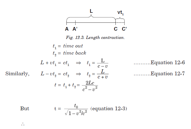
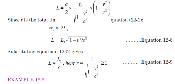
A metre stick zips by you with a speed of 0.9c. The length of the stick is along its direction of motion. How long does it appear to be?
Solution:
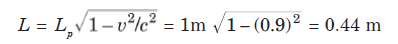
Momentum, Mass and Energy
Einstein found that momentum;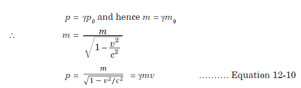
EXAMPLE 12.3
A proton travels at a speed of 0.9c. Compare its relativistic and classical momenta.
Solutions:
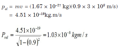
As v → c, m → ∞. Thus, infinite energy would be needed to accelerate an object to the speed of light. Einstein showed the total energy of a free body;

where m0c2 is the mass energy of the body.
As space and time are united in the theory, so are momentum and energy. We see here m0 is rest mass, p is momentum and c is speed of light.
EXAMPLE 12.4
An electron has a speed of 0.8c. What is its kinetic energy?
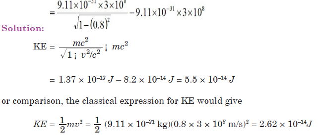
EXERCISE 12.1
1. An electron has a speed of 0.1c. What is its kinetic energy?
2. Calculate the rest mass energy of the electron in electron volts.
3. Find the kinetic energy released in the fusion reaction given below:
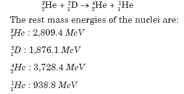
12.3 CONCEPT OF FRAME OF REFERENCE
Imagine you threw and caught a ball while you were on a train moving at a constant velocity past a station. To you, the ball appears to simply travel vertically up and then down under the influence of gravity. However, to an observer stood on the station platform, the ball would appear to travel in a parabola, with a constant horizontal component of velocity equal to the velocity of the train. This is illustrated in Fig.12-4 below.

The different observations occur because the two observers are in different frames of reference.
A frame of reference is a set of coordinates that can be used to determine positions and velocities of objects in that frame; different frames of reference move with respect to one another.
This means that when you are standing on the ground, that is your frame of reference. Anything that you see, watch or measure will be compared to the reference point of the ground. If a person is standing in the back of a moving truck, the truck is now the frame of reference and everything will be measured compared to it.
Types of Frame of Reference
There are two types of frames of reference.
Inertial Frame of Reference: It is a frame of reference in which a body remains at rest or moves with constant linear velocity unless acted upon by forces. Any frame of reference that moves with constant velocity with respect to an inertial system is itself an inertial system. In other words, it is the frame of reference in which Newton’s first law of motion holds good.
Non-inertial Frame of Reference: This is a frame of reference that is undergoing acceleration with respect to an inertial frame. An accelerometer at rest in a non-inertial frame will in general detect a non-zero acceleration. In this frame of reference, Newton’s first law of motion does not hold good.
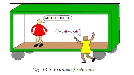
12.4 GALILEAN EQUATION OF TRANSFORMATION
Galilean transformations, also called Newtonian transformations, are set of equations in classical physics that relate the space and time coordinates of two systems moving at a constant velocity with respect to each other. Galilean transformations formally express the ideas that space and time are absolute; that length, time, and mass are independent of the relative motion of the observer; and that the speed of light depends upon the relative motion of the observer.
Let there be two inertial frames of references S and S′ where S is the stationary frame of reference and S′ is the moving frame of reference. At time t = t′ = 0, i.e., in the start, they are at the same position, i.e., observers O and O′ coincide. After that S′ frame starts moving with a uniform velocity v along x axis.
Let an event happen at position A in
the frame S′. The coordinate of the P will be x′ according to O′, the observer in S′ and it will be x according to O in S. The frame S′ has moved a distance vt in time t.
The Galilean transformation relates the coordinates of events as measured in both frames. Given the absolute nature of time, Newtonian physics, it is the same for both frames. So, this may look over-elaborate if we write t = t′
It is seen that in direction y and z, displacements remain the same. So, we may summarise these displacements as:

This set of equations is known as the Galilean Transformation. They enable us to relate a measurement in one inertial reference frame to another.
EXAMPLE 12.5
If a vehicle is moving in x-direction in system S, then what would be the velocity of the vehicle in S’?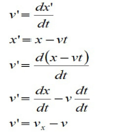 and
and
⇒

12.5 POSTULATES OF SPECIAL THEORY OF RELATIVITY
With two deceptively simple postulates and a careful consideration of how measurements are made, Einstein produced the theory of special relativity.
First postulate: The Principle of Relativity
This states that the laws of physics are the same in all inertial frames of reference.
This postulate relates to reference frames. It says that there is no preferred frame and, therefore, no absolute motion.
To understand the meaning of this postulate, consider the following situation.You are sitting in a train that is stopped at a railway station. Another train is facing the opposite direction on the track directly beside you. Ten minutes before your train is due to leave, you look out through the window at the other train and see that it is slowly starting to move relative to yours. Your first reaction would probably be one of surprise: your train was leaving.
early! After passing the train from your window, you might notice that the station was still there, and you realize that it was the other train that was moving.
Second postulate: The Principle of Invariant Light Speed
The speed of light is a constant, independent of the relative motion of the source and observer.
The speed of light in vacuum (c = 3 × 10⁸ m/s ) is so high that we do not notice a delay between the transmission and reception of electromagnetic waves under normal circumstances. The speed of light in vacuum is actually the only speed that is absolute and the same for all observers as was stated in the second postulate.
12.6 CONCEPT OF SIMULTANEITY
The concept of simultaneity says that two events that are simultaneous to one observer are not necessarily simultaneous to a second observer. Both observers are correct in their observations -- there is no best or preferred frame of reference.
If the speed of light is the same in all moving coordinate systems, this means that events that occur simultaneously in one system may not be observed as being simultaneous in another coordinate system.
An example is illustrated in the Fig. 12.7 below.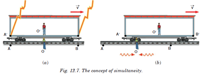
An observer O′ stands in the middle of a moving boxcar and another observer O stands at rest beside the track. When the positions of the observers coincide, a lightning bolt strikes at each end of the boxcar, leaving mass on the ground and at each end of the boxcar. The light from the lightning strikes at A and B reaches to observer O at the same time, so observer O′ concludes that the lightning strikes occurred simultaneously. But to observer O′ in the moving boxcar, the lightning strikes do not appear to occur at the same
time. The light traveling from A′ to O′ travels further than the light from B′ to O′. Because of the motion, O′ moves towards the incoming beam from B′ and away from the incoming beam from A′. So to observer O′ the strike at B′ appeared to occur before the strike at A′.
END OF UNIT QUESTIONS
1. If you were on a spaceship travelling at 0.50c away from a star, when would the starlight pass you?
2. Does time dilation mean that time actually passes more slowly in moving references frames or that it only seems to pass more slowly?
3. If you were travelling away from the Earth at 0.50c, would you notice a change in your heartbeat? Would your mass, height, or waistline change? What would observers on the earth using a telescope to see you say about you?
4. What happens to the relativistic factor when objects travel at normal everyday velocities?
5. A spaceship travels at 0.99c for 3 years ship time. How much time would pass on the earth?
6. A spaceship is travelling at a speed of 0.94c. It has gone from the earth for a total of 10 years as measured by the people of the earth. How much time will pass on the spaceship during its travel?
7. A spaceship has gone from the earth for a total time of 5 years ship time. The people on the earth have measured the time for the ship to be away to 25 years. How fast was the ship travelling?
8. A 520 m long (measured when the spaceship is stationary) spaceship passes by the earth. What length would the people on the earth say the spaceship was as it passed the earth at 0.87c?
9. A 25 m long beam is shot past a stationary space station at 0.99c. What length does the people on board the space station measure the beam to be?
10. A 100 m long steel beam is moving past the earth. Observers on the earth actually measure the steel beam to be only 50 m long. How fast was the beam travelling?
UNIT SUMMARY
Definition of relativity
Anything except light moves with respect to time and space depends on the position and movement of someone who is watching.
Concept of space, time and mass
• Time Dilation
Time dilation is the phenomenon where two objects moving relative to each other (or even just a different intensity of gravitational field from each other) experience different rates of time flow. The total time is given by
• Length Contraction
If we turn our light beam clock to face in the direction of motion, time dilation implies length contraction.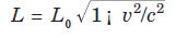
Postulates of special theory of relativity
• First postulate
This states that the laws of physics are the same in all inertial frames of reference.
This postulate relates to reference
frames. It says that there is no preferred frame and, therefore, no absolute motion.• Second postulate
This states
that speed of light, c is a constant, independent of the relative motion of the source and observer.UNIT13: INTERFERENCE OF LIGHT WAVES
UNIT13: INTERFERENCE OF LIGHT WAVES
Topic Area: ELECTROMAGNETIC WAVES
Sub-Topic Area: EM WAVES AND INTERFERENCE OF LIGHT
Key unit competence:By the end of the unit I should be able to perform experiment for interference of light waves.
Unit Objectives: By the end of this unit learners will be able to;
◊explain the concept of wave interferences and their applications in our daily life.
◊explain the interaction of electromagnetic radiations with the earth.

13.0. INTRODUCTION
Sun is a nuclear fireball spewing energy in all directions. The light that we see it simply one part of the energy that the Sun makes that our eyes can detect. When light travels between two places (from the Sun to the Earth or from a flashlight to the sidewalk in front of you on a dark night), energy makes a journey between those two points. The energy travels in the form of waves (similar to the waves on the sea but about 100 million times smaller)—a vibrating pattern of electricity and magnetism that we call electromagnetic energy. If our eyes could see electricity and magnetism, we might see each ray of light as a wave of electricity vibrating in one direction and a wave of magnetism vibrating at right angles to it. These two waves would travel in phase and at the speed of light.
13.1. NATURE OF ELECTROMAGNETIC WAVES
Electromagnetic waves are transverse waves that transfer electrical and magnetic energy. An electromagnetic wave consists of vibrating electric and magnetic fields that move through space at the speed of light. In other words electromagnetic waves have electric and magnetic fields varying perpendicularly as shown on Fig.13.1.
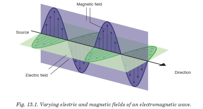
13.1.1 Producing electromagnetic waves
Electromagnetic waves are produced by charged particles and every charged particle has an electric field surrounding it. The electric field produces electric forces that can push or pull on other particles.When a charged particle moves, it produces a magnetic field which exerts magnetic forces that act on certain materials.When this charged particle changes its motion, its magnetic field changes and causes the electric field to change. When one field vibrates, so does the other and the two fields constantly cause each other to change and this produces an Electromagnetic wave.Many properties of electromagnetic waves can be explained by a wave model and some other properties are best explained by a particle model. Both a wave model and a particle model are needed to explain all of the properties of electromagnetic waves and in particular light.
13.1.2 Electromagnetic Radiation
Water waves transmit energy through space by the periodic oscillation of matter (the water). In contrast, energy that is transmitted, or radiated, through space in the form of periodic oscillations of electric and magnetic fields is known as electromagnetic radiation. In a vacuum, all forms of electromagnetic radiation—whether microwaves, visible light, or gamma rays—travel at the speed of light (c), this is about a million times faster than the speed of sound.All forms of electromagnetic radiation consist of mutually perpendicular oscillating electric and magnetic fields. Because the electromagnetic radiations have same speed (c), they differ only in their wavelength and frequency.
13.1.3 Electromagnetic spectrum
When you tune your radio, watch TV, send a text message, or pop popcorn in a microwave oven, you are using electromagnetic energy. You depend on this energy every hour of every day. Without it, the world you know would not exist.Electromagnetic energy travels in waves and spans a broad spectrum from very long radio waves to very short gamma rays. The human eye can only detect only a small portion of this spectrum called visible light. A radio detects a different portion of the spectrum, and an x-ray machine uses yet another portion.

Generation, properties and uses of those waves are summarized in the table below:


ACTIVITY 13-1: Spectrum of Electromagnetic Waves
Aim: In this activity, you will investigate the spectrum of visible light
Materials needed: a white sheet of paper, a glass prism and colored pencils
Shine a light through a prism so that the light leaving the prism falls on an unlined piece of paper. What colours do you see?
As you hold the prism and light steady, your partner will use coloured pencils to draw the colours on the piece of paper. Switch places with your partner. Again, trace the colours you see onto the piece of paper.
◊ What colours do you see on the paper? What is the order of the colours?
◊ Is it difficult to see where one colour ends and the next begins?
◊ Did the order of the colours on the paper ever change?
◊The term spectrummeans a range.
How do you think this term is related to what you observed?
13.1.4 Radiation Interaction with the Earth
Radiation that is not absorbed or scattered in the atmosphere can reach the earth and interact with its surface. There are three forms of interaction that can take place when energy strikes, or is incident upon the surface. These are: absorption (A); transmission (T); and reflection (R).
Reflection: Reflected light is perceived by our eye as colour, e.g. chlorophyll in plants reflects green light. All colours of the visible spectrum are absorbed.
Absorption: The incident energy might not get reflected or transmitted but is transformed into another form, such as heat or absorbed by chlorophyll in the process of photosynthesis.
Transmission: When energy propagates through a medium, what is not absorbed or reflected, will be transmitted through. For instance, an ultraviolet filter on a camera absorbs UV rays but allows the remaining energy to expose the film. Changes in density can also slow the velocity of light resulting in refraction such as dispersion through a prism.
13.1.5 Radiation Interaction with the Atmosphere
The Earth’s atmosphere acts as a filter to remove radiations such as cosmic rays, gamma rays, X-rays, UV rays, and large portions of the electromagnetic spectrum through the process of absorption and scattering by gases, watervapour, and particulate matter (dust).
Scattering occurs when particles or large gas molecules present in the atmosphere cause the electromagnetic radiation to be redirected from its original path. There are three types of scattering which take place: Rayleigh Scattering, Mie Scattering, Non-selective Scatter.
Rayleigh scattering refers to the scattering of light off by the molecules of air. It can be extended to scattering from particles of sizes up to about one-tenth of the wavelength of the light. It is Rayleigh scattering of white light by the molecules of the air which gives us the blue sky.

Mie scattering is caused by pollen, dust, smoke, water droplets and other particles in the lower portion of the atmosphere. It occurs when the particles causing the scattering are larger than the wavelengths of radiation in contact with them. Mie scattering is responsible for the white appearance of the clouds, as seen below.

Non-Selective Scattering occurs when the particles are much larger than the wavelength of the radiation. Water droplets and large dust particles can cause this type of scattering and cause fog and clouds to appear white to our eyes because blue, green, and red light are all scattered in approximately equal quantities (blue+green+red light = white light).
13.1.6 Atmospheric Absorption of electromagnetic waves
In addition to the scattering of EM radiation, the atmosphere also absorbs electromagnetic radiation. The three main constituents of atmosphere which absorb parts of solar radiation are Ozone, Carbon dioxide, and Water Vapour.
Ozone serves to absorb the harmful ultraviolet radiations from the sun. Without this protective layer in the atmosphere, our skin would burn when exposed to sunlight. Ultraviolet rays can also cause skin cancer to people.

Carbon Dioxide absorbs the far infrared portion of the spectrum which is related to thermal heating and results in a ‘greenhouse’ effect.
Water Vapour absorbs energy depending upon its location and concentration, and forms a primary component of the Earth’s climatic system.
13.2. CONDITIONS FOR INTERFERENCE WITH TWO SOURCES OF LIGHT
When two waves of exactly same frequency (coming from two coherent sources) travel in a medium, in the same direction simultaneously then due to their superposition, at some points intensity of light is maximum while at some other points intensity is minimum. This phenomenon is called Interference of light.
There are two types of interference: constructive interference and destructive interference.
A constructive interference is produced at a point when the amplitude of the resultant wave is greater than that of any individual wave
A destructive interference is produced at a point when the amplitude of the resultant wave is smaller than that of any individual wave.
Conditions for interference
When waves come together they can interfere constructively or destructively. To set up a stable and clear interference pattern, two conditions must be met:
• The sources of the waves must be coherent, which means they emit identical waves with a constant phase difference.
• The waves should be monochromatic - they should be of a single wavelength.
13.3. PRINCIPLE OF SUPERPOSITION
The principle states that when two or more than two waves superimpose over each other at a common particle of the medium then the resultant displacement
of the particle is equal to the vector sum of the displacements (y1 and y2) produced by individual waves. i.e.
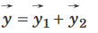
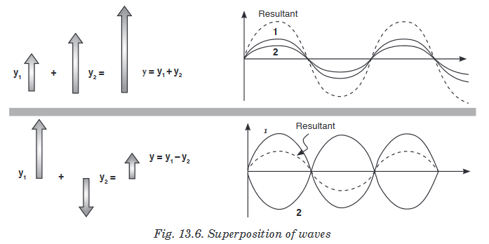
Consider two waves given as:
y1 = a1 sin wt and y2 = a2 sin (wt + f);
where a1, a2 = Individual amplitudes, f = Phase difference between the waves at an instant when they are meeting a point. I1, I2 = Intensities of individual waves
After superimposition of the given waves resultant amplitude (or the amplitude of resultant wave) is given by;

13.4. INTERFERENCE PATTERN OF TWO COHERENT POINT SOURCES OF LIGHT
The sources of light which emit continuous light waves of the same wavelength, same frequency and are in same phase (or have a constant phase difference) are called coherent sources. Two coherent sources are produced from a single source of light by using Young’s double slits.

From the Fig. 13.7. S1 and S2 are coherent sources and show interference as light passes through two slits. It also shows the appearance of the interference pattern on a screen placed in the path of the beam. You can see the maxima and minima and the way in which the intensity changes.Changing the wavelength of the light, the separation of the slits or the distance of the slits from the screen will all give changes in the separation of the maxima in the interference pattern.
13.5. YOUNG'S DOUBLE-SLIT EXPERIMENT
Monochromatic light (single wavelength) falls on two narrow slits S1 and S2 which are very close together and act as two coherent sources. When waves coming from two coherent sources superimpose on each other, an interference pattern is obtained on the screen. In Young’s double slit experiment alternate bright and dark bands are obtained on the screen.
These bands are called Fringes.

Following points must be noted and observed in the above experiment:
• Central fringe is always bright, because at central position, f = 0° or the path difference D = 0
• The fringe pattern obtained due to a slit is more bright than that due to a point.
• If the slit widths are unequal, the minima will not be completly dark. For very large slit width, uniform illumination occurs, i.e. bright and dark fringes are not formed.
• If one slit is illuminated with red light and the other slit is illuminated with blue light, no interference pattern is observed on the screen.
• If the two coherent sources consist of object and its reflected image, the central fringe is dark instead of bright one.
Calculation of fringe separation/fringe width
Consider two coherent sources (slits) S1 and S2 separated by distance d.
The distance D from the plane of slits to the screen is much greater than d.
Consider a wave from S1 that meets another wave from S2 at point P.


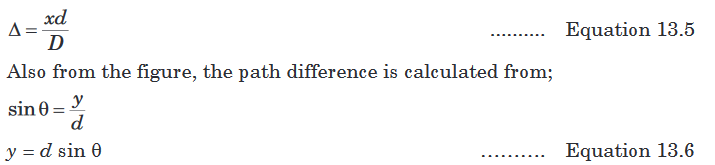
Position for the dark and bright fringes
Note that a fringe is a region of net interference. A bright fringe is obtained when the path difference is a whole number of wavelength.

Notes
• x is fringe separation and its value increases by decreasing the slit separation a.

• Increasing the width of the slits increases the intensity of waves and fringes become more blurred.
13.6. INTENSITY DISTRIBUTION OF FRINGE PATTERN
So far we have discussed the locations of only the centers of the bright and dark fringes on a distant screen. We now direct our attention to the intensity of the light at other points between the positions of maximum constructive and destructive interference. In other words, we now calculate the distribution of light intensity associated with the double-slit interference pattern.

Again, suppose that the two slits represent coherent sources of sinusoidalwaves such that the two waves from the slits have the same angular frequency w and a constant phase difference F. The total magnitude of the electric field at point P on the screen is the vector superposition of the two waves. Assuming that the two waves have the same amplitude E0, we can write the magnitude of the electric field at point P due to each wave separately as;

This result indicates that the electric field at point P has the same frequency w as the light at the slits, but that the amplitude of the field is multiplied by the factor
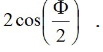
Finally, to obtain an expression for the light intensity at point P, the intensity of a wave is proportional to the square of the resultant electric field magnitude at that point;


Note that the interference pattern consists of equally spaced fringes of equal intensity. Remember, however, that this result is valid only if the slit-to-screen distance D is much greater than the slit separation d.
EXERCISE 13-1
1. In a double slit interference experiment, the distance between the two slits is 0.0005m and the screen is 2 m from the slits. Yellow light from a sodium lamp is used and it has a wavelength of 5.89 × 10⁻⁷ m. Show that the distance between the first and second fringes on the screen is 0.00233 m.
2. With two slits are spaced 0.2 mm apart, and a screen at a distance of D = 1 m, the third bright fringe is found to be displaced h = 7.5mm from the central fringe. Show that the wavelength,
 , of the light used is 5 × 10⁻⁷m.
3. Two radio towers are broadcasting on the same frequency. The signal is strong at A, and B is the first signal minimum. If d = 6.8 km, L = 11.2 km, and y = 1.73 km, what is the wavelength of the radio waves to the nearest meter?

4. Water waves of wavelength of 5.44 m are incident upon a breakwater with two narrow openings separated by a distance 247 m. To the nearest thousandth of a degree, what is angle corresponding to the first wave fringe maximum?

UNIT SUMMARY
Nature of electromagnetic waves
Electromagnetic waves are transverse waves that transfer electrical and magnetic energy. In other words electromagnetic waves have electric and magnetic fields varying perpendicularly.
Producing electromagnetic waves
Electromagnetic waves are produced by charged particles and every charged particle has an electric field surrounding it. The electric field produces electric forces that can push or pull other particles.
Electromagnetic Radiation
All forms of electromagnetic radiation consist of perpendicularly oscillating electric and magnetic fields. Various kinds of electromagnetic radiations have the same speed (c). They differ only in wavelength and frequency.
Electromagnetic energy travels in waves and spans a broad spectrum
from very long radio waves to very short gamma rays. This is called electromagnetic spectrum.From memory you should be able to list the parts in order of energy (relate how that relates to frequency and wavelength) and know how they are produced, detected and their dangers and uses - a rough idea of their approximate wavelength is also useful!
Radiation Interaction with the Earth
Radiation that is not absorbed or scattered in the atmosphere can reach and interact with the Earth’s surface. There are three forms of interaction that can take place when energy strikes, or is incident upon the surface. These are: absorption (A), transmission (T) and reflection (R).
Radiation Interaction with the Atmosphere
The Earth’s atmosphere acts as a filter to remove radiation such as cosmic rays, gamma rays, X-rays, UV rays and large portions of the electromagnetic spectrum through the process of absorption and scattering by gases, watervapour and particulate matter (dust).
Atmospheric Absorption of electromagnetic waves
In addition to the scattering of EM radiation, the atmosphere also absorbs electromagnetic radiation. The three main constituents which absorb radiation are Ozone, Carbon Dioxide and Water Vapour.
Conditions for interference to occur
• The sources of the waves must be coherent, which means they emit identical waves with a constant phase difference.
• The waves should be monochromatic - they should be of a single wavelength.
Principle of superposition
The principle states that when two or more than two waves superimpose over each other at a common particle of the medium then the resultant displacement

Double-slit experiment
Monochromatic light (single wavelength) falls on two narrow slits S1and S2 which are very close together acts as two coherent sources, when waves coming from two coherent sources superimposes on each other, an interference pattern is obtained on the screen
A bright fringe is obtained when the path difference is a whole number of wavelength.

Intensity distribution of fringe pattern
Assuming that the two waves have the same amplitude E0, we can write the magnitude of the electric field at a point let say P due to each wave separately as;

UNIT14: STELLAR DISTANCE AND RADIATION
UNIT14: STELLAR DISTANCE AND RADIATION
Topic Area: ASTROPHYSICS
Sub-Topic Area: Earth and Space
Key unit competence:By the end of the unit I should be able to analyze stellar radiation and stellar distances.
Unit Objectives: By the end of this unit learners will be able to;
◊explain the factors that affect the brightness of the star.
◊explain types of stars, their masses and use Hertzsprung-Russel diagram.
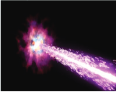
14.0 INTRODUCTION
The sun’s mass is 99.8 % of all the masses in the solar system. Because the sun is so large, its gravity is strong enough to hold all the planets and other distant objects in orbit. Unlike Earth, the sun does not have a solid surface. Like Earth, the sun has an interior and an atmosphere.
ACTIVITY 14-1: Description of Planets
Aim: the purpose of this activity is to master the planets and their descriptions.Procedures: using the sentences provided for down and cross words, fill the puzzle.

ACROSS
4. What planet resembles Neptune?
6. The Earth revolves around the ----
7. Pluto is known as a ---- planet
8. Neptune has ---- moons
9. The red planet is called ----
12. How many moons does Mercury have?
13. Uranus may have a lot of large ----
17. The Greek name for the Earth is ----
18. The hottest planet in the Solar System is ----
19. How many moons does Mars have?
20. Uranus spins on its ----
DOWN
1. What is the Earth’s moon called?
2. The ---- is the biggest of all the terrestrial planets
3. ---- has no solid surface5. Mercury has a ---- surface
6. The storm on Neptune is called the Great Dark ----
9. Jupiter has ---- moons10. Luna is covered with ----
11. Mars has the biggest ---- in the Solar System
14. ---- has many moons
15. What is another word for the hot molten substance you see after a volcano erupts?
16. Saturn has beautiful ----
17. What three letter word means Earth?
14.1. SUN’S ATMOSPHERE AND INTERIOR
14.1.1. The sun’s interior
The sun’s interior consists of the core, radiation zone and convection zone. Each layer has different properties.
Core
The core is the innermost part of the sun and takes10% of the Sun’s mass. The sun produces an enormous amount of energy in its core or central region. The sun’s energy comes from nuclear fusion. In the process of thermonuclear fusion, hydrogen in the sun join to form helium.Because of the enormous amount of gravity compression from all layers above it, the core is very hot and dense. Nuclear fusion requires extremely high temperatures and densities. The Sun’s core has a temperature of about 16 million Kelvin and has a density around 160 times the density of water. This is over 20 times denser than the dense metal iron. However, the Sun’s interior is still gaseous all the way to the very center because of the extreme temperatures. There is no molten rock in sun unlike that found in the interior of the Earth.
Radiative Zone
The radiative zone is where the energy is transported from the superhot interior to the colder outer layers by photons. Technically, this also includes the core. The radiative zone includes the inner approximately 85% of the Sun’s radius.
The light and heat produced by the sun’s core first passes through the middle layer of the sun’s interior, the radiation zone. The radiation zone is a region of very tightly packed gases where energy is transferred mainly in the form of electromagnetic radiation.
Convection Zone
The convection zone is the outermost layer of the sun’s interior. Hot gases rise from the bottom of the convection zone and gradually cool as they approach the top. Cooler gases sink, forming loops of gas that move heat towards the sun’s surface.
Energy in the outer 15% of the Sun’s radius is transported by the bulk motion of gas in a process called convection. At cooler temperatures, more ions are able to block the outward flow of photon radiation more effectively, so nature kicks in convection to help the transport of energy from the very hot interior to the cold space.
14.1.2. The sun’s atmosphere
The visible solar atmosphere consists of three regions: the photosphere, the chromosphere and the solar corona. Most of the visible (white) light comes from the photosphere, this is the part of the Sun we actually see. The chromosphere and corona also emit white light, and can be seen when the light from the photosphere is blocked out, as occurs in a solar eclipse.
The inner layer of the sun’s atmosphere is called the photosphere. Photo means “light,” so the photosphere is the sphere that gives off visible light.At the beginning and end of a solar eclipse, you can see a reddish glow around the photosphere. This glow comes from the middle layer of the sun’s atmosphere, the chromosphere. Chromo means “colour,” so the chromosphere is the “colour sphere.”During a total solar eclipse, a fainter layer called the corona is visible. The corona sends out a stream of electrically charged particles called solar wind.Features on or above the sun’s surface include sunspots, prominences and solar flares. Sunspots are areas of gas on the sun that are cooler than the gas around them. Sunspots usually occur in groups.
Reddish loops of gas called prominences link different parts of sunspot regions. Sometimes the loops in sunspot regions suddenly connect, releasing large amounts of energy. The energy heats gas on the sun to millions of degrees Celsius, causing the gas to explode into space. These explosions are known as solar flares. Solar flares can greatly increase the solar wind.
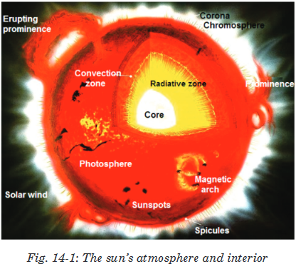
The sun’s atmosphere also consits of the planets in different positions from the sun. The inner solar system consists of the Sun, Mercury, Venus, Earth and Mars.

The planets of the outer solar system are Jupter, Saturn, Uranus, Neptune and Pluto. Since planets are very small compared to the distances between them the solar system is mostly seen as an empty space.

Theses planets are always in motion around the sun, it sometime happens that the earth, the moon and the sun are in a straight line, this is called an eclipse. The type o the eclipse that occurs when the moon passes direclty between the sun and the moon is called a solar eclipse.
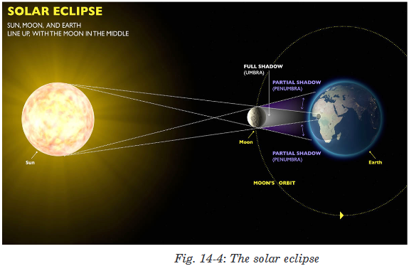
14.2. BRIGHTNESS AND MAGNITUDE SCALE OF STARS
The brightness of stars is specified with the help of a numerical magnitude system. It is assigned a number starting with the brightest star at 1 magnitude. Dimmer stars have zero or positive magnitude of brightness. The larger the number means dimmer the star is. For example, a star of 1 magnitude is brighter than a star of 0 magnitude. The decimal point is not used when star magnitudes are used on a star map.

14.3. STAR TEMPERATURE, COLOUR AND SPECTRA
Stars are dense hot balls of gases. So their spectra are similar to that of a perfect thermal radiator, which produces a smooth continuous spectrum. Therefore, the colour of stars depends on their temperature---blue stars are hotter than white stars which in turn hotter than red stars. Stars with intermediate temperature appear white to orange in colour.The surface layers of a star constitute photosphere and it emits continuous spectrum like a black body. The photosphere of the star is surrounded by relatively cooler layer called reversing layer. When the full spectrum radiation from the photosphere of the star passes through the reversing layer, the radiations of certain wavelength are selectively absorbed.
The dark lines in the spectrum correspond to the wavelengths which have been absorbed by reversing layer of the star and are characteristic of the composition of the reversing layer. Hence, by noting the position of the dark lines in the spectrum of a star, the constituents of the reversing layer of the star can be identified.
The stellar spectra have been divided into seven classes designated by letters O, B, A, F, G, K and M
• Class O spectra: It represents the hottest stars having temperature in the range from 30,000K to 40,000K. These stars are dark blue in colour and their spectra reveal ionized helium, hydrogen and calcium in their reverting layers.
• Class B spectra: The surface temperature ranges from 15,000K to 28,000K and they are bluish in colour. As their spectra contain mainly dark lines corresponding to neutral helium, they are called helium stars. They also contain ionized oxygen and nitrogen.
• Class A spectra: The surface temperature of such stars ranges from 9,500K to 11,000K. They are white in colour. The spectra of these stars show hydrogen lines predominantly. Their spectra contain lines corresponding to ionized magnesium, silicon, iron, calcium etc.
• Class F spectra: The surface temperature of stars in this class ranges from 6,500K to 7,500K. These stars appear green in colour. The spectra of these stars show a decrease in hydrogen lines and a sharp increase in the lines of ionized metals.
• Class G spectra: The surface temperature of this class is of order of 5,800K and they are yellowish in colour. The hydrogen lines further decrease and numerous metallic lines show up in spectrum. Their spectra also display lines corresponding to ionized calcium, iron and a band corresponding to carbon.
• Class K spectra: The surface temperature of the star belonging to this class is of order 4500K. These stars appear orange in colour. The spectra of stars in this class have bands due to the presence of hydrocarbons.
• Class M spectra: The surface temperature of stars in this class is about 3,500K. Such stars appear red in colour. Their spectra show absorption bands that indicate the presence of titanium oxide strongly.
14.4. TYPES OF STARS
By taking a close look into the components of sky, one will notice that there are a variety of stars up there. The following are all the different types of stars in the known universe.
Main Sequence Stars—A main sequence star is any star that has fusing hydrogen in its core and has a stable balance of outward pressure from core nuclear fusion and gravitational forces pushing inward. Our Sun is a main sequence star. A main sequence star will experience only small fluctuations in luminosity and temperature. Very massive stars will exhaust their fuel in only a few hundred million years. Smaller stars, like the Sun, will burn for several billion years during their main sequence stage. Very massive stars will become blue giants during their main sequence.
Most stars, including the sun, are “main sequence stars,” As the hydrogen fuel in thermonuclear fusion reaction, converting hydrogen into helium. For these stars, the hotter they are, the brighter they appear. These stars are in the most stable part of their existence; this stage generally lasts for about 5 billion years.
When the stars have depleted their hydrogen supply they begin to die. The core contracts as the outer layers expand. These stars will eventually explode (become a planetary nebula or supernova, depending on their mass). Later they become white dwarfs, neutron stars or black holes (again depending on their mass).
Smaller stars (like our Sun) eventually become faint white dwarfs (hot, white, dim stars) that are below the main sequence. These hot, shrinking stars have depleted their nuclear fuels and will eventually become cold, dark, black dwarfs.
Red Giants
A red giant is a large star that is reddish or orange in colour. It represents the late phase of development in a star’s life, when its supply hydrogen has been exhausted and helium is being fused. This causes the star to collapse, raising the temperature in the core. The outer surface of the star expands and cools, giving it a reddish colour. Red giants are very large, reaching sizes of over 100 times the star’s original size. Very large stars will form what are called red supergiants.
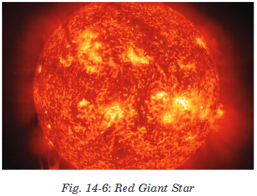
White Dwarfs
A white dwarf is an average-sized star that has passed through the red giant stage of its life. After the star has used up its remaining fuel. At this point the star may expel some of its matter into space, creating a planetary nebula. What remains is the dead core of the star. Nuclear fusion no longer takes place. The core glows because of its residual heat. Eventually the core will radiate all of its heat into space and cool down to become what is known as a black dwarf. White dwarf stars are very dense.

Brown Dwarfs
These are also known as failed stars. Just like normal stars, they are formed in the same way but they do not accumulate enough mass to generate nuclear fusion in the core hence the name failed stars. They are smaller than the normal stars.

Variable Stars
These are stars that tend to change their brightness. Unlike other stars that maintain a constant brightness, these stars tend to vary their brightness from time to time.
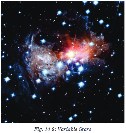
Binary Stars
This is a system of two stars that go around each other or a common centre of mass cloud. True binaries revolve around one another. A well known example of which stars is Polaris.
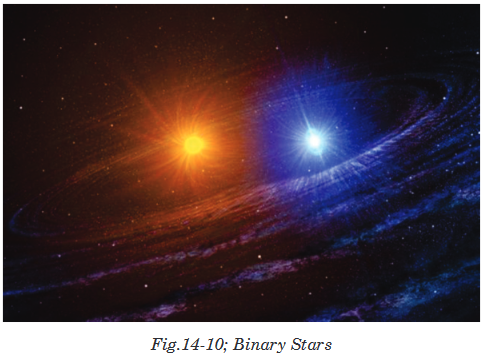
Black Holes
A black hole is a place in space where gravity pulls so much that even light can not get out. The gravity is so strong because matter has been squeezed into a tiny space. This can happen when a star is dying. While not technically stars, these are formed as a result of the massive gravity created by large stars collapsing in on themselves.

14.5. HERTZSPRUNG-RUSSEL DIAGRAM
The Hertzsprung-Russell (HR) diagram is actually a graph that illustrates the relationship that exists between the average surface temperature of stars and their absolute magnitude, which is how bright they would appear to be if they were all the same distance away.
The brightness of stars is affected by temperature and size. The brightest stars would be those that are large and hot. The least bright stars would be small and cool. The colour of a star is determined by its surface temperature, which is illustrated on the HR diagram.
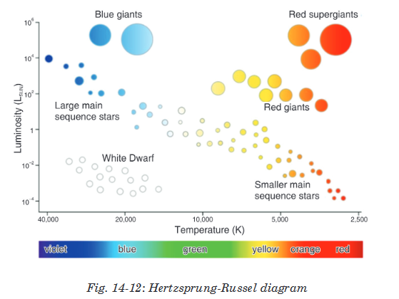
14.6. STELLAR DISTANCE AND MASSES: PARALLAX,BINARY STARS AND MASS-LUMINOSITY RELATIONSHIP
Stellar Parallax
A nearby star’s apparent movement against the background of more distant stars as the Earth revolves around the Sun is referred to as stellar parallax. The parallax can be used to measure the distance to the few stars which are close enough to the Sun to show a measurable parallax. The distance to the star is inversely proportional to the parallax. The distance to the star in parsec is given by:
 here p is the parallax angle observed, and d is the actual distance measured in parsecs. A parsec is defined as the distance at which an object has a parallax of 1 arcsecond. This distance is approximately 3.26 light years.
Stellar mass is a phrase that is used by astronomers to describe the mass of a star. After many star masses have been measured a graph can be made of the masses versus the brightness of the stars. This produces a mass-luminosity relation for Main Sequence stars - but not other luminosity classes.
The relation can be approximated by the formula:
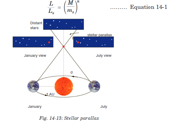
Inverse Square Law – Calculating Luminosity
A quick glance at the night sky will tell you that different stars have different brightness. But how much of that effect is due to the fact that some stars are further away, and how much is due to certain stars being intrinsically brighter?
If we know the distances from parallax, we can remove the effect of distance and calculate the intrinsic brightness, or luminosity – the total energy the star emits per second. Imagine building a gigantic shell centered around the star, giving that shell a radius d equal to the distance between the star and Earth. A detector placed on the inside of the shell receives a certain amount of energy per second – this is the brightness b we measure, in ergs per second per square centimeter. But while a single detector only receives a tiny fraction of the star’s energy, if we were to cover the entire shell in detectors, the shell would receive all the energy from the star. Since the surface area of the shell is 4pd2, and each unit of area receives b units of energy per second, the total luminosity (the energy per second captured by the whole sphere) is equal to
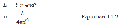
Luminosity is normally given in watts (joules per second) or ergs per second, or in solar luminosities, while the parallax formula gives d in units of parsecs. You have to convert the distance to meters or centimeters before plugging in – unless you use ratios.
Stellar Masses The most dependable method of “weighing” a star is to use Newton’s version of Kepler’s Third Law. Stellar masses can only be measured in binary star systems in which the orbital properties of the two stars have been determined.
Visual binary – a pair of stars that we can see distinctly as the stars orbit each other.
Eclipsing binary – a pair of stars that orbit in the plane of our line of sight. When neither star is eclipsed (or blocked), we see the combined light of both stars. When one star eclipses the other, the apparent brightness of the system drops. Example: Algol (the “demon” star in the constellation Perseus)
If binary system is neither visual nor eclipsing, we may be able to detect its binary nature by observing Doppler shifts in its spectral lines.
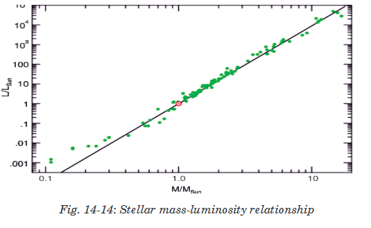
END OF UNIT QUESTIONS
1. What is a star?
2. Why does the main sequence form a line in the H-R diagram?
3. What are white dwarfs (and neutron stars) made of?
4. Which star has the lowest surface temperature?

5. Which star produces less energy per second (luminosity)? The extra luminosity is produced by more fusion reactions)

6. Which line shows the red giant planetary nebula stage on the Hertzsprung Russell Diagram? Remember that green line is actually between the red giant branch and the supergiant branch and occurs when stars start blowing off their outer layers in planetary nebulae.

7. How do black holes and neutron stars form?
8. What property of black holes can we measure with the velocity and distance of the gas orbiting the black hole? (Note : We can also use the orbital properties of companion star, if the black hole has one)
UNIT SUMMARY
Sun’s atmosphere and interior
• The sun’s interior consists of the core, radiation zone and convection zone. Each layer has different properties.
• The core is the innermost part.
• The radiative zone is where the energy is transported from the superhot interior to the colder outer layers by photons.
• The convection zone is the outermost layer of the sun’s interior.
The sun’s atmosphere
• The visible solar atmosphere consists of three regions: the photosphere, the chromosphere, and the solar corona.
Brightness and magnitude scale of stars
• The brightness of stars is specified with the magnitude system. And is assigned a number starting with the brightest star starting at about-1 magnitude.
Star temperature, colour and spectra
• Stars are dense hot balls of gas so their spectra is similar to that of a perfect thermal radiator, which produces a smooth continuous spectrum. Therefore, the colour of stars depends on their temperature---hotter stars are bluer and cooler stars are redder.
Types of stars
• Red Giants • White Dwarfs
• Brown Dwarfs • Variable Stars
• Binary Stars • Black Holes
Hertzsprung-Russel diagram
• The Hertzsprung-Russell (HR) diagram is actually a graph that illustrates the relationship that exists between the average surface temperature of stars and their absolute magnitude, which is how bright they would appear to be if they were all the same distance apart.
INDEX
Acid Rain, 183, 192
Amplitude, 10, 30, 67, 100, 105,
Analogue signal, 325, 336 Angle, 42Angular Momentum, 255, 272Angular velocity, 30, 67antinodes, 107, 108, 109, 126Astronomy, 2Atomic models, 274Belt conveyor, 168binding energy, 16, 17, 308black body, 3, 13, 18, 24, 26, Blackbody radiation, 13Bohr’s atomic model, 278, 311bomb, 180, 190Boolean expression, 332bridge, 88, 96, 154brightness, 203, 290, Bucket elevator, 170capacitance, 89capacity, 168, 170, 171, 326, 329, 336, carboniferous, 159catastrophic, 16, 182cathode, 21, 202, 203, 204, 220, 283, 284, 286, 294, 300, 308, 312, 313Cathode ray oscilloscope, 203, 283, 312Cathode ray tube, 202, 219cell, 138, 139, 140, 141, 142, 143, 144, 145, 146, 148, 149, 150, 151, 158, 299, 308, 313, centripetal force, 214, 246, 247, 265, 278, 279, 311Channels, 316, 335Chemical propulsion, 245circuit, 2, 89, 90, 128, 129, 130, 131, 132, 133, 134, 135, 136, 137, 138, 141, 143, 144, 145, 146, 147, 148, 150, 152, 153, 154, 155, 156, 157, 294, 295, 300, 313, 326, 332, 333, 334Coal, 159, 163, 165, 166, 168, 169, 174, 190Coherent, 16, 26Coil, 45communication, 125, 246, 254, 259, 261, 272, 315, 316, 317, 318, 319, 320, 323, 324, 328, 335, 336, 338, 339.complex circuits, 128, 136Compound pendulum, 53, 68Compton, 9, 16, 17, 26, 301, 302, 306, 307, 308, 313computer monitors, 203, 220Cosmic velocity, 264, 273Coulombic interactions, 16Critically damped, 77, 96crude oil, 172Damped oscillations, 71, 73damping, 72, 74, 75, 77, 78, 81, 82, 85, 95Data, 79, 143, 160, 263, 321, 329, 330, 336.Dead storage, 165, 191destructive interference, 117.Detectors, 22
Diffraction, 23, 118, 119, 121digital signals, 314displacement, 10, 29, 30, 31, 32, 37, 38, 39, 40, 41, 47, 55, 58, 59, 60, 61, 63, 64, 65, 67, 69, 74, 75, 76, 77, 78, 93, 102, 103, 104, 106, 107, 108, 109, 126.e.m.fs, 141, 142Earthquake, 111, 112Einstein, 6, 14, 19, 24, 289, 290, 292, 293, 297, 299, 313electric dipole, 200, 201, 219Electric field, 193, 194, 218electric potential, 129, 130, 134, 194, 195, 196, 197, 199, 201, 216, 217, 218, 219Electric propulsion, 245Electrodynamics, 210, 220electromagnetic radiation, 16, 18, 19, 177, 210, 287, 290, 312electromagnetism, 1electron, 2, 3, 14, 15, 16, 17, 18, 19, 20, 21, 22, 23, 24, 25, 26, 202, 203, 204, 205, 206, 207, 208, 209, 210, 211, 217, 220, 275, 277, 278, 279, 280, 281, 282, 285, 286, 287, 289, 293, 294, 295, 301, 302, 303, 304, 307, 308, 309, 310, 311, 312, 313 electron gun, 202, 286Electron Microscopes, 20energy, 2, 3, 4, 6, 8, 13, 14, 15, 16, 17, 18, 19, 21, 23, 24, 25, 26, 42, 55, 58, 59, 60, 61, 62, 69, 71, 72, 74, 85, 86, 90, 91, 98, 99, 101, 111, 112, 125, 134, 159, 160, 163, 164, 165, 174, 175, 176, 177, 179, 181,182, 185, 189, 190, 191, 194, 196, 197, 201, 202, 209, 213, 214, 215, 216, 217, 218, 219, 221, 244, 245, 256, 257, 258, 259, 266, 272, 273, 277, 278, 279, 281, 283, 287, 288, 289, 290, 291, 292, 293, 294, 295, 296, 297, 298, 299, 301, 302, 303, 304, 306, 308, 309, 310, 311, 312, 313, 339 Environment, 317, 335 equipotential, 199, 200, 201, 219 equipotential lines, 199 equipotential surface, 199, 219 Escape velocity, 213, 221ether, 7, 9explosion, 179, 180Feedback, 317, 320, 335fission, 160, 176, 177, 178, 179, 181, 191Flight conveyor, 168fluorescent, 20, 23, 203fluorescent screen, 20forced oscillation, 81, 96Fossil, 159, 163, 164, 174, 176, 190Fraunhofer diffraction, 118, 120Frequency, 10, 25, 29, 67, 105, 291, 297, 313, 324, 336Fresnel’s diffraction, 118, 119fringe separation, 384, 387, 415fuel, 159, 163, 175, 176, 190, 191, 242Full-duplex, 323, 336G-clamp, 33Geostationary, 254, 261, 272Grab bucket elevator, 171gravitational field, 211, 248 gravitational potential, 193, 211, 221Half-duplex communications, 322, 335harmonics, 63, 123Highly elliptical orbit, 260, 273homogeneous, 7, 82, 316Huygen’s Wave, 24Huygens, 7, 8, 9, 24, 66, 100, 114Huygens principle, 7Inertia, 152Information transmission, 315, 335intensity, 8, 16, 72, 204, 205, 285, 286, 288, 289, 290, 291, 292, 300, 312, 313Intensity, 100, 126, 280, 291, 313interference, 18, 63, 117, 121, 126, 317Interference, 117internal resistance, 139, 140, 142, 143, 144, 145, 146, 150Kepler’s laws, 225, 269Kinematics, 28Kirchhoff‘s laws, 130, 157Levels, 317, 335light, 1, 2, 3, 4, 6, 7, 8, 9, 10, 15, 16, 18, 19, 20, 22, 23, 24, 25, 26, 40, 42, 49, 51, 62, 65, 68, 75, 114, 115, 116, 117, 120, 121, 180, 183, 184, 188, 192, 202, 210, 220, 223, 231, 280, 285, 286, 287, 288, 290, 291, 292, 293, 294, 295, 296, 298, 299, 301,302, 308, 309, 310, 312, 313, 314, 327 Linear acceleration, 31, 68 Linear velocity, 30, 67 Logic gates, 331, 337 longitudinal, 7, 98, 101, 110, 111, 112, 113Lorentz transformations, 367Low earth orbit, 260, 273 luminiferous, 7, 9 Luminiferous, 9 mass, 6, 14, 15, 16, 24, 26, 28, 34, 39, 40, 42, 43, 45, 46, 47, 48, 49, 50, 53, 57, 58, 66, 67, 68, 73, 74, 79, 82, 94, 95, 123, 179, 187, 204, 211, 212, 213, 214, 215, 216, 221, 223, 227, 229, 230, 231, 232, 235, 237, 239, 240, 247, 250, 255, 257, 258, 259, 265, 268, 269, 272, 275, 277, 310, 311matter, 1, 3, 6, 17, 19, 24, 26, 98, 113, 132, 152, 183, 210, 242, 245, 271, 274, 291, 292Maxwell, 210mechanics, 1, 5, 24, 292 medium, 7, 8, 16, 25, 99, 101, 102, 106, 110, 113, 116, 124, 125, 126, 224, 260, 273, 314, 315, 316, 319, 335medium earth orbit, 260, 273Meltdown, 185Message, 316, 319, 335Metre rule, 33Microscopes, 20, 26Microwave ovens, 90, 96Mie scattering, 378, 379Modulation techniques, 349, 355momentum, 14, 19, 24, 26, 39, 255, 256, 272, 279, 301, 302, 303, 308monochromatic light, 6, 8, 25 Musical instruments, 88, 96Newton, 8, 14, 56, 73, 223, 225, 242, 269nodes, 107, 108, 109, 121, 126, 133Noise, 152, 317, 330, 335non fossil, 159, 165Nuclear, 176, 177, 179, 180, 181, 182, 185, 187, 191, 245, 276Ocean, 111Oil, 163, 164, 175, 191Orbits, 222, 279, 280oxygen, 164, 167, 184ozone, 160, 181, 183Ozone, 183, 192Pair Production, 17, 26 particles, 3, 4, 6, 7, 16, 17, 19, 24, 26, 101, 102, 110, 132, 168, 184, 188, 192, 200, 201, 210, 211, 215, 220, 224, 275, 276, 277, 292, 301, 303, 310, 311Peat, 165Periodic Time, 29, 67Petroleum, 164, 191Phase modulation, 351, 352phosphorescence, 287, 288, 312Phosphors, 286Photodisintegration, 18, 26photoelectric, 6, 9, 18, 19, 24, 274, 275, 276, 289, 290, 291, 292, 293, 295, 297, 298, 299, 300, 308, 309, 310, 312, 313photoelectric current, 6, 292photoelectric effect, 6, 9, 19, 274, 275, 289, 290, 291, 292, 293, 298, 299, 300, 310, 312, 313Photoelectric emission, 25, 288, 290,312photoelectrons, 6, 290, 291, 292, 300, 308photon, 3, 4, 6, 14, 15, 16, 17, 18, 19, 23, 24, 26, 279, 287, 289, 290, 292, 293, 297, 298, 301, 302, 303, 306, 307, 308, 309, 310, 312photons, 2, 6, 15, 16, 20, 23, 24, 26, 98, 287, 289, 290, 293, 301, 308physiotherapy, 2Planck’s hypothesis, 6, 18Planck’s constant, 4, 6, 292, 298, 299, 309planet, 213, 221, 226, 227, 228, 229, 231, 246, 248, 250, 251, 256, 259, 261, 264, 268, 269, 270, 272polarisation, 9, 18pollution, 160, 161, 165, 174, 175, 184, 185, 189, 190, 192postulates, 6, 278, 311, 356, 357potential difference, 25, 129, 130, 138, 147, 196, 198, 199, 200, 218, 294, 313potential energies, 2, 62potentiometer circuits, 138Power, 152, 331principle of complementarities, 18Progressive waves, 101 prominences, 397propagation number, 100, 126pulses, 6, 106Quantum mechanics, 1, 24quantum physics, 19quantum theory, 3, 6, 24, 210, 289, 310Radio, 89, 90, 114, 320 Radiography, 2Rayleigh scattering, 16 Receiver, 319, 335rectilinear propagation, 8, 9relativity, 210, 220Resistors, 136resonance, 70, 71, 86, 87, 88, 89, 90, 91, 92, 95, 96, 287Resonances, 85Rockets, 242, 271Rutherford’s atomic model, 276, 310Salinity, 185, 192Sampling, 341Satellite, 246, 247, 249, 252, 254, 255, 256, 259, 272, 273Scanning, 20, 21, 22, 26, 204Scattering, 16, 26, 277Screw conveyor, 169 Sender, 316, 318, 335Shock Absorber, 71Sign conventions, 131Simple harmonic motion, 27, 29, 30simple pendulum, 32, 40, 42, 43, 44, 53, 54, 57, 58, 66, 67, 68, 69simple potentiometer, 138, 158Simplex transmission, 321, 322, 335sinusoidal, 60, 82, 107, 324solar cells, 3solar panels, 3, 300Spacecraft Propulsion, 243, 244, 271special relativity, 15, 356, 357, 371spectrum, 3, 24, 114, 276, 278, 280, 281, 287speed, 4, 6, 7, 8, 14, 15, 16, 17, 42, 57, 62, 65, 74, 99, 105, 106, 116, 121, 125, 210, 215, 217, 220, 248, 249, 259, 266, 269, 280, 292, 297, 308, 310spring, 28, 40, 45, 46, 47, 48, 49, 50, 57, 58, 62, 65, 66, 67, 68, 73, 74, 79, 82, 94, 95stationary wave, 106Stopping potential, 25, 294, 309String, 42superposition, 63, 64, 105, 106, 117, 126, 224Surface Waves, 113Technology, 21, 330telecommunication, 339temperature, 13, 14, 160, 166, 167, 176, 180, 183, 186, 187, 192, 245, 327thermionic emission, 202, 276, 283thermodynamics, 1Thomson scattering, 17Torsion Pendulum, 51 trajectory, 207, 220transformations, 164, 181Transmission Electron Microscope, 20transmutation, 18Tuning circuit, 89, 96TV tubes, 285, 312Uranium, 177, 180, 182, 191Velocity, 58, 246, 247, 272voltage drop, 129, 130washing machine, 86, 87, 96water, 7, 10, 90, 91, 97, 98, 101, 111, 113, 160, 164, 166, 167, 170, 172, 176, 178, 181, 183, 184, 185, 186, 189, 192Physics Senior Five344345 Wave normal, 26wave number, 100, 104, 105, 126wave theory, 7, 8, 99, 302, 310Wave theory, 6, 25 wave-front, 7wavelength, 4, 5, 6, 8, 10, 16, 19, 20, 25, 26, 99, 104, 108, 121, 125, 127, 279, 281, 287, 291, 307, 308, 309, 310wavelengths, 3, 7, 99, 114, 125, 281, 308, 309, 311 wavelets, 7, 25, 100, 116Wave-particle duality, 18, 26waves, 7, 8, 10, 13, 18, 19, 26, 88, 89, 91, 97, 98, 99, 100, 101, 102, 104, 106, 107, 108, 109, 110, 111, 112, 113, 114, 115, 116, 117, 118, 119, 120, 125, 126, 127, 292, 316, 327, 330weapons, 177, 179, 180, 182, 191Work Function, 292, 297X-rays, 16, 23, 114, 308Young’s double slit, 18, 120
BIBLIOGRAPHY
1. Abott, A. (1989). Physics. Chicago: Heinman Educational Publisher.
2. David, V. F., Griffith, T., John, G. L., Jay, M., Beth, M., Steve, M., & Camille, W. (2006). Science Explorer. Mexico: Pearson Prentice hall.
3. Elizabeth, C., Donald, C., Linda, C., Lisowski, M., & Jan, J. (2006). Science Explorer. Mexico: Pearson Prentice Hall.
4. Nelkon, M., & Parker, H. (1995). Advanced Level Physics. London: Heinemann.
5. Richard, O. (2009). Physics for Rwanda Secondary School. Kigali: Fountain.
6. Tom, D. (2000). Advanced Physics. London: Hodder Education.
7. Wysession, M., Frank, D., & Yancopoulos, S. (2004). Physical Science. Boston, Massachusetts, Upper Saddle River, New Jersey: Pearson Prentice Hall.
8. Valerio Faraoni,(2003): Exercises on Environmental Physical, Springer, ISBN-10: 0-387-33912-4 ISBN-13: 978-0387-33912-2
9. Peter Hughes, N.J. Mason,(2001): Introduction to Environmental Physics: Planet Earth, Life and Climate,
10. Gerard P.A. Bot, (2010): Agricultural Physics. Publisher: Springer, ISBN: 978-3-540-74697-3, ISBN: 978-3-540-74698-0
11. Franklin Hiram King, (1904): A Text Book of the Physics of Agriculture, Publisher: Madison, Wis., ISBN: 1176279092 / ISBN-13: 9781176279094
12. Roger A. Freedman and William J. Kaufmann III, (2008): Stars and galaxies. Universe, Third Edition, W.H. Freeman and Company, New York. ISBN-13:978-0-7167-9561-2
13. Neil F. Comins, (2009): Discovering the Universe: From the stars to the Planets, W.H. Freeman and Company, New York. ISBN-13:978-1-4292-3042-1
14. STACY E. PALEN, (2002): Theory and Problems of Astronomy. Schaumâ ™s Outline Series, McGraw-HILL.
15. STAN GIBILISCO, (2003): Astronomy demystified. McGraw-HILL
16. Marc L. KUTNER,(2003): Astronomy: A Physical Perspective, Cambridge University Press, ISNB-13:978-0-511-07857-6
17. Stan Gibilisco (2010): Electronics Demystified, Second Edition. ISBN-13: 978-0071768078 ISBN-10: 0071768076
18. Advanced Physics, Tom Duncan, John Murray (2000).
19. Fundamentals of Physics, David Halliday, Robert Resnick and Jearl Walker, 7th Edition John Wily (2004).
20. Hastings, R. J., 1987, “Creation Physics” and the speed of light; Unpublished manuscript.
21. Morse, P., 1974, Thermal Physics: New York, Benjamin.
22. Tryon, E. P., 1989, Cosmic Inflation, in Meyers, R. A., ed., Encyclopedia of Astronomy and Physics: San Diego, California, Academic Press.
23. Weinberg, S., 1977, the First Three Minutes: A Modern View of the Origin of the Universe: New York, Basic Books.