General
- Physics S5 SB File Uploaded 28/01/22, 13:51
- Physics S5 TG File Uploaded 4/01/24, 11:45
Unit 5: COMPLEX ELECTRICAL CIRCUIT
Unit 5: COMPLEX ELECTRICAL CIRCUIT
Topic Area: ELECTRICITY
Sub-Topic Area: Current Electricity
Key topic competence: By the end of the unit I should be able to construct and to analyze a complex electrical circuit.
Unit Objectives:
By the end of this unit, learners should be able to:
◊ analyze complex electrical circuits well.
◊ use Kirchhoff’s laws in circuit analysis accurately
◊ analyze simple potentiometer circuits clearly.

5.0 INTRODUCTION
A complex circuit configuration is one that contains components that are connected either in parallel or in series with each other. If a circuit can be reduced to a single resistor, it is a series or parallel circuit. If not, it is a complex circuit. If the circuit is complex and is mixed with series and parallel networks of resistors and supplies, we may want to look if it is feasible to reduce these to a single power supply and a single resistor which would make them either a series or a parallel simple circuit.
Most electronic devices we use at home have built-in complex circuits to perform different tasks. Also the concept of this unit is helpful in other subjects like electrons and conductors (in Chemistry), volume adjustment circuits in radios.
Opening questions


5.1 KIRCHHOFF’S LAWS
Next to Ohm’s Law in the fundamental rules which govern the behaviour of electric circuits are Kirchhoff’s Circuit Laws. Gustav Kirchhoff in 1845 formulated two circuit laws, one of which essentially establishes the conservation of charge and the other establishes the conservation of potential.

Sign conventions
• The potential change across a resistor is – IR if the loop is traversed along the chosen direction of current (potential drops across a resistor).
• The potential change across a resistor is + IR if the loop is traversed opposite the chosen direction of current.
•If an emf source is traversed in the direction of the emf, the change in potential is positive.
• If an emf source is traversed in the opposite direction of the emf, the change in potential is negative.
5.1.1 Kirchhoff’s Current Law
Kirchhoff’s first law, known as Kirchhoff’s Current Law (KCL) or Kirchhoff’s Junction Rule, essentially expresses the conservation of charge, which can be thought of as the conservation of matter. This implies that charge cannot
appear from anything at any point in a circuit, neither can it disappear into oblivion at any point.
Kirchhoff’s Current Law states that “the algebraic sum of the currents flowing at a node or junction in an electric circuit is zero”.
This means that currents are added with respect to their directions. Let us consider the junction shown on Fig. 5.3 below.

From the figure;

Note that both forms are completely mathematically consistent.
EXAMPLE 5.1
In the circuit of Fig. 5.4, the magnitudes of the currents are as follows:


Notes: Any calculated value of current which works out to be negative simply indicates that in practice, the current is actually flowing in a direction opposite to that assigned in the schematic diagram of the circuit.
5.1.2 Kirchhoff’s Voltage Law
Kirchhoff’s second circuit law, known as Kirchhoff’s Voltage Law (KVL) or Kirchhoff’s Loop Rule, essentially formulates the conservation of energy in the form of electric potential around a circuit in which current is flowing. This means that no net voltage can be created or destroyed around the loop of a closed circuit.
Kirchhoff’s Voltage Law states that “the algebraic sum of the potentials around a closed electric circuit is zero.”
Consider an electrical network shown in Fig. 5.5 below.

EXAMPLE 5.2
In the circuit of Fig.5.5, the magnitudes of the potentials are as follows:

5.2 DESIGN OF COMPLEX AND SIMPLE ELECTRIC CIRCUITS
An electric circuit is a collection of electrical components connected by conductors. A simple electric circuit consists of a supply with either series or parallel network of resistors.

This circuit contains neither simple series nor simple parallel connections. It contains elements of both. Because the circuit is a combination of both series and parallel, we cannot apply the rules for voltage, current and resistance “across the table” to begin its analysis. This is shown below;


5.3 RESISTORS AND ELECTROMOTIVE FORCES IN SERIES AND PARALLEL COMPLEX CIRCUITS
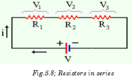
This section examines how Kirchhoff’s voltage and current laws are applied to the analysis of complex circuits. In the analysis of such series-parallel circuits, we often simplify the given circuit to enable us to clearly see how the rules and laws of circuit analysis apply. We might need to redraw circuits whenever the solution of a problem is not immediately apparent. Resistors are said to be in series if they are arranged side by side in a such way that the total potential difference is shared by all resistors and the current flowing through them is the same. This arrangement is shown below:
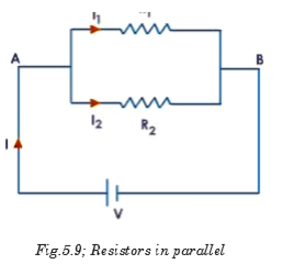
A parallel circuit is a circuit in which the resistors are arranged with their heads connected together, and their tails connected together. The current in a parallel circuit breaks up, with some flowing along each parallel branch and re-combining when the branches meet again. The voltage across each resistor in parallel is the same.
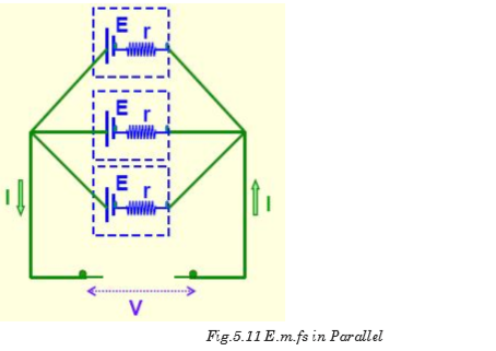
The same idea of series and parallel resistors is applied in series and parallel cells. For series e.m.fs the total e.m.f is equivalent to the sum of individual e.m.fs with respect to the direction of currents they generate.

When these cells are connected in parallel, the total e.m.f e equivalent to the e.m.f of only one cell.
To solve the resistor circuits using Kirchhoff’s rules,
1. Define the various currents
• This can be done by either defining branch (segment) currents for each element in the circuit, or defining loop currents for each loop in the circuit.
2. If using branch currents, use Kirchhoff’s Junction Rule to look for interdependent currents. This allows for reducing the number of variables being solved for.
3. Use Loop Rule to define voltage equations for each loop, using previously defined currents.
4. Solve set of simultaneous equations using algebraic manipulation.
EXAMPLE 5.3
Using Kirchhoff’s rules, calculate the currents I1, I2 and I3 in the three branches of the circuit in Fig.5.12.


Ammeter
An ammeter is a device which is used to measure electric current flowing through a branch of a circuit. Electric current is measured in amperes (A). Smaller currents are measured by milliammeters (mA) and microammeters (mA). Ammeters are of various types–moving coil ammeter, moving magnet ammeter, moving iron ammeter, hot wire ammeter, etc. Nowadays, digital
ammeters are used to measure current accurately which use ADC (analog to digital converter). An ammeter is connected in series with the circuit through which current is flowing.

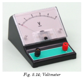
Voltmeter
A voltmeter is a device which is used to measure electric potential difference between two points in an electrical circuit. Electric p.d. is measured in along a calibrated scale in proportion to circuit voltage. Digital voltmeters are now frequently used to give a display of voltage using ADC. A voltmeter is always connected in parallel to the component across which p.d. is to be measured.
5.4 SIMPLE POTENTIOMETER CIRCUITS
A simple potentiometer is a device used for taking a number of electrical measurements. It is a piece of resistance wire, usually a meter long, fixed between two points A and B with a cell of output voltage, V, connected between the two ends.
The potential difference to be measured is put into a circuit together with an opposing variable p.d. from the voltage divider. The voltage divider is then adjusted until its p.d., VAC equals the p.d. being measured. Fig. 5.15 illustrates this.

The sliding contact in the above diagram is moved until the galvanometer indicates zero. This position is referred to as the balance point. The current in the lower part of the circuit is zero because the p.d., VAC equals the p.d. E provided by the cell under test. The protective resistor serves only to prevent the galvanometer from the damage.
Electromotive force of the wire is always proportional to the length of the wire. So, the approximate value of E is determined as follows:

EXAMPLE 5.4
A potentiometer is set up as shown in the Fig.5.16 and the balance point for the unknown e.m.f., E is found at 84 cm from the left hand end of the meter wire. If the driver cell has e.m.f. of 1.5V and negligible internal resistance, find the value of unknown e.m.f.


EXAMPLE 5.5
What value of resistance is needed in series with a driver cell of negligible internal resistance and approximately 3V e.m.f. to arrange that
 of the
  slide wire is required to balance a p.d. of 1.5V?

5.4.1 Comparison of e.m.f.s
A potentiometer may sometimes be used to compare e.m.f’s of a cell with that of a standard cell. Consider the circuit of Fig. 5.18 below.


So if the standard e.m.f. E0 is known, lengths l0 and l are known, then E1 can be calculated.
EXAMPLE 5.6
In Fig.5.19, AB is a uniform wire of length 1.2 m and resistance 8 W. A driver cell of e.m.f. 3V and internal resistance 1W is driving a current Ip as shown. Calculate the e.m.f. of the cell Ex if the balance length is 66.5 cm.


5.6.2 Measurement of internal resistance of a cell
The circuit is arranged as shown in Fig. 5.20 with the cell, whose internal
resistance r is to be found, is connected in parallel with a resistor with resistance R and a switch. The driver cell as usual is in the upper loop of the circuit.

The balance point l is found with the switch open. Since at balance point, no current is flowing through G; E is then measured. The switch is then closed and the new balance point l1 is found. Balance length l1 is proportional to output voltage V (across the resistor R); i.e.

EXAMPLE 5.7
In the circuit of Fig. 5.21 below, AB is a uniform wire of length 1m and resistance 4.0 W. C1 is an accumulator of e.m.f. 2 V a negligible internal resistance. C2 is a cell of e.m.f. 1.5 V.

(a) Find the balance length AD when the switch is open.
(b) If the balance length is 75.0 cm when the switch is closed, find the internal resistance of C2.


(b) When the switch is closed, the internal resistance of the cell can be calculated from equation 5.15.
5.5 MEASUREMENT OF CURRENT BY POTENTIOMETER
Consider the circuit of Fig. 5.22 shown below. Current through a resistor can be calculated at the balance point.
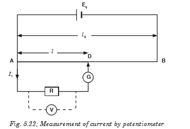
The potential difference, p.d. across R can be found by finding the balance point on the potentiometer such that if the balance point is at C then VAC balances the p.d. across R. If R is known, then the current can be found.


EXERCISE 5.1
1. A potentiometer is set up as shown in Fig. 5.25. Given that the balancing point for the unknown e.m.f. E is found to be 74.5 cm from the left hand end of the meter wire (1m). If the driver cell has an e.m.f. of 1.5 V and negligible internal resistance. Find the value unknown e.m.f.

2. A certain cell is connected to a potentiometer and a balance point is obtained at 84 cm along the meter wire. When its terminals are connected to a 5W resistor, the balance point changes to 70 cm. Calculate the balance when a 5W resistor is now replaced by a 4W resistor.

5.6 ADVANTAGES AND DISADVANTAGES OF POTENTIOMETER
Wear: Most potentiometers last only a few thousand rotations before the materials wear out. Although it means years of service in some applications, it takes special designs to stand up to daily, demanding use. It means they can’t be used for machine sensing where rapid cycling would wear them out in a matter of minutes.
Noise: The action of the wiper moving across the element creates a noise called “fader scratch.” In new pots, this noise is inaudible, but it can get worse with age. Dust and wear increase the bumpiness of the action and make the noise noticeable. Small cracks can appear in the element, and these make noise as the wiper moves over them.
In addition to these mechanically caused noises, carbon elements, in particular, are prone to producing electrical noise. This noise is heard as a soft, steady hiss that can degrade sound recordings. The resistive materials have improved over the years, so newer pots are quieter.
Inertia: The friction between the potentiometer’s wiper and resistive element creates a drag or inertia that the pot must overcome before it turns. Although this drag is not large, it prevents the pot from being used as a rotary sensor in more sensitive applications.
Limited Power: Out of necessity, most potentiometers can dissipate only a few watts of power. To handle more power, they have to be larger and hence expensive. Engineers work around this problem by putting the potentiometer in low-power parts of circuits. They control small currents, which, in turn, control transistors and other components with greater power ratings.

1. What are Kirchhoff’s rules for understanding a circuit?
2. Explain why Kirchhoff’s junction rule must be true if the Law of Conservation of Charge (that no charge may be created or destroyed) is true.
3. Explain why Kirchhoff’s loop rule must be true if the Law of Conservation of Energy is true.
4. Find the branch currents of the circuit shown below.

5. Solve the circuit for currents I1, I2, and I3, using Kirchhoff’s rules.

6. Find the current flowing in the resistor R3 of 40W.


Kirchhoff’s laws
There are two Kirchhoff’s laws: Kirchhoff’s Current Law states that “the algebraic sum of the currents flowing at a node or junction in an electric circuit is zero.”
Kirchhoff’s Voltage Law states that “the algebraic sum of the potentials around a closed electric circuit is zero.”
To solve the resistor circuits using Kirchhoff’s rules
1. Define the various currents
• Can either define branch (segment) currents for each element in the circuit
• Or can define loop currents for each loop in the circuit
2. If using branch currents, use Kirchhoff’s Junction Rule to look for interdependent currents. This allows for reducing the number of variables being solved for.
3. Use Loop Rule to define voltage equations for each loop, using previously defined currents.
4. Solve set of simultaneous equations using algebraic manipulation. A simple potentiometer is a device used for taking a number of electrical measurements. It is a piece of resistance wire, usually a metre long, fixed between two points A and B with a cell of output voltage, V,
connected between the two ends.
Potentiometer can be used to
(i) compare e.m.f.’s of two primary cells.
(ii) measure internal resistance of a cell.