General
- Physics S5 SB File Uploaded 28/01/22, 13:51
- Physics S5 TG File Uploaded 4/01/24, 11:45
UNIT13: INTERFERENCE OF LIGHT WAVES
UNIT13: INTERFERENCE OF LIGHT WAVES
Topic Area: ELECTROMAGNETIC WAVES
Sub-Topic Area: EM WAVES AND INTERFERENCE OF LIGHT
Key unit competence:By the end of the unit I should be able to perform experiment for interference of light waves.
Unit Objectives: By the end of this unit learners will be able to;
◊explain the concept of wave interferences and their applications in our daily life.
◊explain the interaction of electromagnetic radiations with the earth.

13.0. INTRODUCTION
Sun is a nuclear fireball spewing energy in all directions. The light that we see it simply one part of the energy that the Sun makes that our eyes can detect. When light travels between two places (from the Sun to the Earth or from a flashlight to the sidewalk in front of you on a dark night), energy makes a journey between those two points. The energy travels in the form of waves (similar to the waves on the sea but about 100 million times smaller)—a vibrating pattern of electricity and magnetism that we call electromagnetic energy. If our eyes could see electricity and magnetism, we might see each ray of light as a wave of electricity vibrating in one direction and a wave of magnetism vibrating at right angles to it. These two waves would travel in phase and at the speed of light.
13.1. NATURE OF ELECTROMAGNETIC WAVES
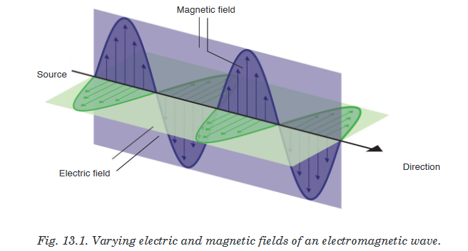
Electromagnetic waves are transverse waves that transfer electrical and magnetic energy. An electromagnetic wave consists of vibrating electric and magnetic fields that move through space at the speed of light. In other words electromagnetic waves have electric and magnetic fields varying perpendicularly as shown on Fig.13.1.
13.1.1 Producing electromagnetic waves
Electromagnetic waves are produced by charged particles and every charged particle has an electric field surrounding it. The electric field produces electric forces that can push or pull on other particles.When a charged particle moves, it produces a magnetic field which exerts magnetic forces that act on certain materials.When this charged particle changes its motion, its magnetic field changes and causes the electric field to change. When one field vibrates, so does the other and the two fields constantly cause each other to change and this produces an Electromagnetic wave.Many properties of electromagnetic waves can be explained by a wave model and some other properties are best explained by a particle model. Both a wave model and a particle model are needed to explain all of the properties of electromagnetic waves and in particular light.
13.1.2 Electromagnetic Radiation
Water waves transmit energy through space by the periodic oscillation of matter (the water). In contrast, energy that is transmitted, or radiated, through space in the form of periodic oscillations of electric and magnetic fields is known as electromagnetic radiation. In a vacuum, all forms of electromagnetic radiation—whether microwaves, visible light, or gamma rays—travel at the speed of light (c), this is about a million times faster than the speed of sound.All forms of electromagnetic radiation consist of mutually perpendicular oscillating electric and magnetic fields. Because the electromagnetic radiations have same speed (c), they differ only in their wavelength and frequency.
13.1.3 Electromagnetic spectrum
When you tune your radio, watch TV, send a text message, or pop popcorn in a microwave oven, you are using electromagnetic energy. You depend on this energy every hour of every day. Without it, the world you know would not exist.Electromagnetic energy travels in waves and spans a broad spectrum from very long radio waves to very short gamma rays. The human eye can only detect only a small portion of this spectrum called visible light. A radio detects a different portion of the spectrum, and an x-ray machine uses yet another portion.

Generation, properties and uses of those waves are summarized in the table below:


ACTIVITY 13-1: Spectrum of Electromagnetic Waves
Aim: In this activity, you will investigate the spectrum of visible light
Materials needed: a white sheet of paper, a glass prism and colored pencils
Shine a light through a prism so that the light leaving the prism falls on an unlined piece of paper. What colours do you see?
As you hold the prism and light steady, your partner will use coloured pencils to draw the colours on the piece of paper. Switch places with your partner. Again, trace the colours you see onto the piece of paper.
◊ What colours do you see on the paper? What is the order of the colours?
◊ Is it difficult to see where one colour ends and the next begins?
◊ Did the order of the colours on the paper ever change?
◊The term spectrummeans a range.
How do you think this term is related to what you observed?
13.1.4 Radiation Interaction with the Earth
Radiation that is not absorbed or scattered in the atmosphere can reach the earth and interact with its surface. There are three forms of interaction that can take place when energy strikes, or is incident upon the surface. These are: absorption (A); transmission (T); and reflection (R).
Reflection: Reflected light is perceived by our eye as colour, e.g. chlorophyll in plants reflects green light. All colours of the visible spectrum are absorbed.
Absorption: The incident energy might not get reflected or transmitted but is transformed into another form, such as heat or absorbed by chlorophyll in the process of photosynthesis.
Transmission: When energy propagates through a medium, what is not absorbed or reflected, will be transmitted through. For instance, an ultraviolet filter on a camera absorbs UV rays but allows the remaining energy to expose the film. Changes in density can also slow the velocity of light resulting in refraction such as dispersion through a prism.
13.1.5 Radiation Interaction with the Atmosphere
The Earth’s atmosphere acts as a filter to remove radiations such as cosmic rays, gamma rays, X-rays, UV rays, and large portions of the electromagnetic spectrum through the process of absorption and scattering by gases, watervapour, and particulate matter (dust).
Scattering occurs when particles or large gas molecules present in the atmosphere cause the electromagnetic radiation to be redirected from its original path. There are three types of scattering which take place: Rayleigh Scattering, Mie Scattering, Non-selective Scatter.
Rayleigh scattering refers to the scattering of light off by the molecules of air. It can be extended to scattering from particles of sizes up to about one-tenth of the wavelength of the light. It is Rayleigh scattering of white light by the molecules of the air which gives us the blue sky.

Mie scattering is caused by pollen, dust, smoke, water droplets and other particles in the lower portion of the atmosphere. It occurs when the particles causing the scattering are larger than the wavelengths of radiation in contact with them. Mie scattering is responsible for the white appearance of the clouds, as seen below.

Non-Selective Scattering occurs when the particles are much larger than the wavelength of the radiation. Water droplets and large dust particles can cause this type of scattering and cause fog and clouds to appear white to our eyes because blue, green, and red light are all scattered in approximately equal quantities (blue+green+red light = white light).
13.1.6 Atmospheric Absorption of electromagnetic waves
In addition to the scattering of EM radiation, the atmosphere also absorbs electromagnetic radiation. The three main constituents of atmosphere which absorb parts of solar radiation are Ozone, Carbon dioxide, and Water Vapour.
Ozone serves to absorb the harmful ultraviolet radiations from the sun. Without this protective layer in the atmosphere, our skin would burn when exposed to sunlight. Ultraviolet rays can also cause skin cancer to people.

Carbon Dioxide absorbs the far infrared portion of the spectrum which is related to thermal heating and results in a ‘greenhouse’ effect.
Water Vapour absorbs energy depending upon its location and concentration, and forms a primary component of the Earth’s climatic system.
13.2. CONDITIONS FOR INTERFERENCE WITH TWO SOURCES OF LIGHT
When two waves of exactly same frequency (coming from two coherent sources) travel in a medium, in the same direction simultaneously then due to their superposition, at some points intensity of light is maximum while at some other points intensity is minimum. This phenomenon is called Interference of light.
There are two types of interference: constructive interference and destructive interference.
A constructive interference is produced at a point when the amplitude of the resultant wave is greater than that of any individual wave
A destructive interference is produced at a point when the amplitude of the resultant wave is smaller than that of any individual wave.
Conditions for interference
When waves come together they can interfere constructively or destructively. To set up a stable and clear interference pattern, two conditions must be met:
• The sources of the waves must be coherent, which means they emit identical waves with a constant phase difference.
• The waves should be monochromatic - they should be of a single wavelength.
13.3. PRINCIPLE OF SUPERPOSITION
The principle states that when two or more than two waves superimpose over each other at a common particle of the medium then the resultant displacement
of the particle is equal to the vector sum of the displacements (y1 and y2) produced by individual waves. i.e.
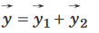
Consider two waves given as:
y1 = a1 sin wt and y2 = a2 sin (wt + f);
where a1, a2 = Individual amplitudes, f = Phase difference between the waves at an instant when they are meeting a point. I1, I2 = Intensities of individual waves
After superimposition of the given waves resultant amplitude (or the amplitude of resultant wave) is given by;

13.4. INTERFERENCE PATTERN OF TWO COHERENT POINT SOURCES OF LIGHT
The sources of light which emit continuous light waves of the same wavelength, same frequency and are in same phase (or have a constant phase difference) are called coherent sources. Two coherent sources are produced from a single source of light by using Young’s double slits.

From the Fig. 13.7. S1 and S2 are coherent sources and show interference as light passes through two slits. It also shows the appearance of the interference pattern on a screen placed in the path of the beam. You can see the maxima and minima and the way in which the intensity changes.Changing the wavelength of the light, the separation of the slits or the distance of the slits from the screen will all give changes in the separation of the maxima in the interference pattern.
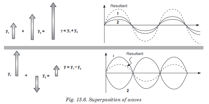
13.5. YOUNG'S DOUBLE-SLIT EXPERIMENT
Monochromatic light (single wavelength) falls on two narrow slits S1 and S2 which are very close together and act as two coherent sources. When waves coming from two coherent sources superimpose on each other, an interference pattern is obtained on the screen. In Young’s double slit experiment alternate bright and dark bands are obtained on the screen.
These bands are called Fringes.

Following points must be noted and observed in the above experiment:
• Central fringe is always bright, because at central position, f = 0° or the path difference D = 0
• The fringe pattern obtained due to a slit is more bright than that due to a point.
• If the slit widths are unequal, the minima will not be completly dark. For very large slit width, uniform illumination occurs, i.e. bright and dark fringes are not formed.
• If one slit is illuminated with red light and the other slit is illuminated with blue light, no interference pattern is observed on the screen.
• If the two coherent sources consist of object and its reflected image, the central fringe is dark instead of bright one.
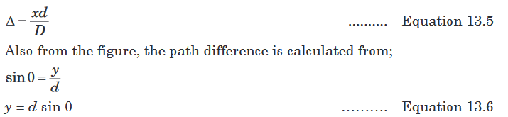
Calculation of fringe separation/fringe width
Consider two coherent sources (slits) S1 and S2 separated by distance d.
The distance D from the plane of slits to the screen is much greater than d.
Consider a wave from S1 that meets another wave from S2 at point P.


Position for the dark and bright fringes
Note that a fringe is a region of net interference. A bright fringe is obtained when the path difference is a whole number of wavelength.

Notes
• x is fringe separation and its value increases by decreasing the slit separation a.

• Increasing the width of the slits increases the intensity of waves and fringes become more blurred.
13.6. INTENSITY DISTRIBUTION OF FRINGE PATTERN
So far we have discussed the locations of only the centers of the bright and dark fringes on a distant screen. We now direct our attention to the intensity of the light at other points between the positions of maximum constructive and destructive interference. In other words, we now calculate the distribution of light intensity associated with the double-slit interference pattern.

Again, suppose that the two slits represent coherent sources of sinusoidalwaves such that the two waves from the slits have the same angular frequency w and a constant phase difference F. The total magnitude of the electric field at point P on the screen is the vector superposition of the two waves. Assuming that the two waves have the same amplitude E0, we can write the magnitude of the electric field at point P due to each wave separately as;

This result indicates that the electric field at point P has the same frequency w as the light at the slits, but that the amplitude of the field is multiplied by the factor
Finally, to obtain an expression for the light intensity at point P, the intensity of a wave is proportional to the square of the resultant electric field magnitude at that point;


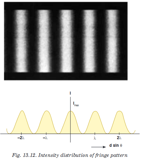
Note that the interference pattern consists of equally spaced fringes of equal intensity. Remember, however, that this result is valid only if the slit-to-screen distance D is much greater than the slit separation d.
EXERCISE 13-1
1. In a double slit interference experiment, the distance between the two slits is 0.0005m and the screen is 2 m from the slits. Yellow light from a sodium lamp is used and it has a wavelength of 5.89 × 10⁻⁷ m. Show that the distance between the first and second fringes on the screen is 0.00233 m.
2. With two slits are spaced 0.2 mm apart, and a screen at a distance of D = 1 m, the third bright fringe is found to be displaced h = 7.5mm from the central fringe. Show that the wavelength,
 , of the light used is 5 × 10⁻⁷m.
3. Two radio towers are broadcasting on the same frequency. The signal is strong at A, and B is the first signal minimum. If d = 6.8 km, L = 11.2 km, and y = 1.73 km, what is the wavelength of the radio waves to the nearest meter?

4. Water waves of wavelength of 5.44 m are incident upon a breakwater with two narrow openings separated by a distance 247 m. To the nearest thousandth of a degree, what is angle corresponding to the first wave fringe maximum?

UNIT SUMMARY
Nature of electromagnetic waves
Electromagnetic waves are transverse waves that transfer electrical and magnetic energy. In other words electromagnetic waves have electric and magnetic fields varying perpendicularly.
Producing electromagnetic waves
Electromagnetic waves are produced by charged particles and every charged particle has an electric field surrounding it. The electric field produces electric forces that can push or pull other particles.
Electromagnetic Radiation
All forms of electromagnetic radiation consist of perpendicularly oscillating electric and magnetic fields. Various kinds of electromagnetic radiations have the same speed (c). They differ only in wavelength and frequency.
Electromagnetic energy travels in waves and spans a broad spectrum
from very long radio waves to very short gamma rays. This is called electromagnetic spectrum.From memory you should be able to list the parts in order of energy (relate how that relates to frequency and wavelength) and know how they are produced, detected and their dangers and uses - a rough idea of their approximate wavelength is also useful!
Radiation Interaction with the Earth
Radiation that is not absorbed or scattered in the atmosphere can reach and interact with the Earth’s surface. There are three forms of interaction that can take place when energy strikes, or is incident upon the surface. These are: absorption (A), transmission (T) and reflection (R).
Radiation Interaction with the Atmosphere
The Earth’s atmosphere acts as a filter to remove radiation such as cosmic rays, gamma rays, X-rays, UV rays and large portions of the electromagnetic spectrum through the process of absorption and scattering by gases, watervapour and particulate matter (dust).
Atmospheric Absorption of electromagnetic waves
In addition to the scattering of EM radiation, the atmosphere also absorbs electromagnetic radiation. The three main constituents which absorb radiation are Ozone, Carbon Dioxide and Water Vapour.
Conditions for interference to occur
• The sources of the waves must be coherent, which means they emit identical waves with a constant phase difference.
• The waves should be monochromatic - they should be of a single wavelength.
Principle of superposition
The principle states that when two or more than two waves superimpose over each other at a common particle of the medium then the resultant displacement

Double-slit experiment
Monochromatic light (single wavelength) falls on two narrow slits S1and S2 which are very close together acts as two coherent sources, when waves coming from two coherent sources superimposes on each other, an interference pattern is obtained on the screen
A bright fringe is obtained when the path difference is a whole number of wavelength.

Intensity distribution of fringe pattern
Assuming that the two waves have the same amplitude E0, we can write the magnitude of the electric field at a point let say P due to each wave separately as;
