UNIT 3 :NETWORKING PROJECT
UNIT 3: NETWORKING PROJECT
Key Unit Competency:To be able to build a computer wired and wireless network
INTRODUCTORY ACTIVITYObserve the following figure
Figure: 3.1: Networking tools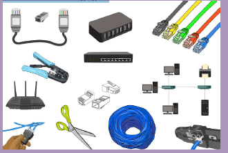
Observe the figure above and answer the following questions
1. List all the medium in the figure above
2. Using two telephones or two laptops state different steps which can help sharing films via Bluetooth technology.
3. Choose the different tools which can help in crossover Network cable making4. Describe all network tools available in the school computer Lab and in the figure 3.1
3.1 Build Peer to Peer network
Project I: Preparing Ethernet cables and devices
P2P Project 3.1. A
1) You are given 10 computers, UTP cables, RG-45, crimping tools, switch/ hub
a. Arrange the tools and devices required to build P2P network
b. Prepare cables required to build P2P network
c. Test each cable if they are properly working.
d. Connect cables to different devices.
e. How will you dispose your useless materials?
f. To avoid the loss of many materials which are costly, what measures would you
take?
Observation: If you have a green light, the connection is successful; if the
color is Red, the connection is failed, please revise you cabling. If tried twicewithout success, please call the teacher/Lab technician.
3.1.1 Tools required building P2P Network
This practice has crucial important as when files are shared to the network will reduce
the cost of printout papers as one document can be shared by many users who
stands in the same P2P network or when sharing printer to the same P2P network,
all users can enjoy printing without taking time in installing setup to all computers
in the same work group.
In order to build peer to peer network we need several equipment discussed in
previous network classes, the maximum number of computer to build a P2P network
is 10, transmission media needed is UTP cables. We use crossover to connect the
same devices (hub to hub, computer to computer, router to router, and switch to
switch) and straight through cable to connect different devices (Computer to switch,
computer to hub). We use star topology where we need Switch/hub as the central
devices. To build a P2P network of 2 computers we need only two computers and
Ethernet cable (Strait through cable), for P2P network of more than 2 computers we
need computers, Ethernet cables (Crossover and Straight through) and Switch/hub.
3.1.2 Process to build P2P network
We are going to build a peer to peer network for small office or home office.
Step 1: Make sure all computers are turned off, organized and arranged.
In this practice we need to arrange 10 computers which is the maximum number of
computer allowed in P2P network.Step 2: Install central devices (Switch or hub).
Step 3: Connect each end of the UTP CAT 6 straight through cables to connect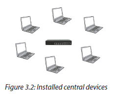
computers to Switch/ Hub.
When connecting devices, UTP CAT 6 straight through cable is required to connect
the same devices (Computer to computer) and UTP CAT 6 crossover cable to connect
different devices (Switch to computer), depending on number of devices we have in
our practice, more Ethernet cables are need. There are some tools which are needed
to make ethernet cables and different steps learned in the previous school (S5, Unit
3 Introduction to networking) are needed.
Tools used to make Ethernet cables: cat 6 cables, RJ 45 , RJ 45 crimping tool, scissors,
Cable tester, drilling machine, hammer, screw driver, cable strripper, cable ducts
Making straight through cable and Crossover cable:
Step 1: Strip the cable jacket about 1.5 inch down from the end.
Step 2: Spread the four pairs of twisted wire apart. For Cat 5e, you can use the pull
string to strip the jacket farther down if you need to, then cut the pull string. Cat 6
cables have a spine that will also need to be cut.
Step 3: Untwist the wire pairs and neatly align them in the T568B orientation. Be
sure not to untwist them any farther down the cable than where the jacket begins;
we want to leave as much of the cable twisted as possible.
Step 4: Cut the wires as straight as possible, about 0.5 inch above the end of the
jacket.
Step 5: Carefully insert the wires all the way into the modular connector, making
sure that each wire passes through the appropriate guides inside the connector.
Step 6: Push the connector inside the crimping tool and squeeze the crimper all the
way down.
Step 7: Repeat steps 1-6 for the other end of the cable.
Step 8: To make sure you’ve successfully terminated each end of the cable, use a
cable tester to test each pin.
The following figure shows how you should keep each wire according to their colorsfor each type of cable (Crossover and straight through cables)
You should also use numbers of wires in case you are confused by colors. The following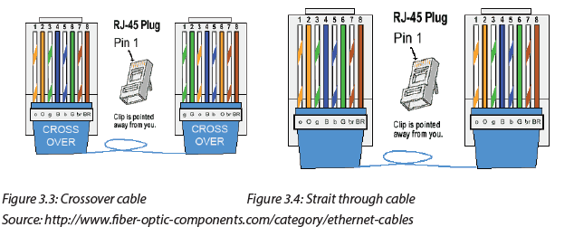
figure helps also to create the indicated cables.
a. Straight Cable
After making Ethernet cable we need to make them tested using cable tester using packet
tracer, we can connect devices using different cables not only packet tracer which can beused but also real computers depending on the resources/ computer lab.
Project II: Static IP address configuration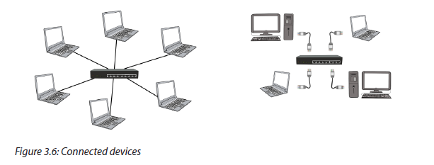
P2P Project 3.1. B
Using previous exercises P2P project 3.1.A, after arranging computers and connect
them with different cables accordingly do the following:
a. Define IP address scheme to be used
b. Assign each computer a static IP address
c. After assigning static IP address, test if they are connected using ping
command.
d. Identify the materials to be used for keeping devices clean.
Observation: By pinging each computer, the observation will be on the replies, if IP
address is assigned successfully, the packet sent will be equal to 4, received will be 4
and the lost will be 0, else it is not assigned successfully else repeat the process. If failedtwice call the teacher/Lab technician for guidance.
Step 4: Define IP address scheme
Listing IP addresses that will be used to different computers is an important step
that will be helpful to define the same working group for being able to share files,
folder, printers and network.
In this project we use maximum 10 computers which are allowed to build P2P
network, the IP addresses given to the PCs can be in the same network for being inthe same work group to share resources such as folder, printer, files and network.
The following are IP addresses we will use in this practice:
PC1: 192.168.0.1, PC2: 192.168.0.2, PC3: 192.168.0.3, PC4: 192.168.0.4,
PC5: 192.168.0.5, PC6: 192.168.0.6, PC7: 192.168.0.6, PC8: 192.168.0.8,
PC9: 192.168.0.9, PC10: 192.168.0.10
Step 5: Configure static IP address for each computer.
Process1: In windows 10, go to search and type in Control panel and click on it
Process2: Click the link “View network status and tasks” under the “Networkand Internet” heading.
Process 3: Click the link on the left of the window labeled Change adapter settings.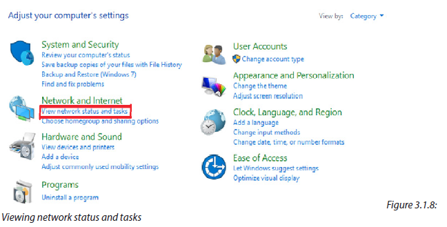
Process 3: change adaptor settings
Process 4: You might have more than one Internet connection listed in this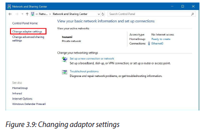
window. If this is the case you will need to determine which one is your connection
to the Internet. Once you have found it, right click on your network adapter andchoose properties to open up the properties window of this internet connection.
Process 5: Find the option of Internet Protocol Version 4 (TCP/IPv4) and click on
it. Then choose one option (Internet Protocol Version 4)
Process 6: Select “Use the following IP address” and enter the IP address,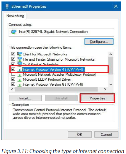
Subnet Mask, Default Gateway and DNS server. Click OK and close the Local AreaConnection properties window.
When choosing “Use the following IP address” the IP must be configured as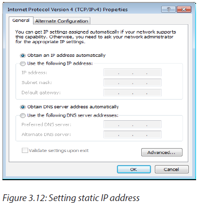
Static
Procces7: As an example, assign one PC1 an IP address of 192.168.0.1 and use the
subnet mask 255.255.255.0.For PC1
Procces 8: As an example, assign one PC2 an IP address of 192.168.0.2 and use the
subnet mask 255.255.255.0.
For PC2
Process 9: Do the same for other 8 PCs
Step 6: Ping each computer to verify if they are connected
Process 1: In windows 10, go to search and type in CMD then press Enter
Process 2: Type Ping 192.162.0.1 (if you use a computer assigned with
192.168.0.2 type in: ping 192.168.0.2) then press Enter button, the replies shouldbe as indicated in the figure below
Figure 3.1.15: IP address Replies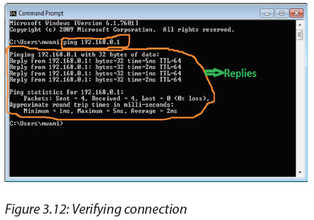
Step 7: Do the same as what you did on step 5 to all PCs
Note: if you receive timeout message when attempting to ping your selected IP
address, it is possible that the internet connection firewall is interfering, unpluggedcables, mistake on IP configuration, etc
How to allow internet connection through the firewall?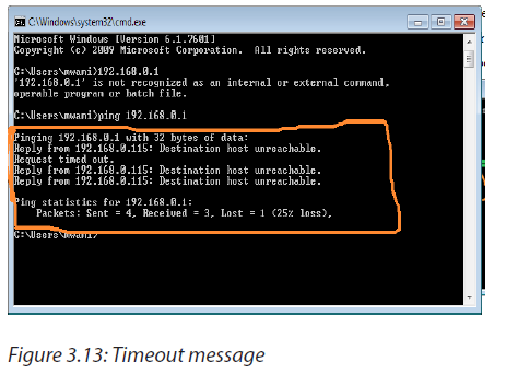
- Right click on My Network places, then select properties.
- Right click local Area connection and select properties once again,
- Click the advanced tab. Uncheck the box titled: protect my computer from
the internet.
- Click OK. Now, try typing the selected IP address again.
Once you get two computers to communicate successfully together, you can nowenjoy the benefit of files, printer, internet sharing.
Project III: Sharing folder, files, printer and internet
P2P Project 3.1.C
Using previous exercises P2P project 3.1.B, after assigning each computer its own IP address,
do the following
a. Put all computers in the same work group network
b. Share files, folder, printers and network.
c. How to avoid piracy in networking.
Observation: When files, folder, printer and internet are successfully to all permitted PCs,
they should be seen and retrieved on other PCs and enjoying using them when you are
in the same P2P network. The shared printer must print to every connected PC even if
there is no setup installed. If fails to share repeat the process once else call to the teacher/Lab technician for guidance
To share folder requires creating a home group/ workgroup, for the topic discussed
in S5, creating home group/ work group is discussed, here we need to change a
home group/ work group to be able to share files, folder, printer and network.
The following are the steps to change the home group/ workgroup in Windows 10
Step1: With the right mouse button click the Start icon and choose System. If you
have a touch enabled device, click and hold the start button, then tap the Systembutton.
Step2: Under “Computer name, domain, and workgroup settings” click on Change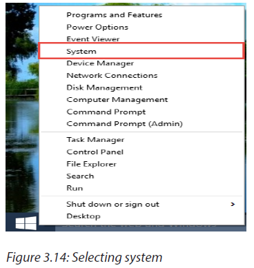
Settings
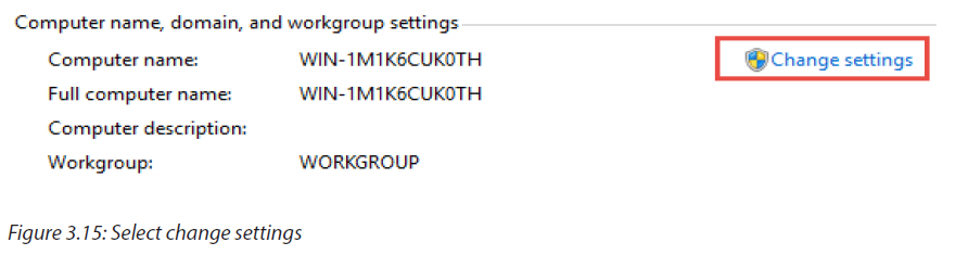
Step3: Under the tab “Computer Name” find the Change… button and click it
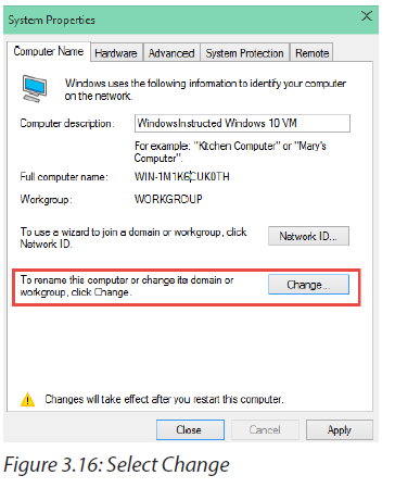
Step4: Under “Member Of” change the Workgroup name.
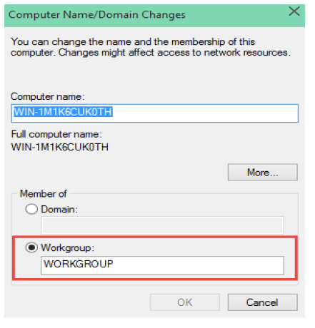
Figure 3.17: Select workgroup
Step 5: Change the name from WORKGROUP to S6A
Step 6: Then click on OK, the system will prompt to reboot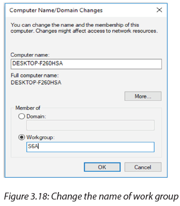
After rebooting the system, the new folder/files/printer or network will be added
to the existing Home group following the steps below
Step 1: Use the Windows key + E keyboard shortcut to open File Explorer
Step 2: On the left pane, expand your computer’s libraries on Home Group
Step 3: Right-click Documents and choose Properties
Step 4: Click Properties.Step 5: Click Add.
Step 6: Select the folder you want to share and click Include folder.
Step 7: Click Apply.
Step 8: Click OK.
Now the folder will be accessible by anyone who joined the Home Group when
they browse the Documents folder
3.2 Wireless Router installation and configuration
Note: This configuration is for TP-Link wireless Router, for other types of wireless
routers, consult manufacturer requirements and guidance.
Project I: Wireless router connection and Setting
P2P Project 3.1.C
Using previous exercises P2P project 3.1.B, after assigning each computer its own IP
address, do the following
a. Put all computers in the same work group network
b. Share files, folder, printers and network.
c. How to avoid piracy in networking.
Observation: When files, folder, printer and internet are successfully to all permitted PCs,
they should be seen and retrieved on other PCs and enjoying using them when you are
in the same P2P network. The shared printer must print to every connected PC even if
there is no setup installed. If fails to share repeat the process once else call to the teacher/
Lab technician for guidance
This unit provides procedures for configuring the basic parameters of your router;
it also describes the default configuration on startup.
3.2.1 Default configuration
When you first boot up the router, some basic configuration has already been
performed for TP-Link wireless router. All of the LAN and WAN interfaces have been
created, console and VTY (Virtual Teletype) ports are configured, and the inside
interface for Network Address Translation has been assigned.
3.2.2 Wireless Router configuration requirements
For some routers web browsers are needed to configure them to the wireless
router, others need Ethernet cables to be configured, they are also some which
needs their catalog where there is written all process to configure them.
To configure wireless Router the following materials are needed:
• A wireless router,
• A computer or laptop with wireless capabilities.
• Two Ethernet cables.
Step 1: Prepare router and switch on it.
Step2: Connect router to the Laptop/PC with wireless capability
Step3: Access Dashboard using default IP address and Password
The different process will be applicable when prompting to the Dashboard using
default IP and password.
Process1: Open the web browser and key in the address bar the default IP address
(192.168.0.1)
Process2: The server asks for the default username and password. The user willthen write in the form the default username and password
Process 3: Prompting default dashboard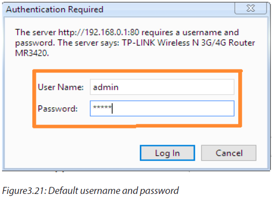
The figure below will be displayed after entering default username and password
Step4: Configure internet using information from the ISP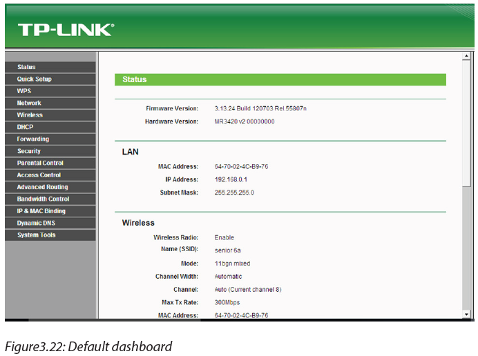
When configuring internet using information from ISP, some processes are
applicableProcess1: Click on Network then select internet mode and click Save
Process2: Click on Quick Setup to start configuring internet using information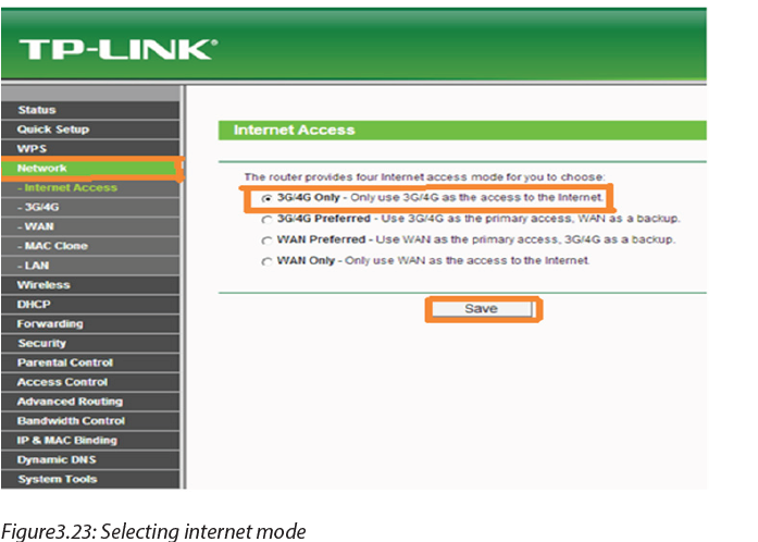
from ISP where the selected internet mode is activated, then click Next.
Process3: On Wireless name rename the existing name of wireless and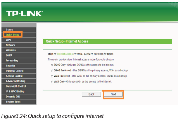
authenticate by set your own password for network protection.
In this practice, we use
Wireless name: senior 6aPassword: Kigali12
Process 3: After renaming Wireless and authentication, click Finish to apply the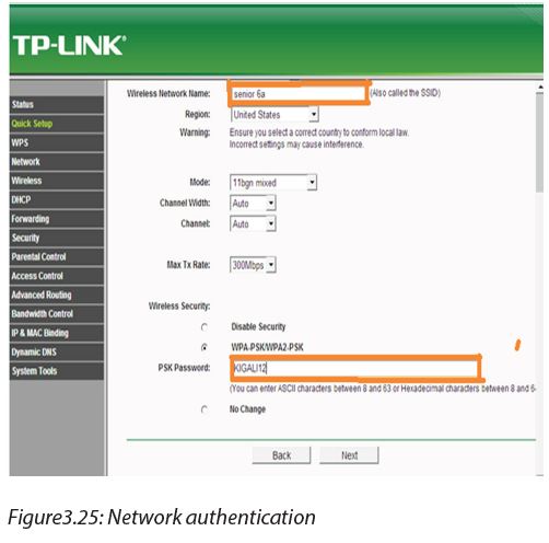
change, and then move to set DHCP settings.
Project II: Wireless security configuration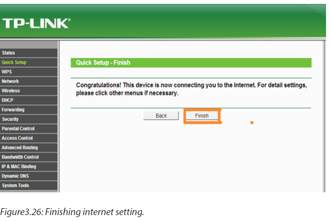
Wireless Router configuration Project 3.2.B
Following what is done in Wireless Router 3.2.A
a. Configure the wireless security
b. Set DHCP settings?
c. What measures would you take to keep data on router confidential?
Observation: If wireless router is successfully configured it will be seen on each device
which has capabilities to be connected to the wireless and using the name of the wireless
and password connect to verify if it is working, if it is not working repeat configurationonce if fails twice, call to the teacher for guidance.
Step5: configure LAN and IP using DHCP
Go to Wireless then Wireless Security and configure the wireless security. WPA/
WPA2-Personal is recommended as the most secure option. Once configured,
click Save.
There are many wireless security protocols. Here is a basic list ranking the current
Wi-Fi security methods available on any modern (post-2006) router, ordered from
best to worst: WPA2 + AES, WPA + AES, WPA + TKIP/AES (TKIP is there as a fallback
method), WPA + TKIP, WEP and Open Network (no security at all).
Ideally, you will disable Wi-Fi Protected Setup (WPS) and set your router to WPA2
+ AES. Everything else on the list is less than ideal step down from that. Once you
get to WEP, your security level is so low, it’s about as effective as a chain link fence.
The fence exists simply to say “hey, this is my property” but anyone who actuallywanted to go in could just climb right over it.
Note: If using a dual band router, repeat this process.
Step 5:
Go to DHCP→ DHCP Settings and select Disable the DHCP Server. Clickon Save.
Step 6: Set the IP from ISP and go to the System Tools and select Reboot to reboot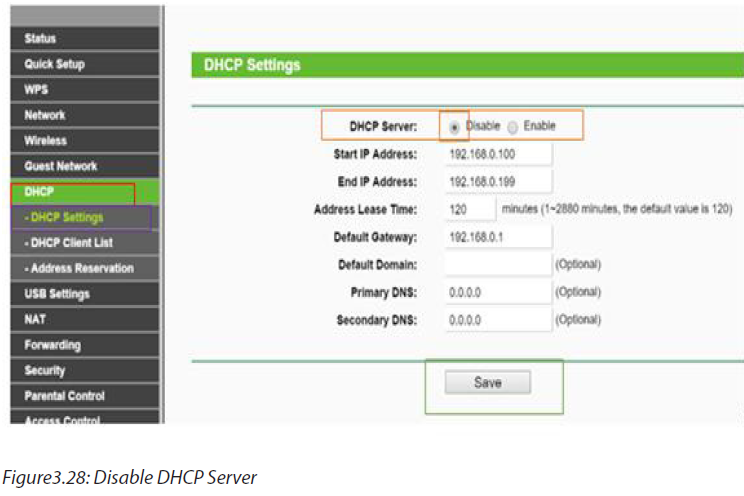
the device.
3.3 Building Client/Server network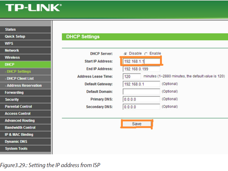
Project I: Creating and setting an FTP folder
Client/server project 3.3.A
1. You are given 2 computers and strait through cables
a. Create an FTP Folder
b. Configure IP address
c. Configure an FTP Server
d. When file is needed to be used by many people in the group, sometimes
printing or sending to flash disk is needed which is costly and sometimes
spread viruses. What measures would you take to avoid high cost and
virus spreading?
Observation: If the FTP folder is successfully created it will be available on server computer
and start enjoying using it for the next session to create an FTP site. If it fails once,call to the teacher/lab technician for guidance.
3.3.1 Creating an FTP client/server network
With a home FTP server, you are able to upload and download files from anywhere
to your PC, Similar to cloud storage but without the limitations.
Setting up a File transfer protocol (FTP) server may sound complicated, but it’s
actually quite easy to set up especially if using Windows 10.Step 1: Create a folder that your FTP users will be accessing on C: drive.
Step2: Press the “Windows key + R” on your keyboard to open the Run window,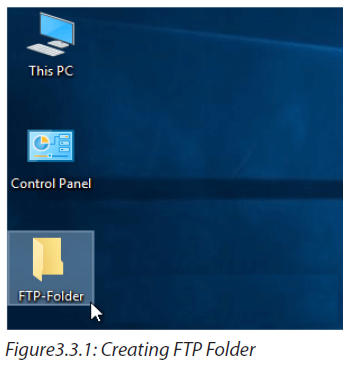
and type CMD, click OK to open the command prompt window.
Step3: Here type “ipconfig” and press enter, write down the IP address and the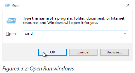
default gateway IP, because we are going to use it in the next steps. Here thefollowing IP addresses will be used: 10.0.0.17 and 10.0.0.1
Step4: Then go to Control Panel -> Programs and Features.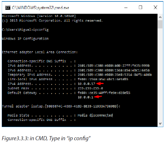
Step5: Navigate to Turn Windows features on or off on the top left.
Step 6: Select the check box, next to “Internet Information Services” also collapse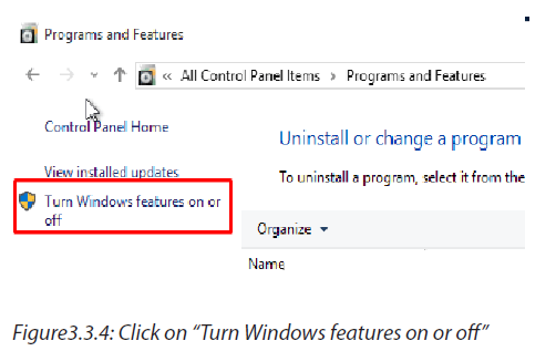
it to check mark “FTP Server” and “FTP Extensibility”, then click the OK button andwait for the features to be added.
Project II: Creating and setting an FTP site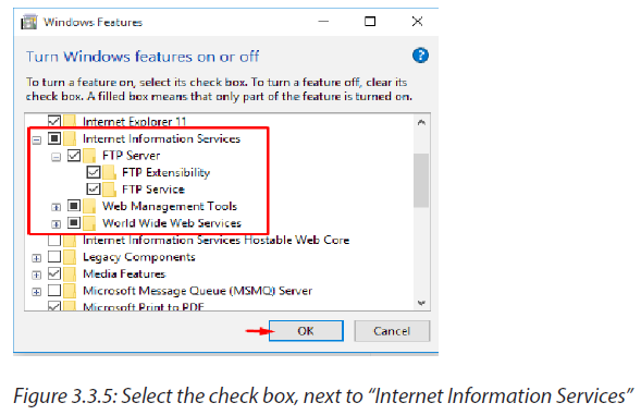
Client/server project 3.3.B
1. Following the steps client/project 3.3.A,
a. Create an FTP site
b. Create an Internet Information service site
c. How can you prevent unauthorized user to access your data?
Observation: If the FTP site is successfully created it will be available on server computer
and start enjoying by sharing folder, printers and files to the same client/server network.If it fails repeat the process or consult the teacher for guidance.
Step 7: Go to Control panel, Administrative tools,
Step 8: Choose Internet Information Services (IIS) Manager,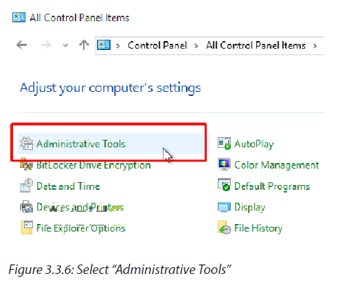
Step 9: Expand the root and right click on Sites to create a new FTP Site, click on“add FTP Site…”
Step10: Give your FTP site a name, such as “AvoidErrors”, and browse for the folder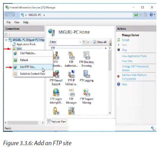
we created initially. This will be the default location where files will be accessible onthe server via FTP.
Step11: On the Binding and SSL Settings page, click on the drop down to select
the IP Address of the computer, Select “No SSL”. If you do have an SSL certificate,you can choose either “Require SSL” or “Allow SSL”.
Note: Be sure to require SSL if you intend to make this FTP server accessible via the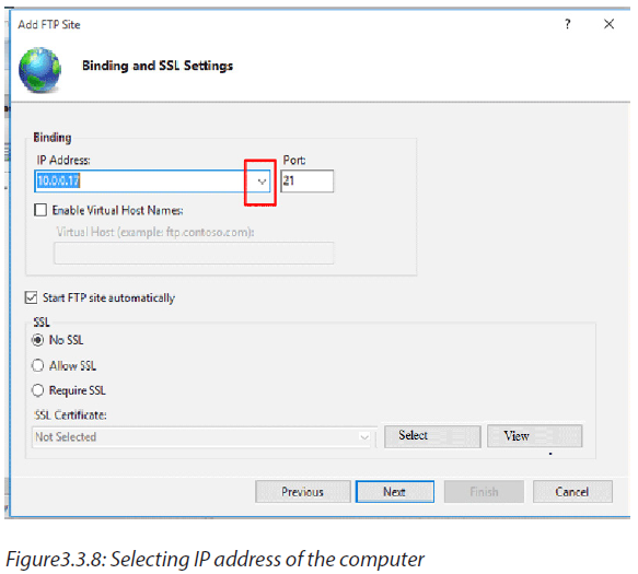
Internet.
On the Authentication and Authorization Information screen, change
“Authentication” option to “Basic” (requires that FTP users specify a login ID and
password).
Step13: Authorization section, select “Specified Users”, and Read & Write
permissions. Alternatively, you can choose specific user accounts or a group, and
limit permission to only Read or Write. Click Finish.Step13: Now your new IIS Site is properly created.
Step14: Create a local user account, and give to him/her permission on the FTP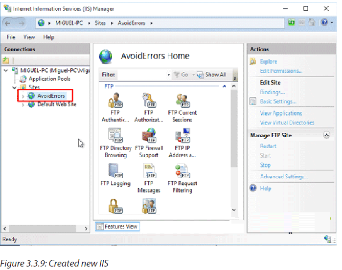
content directory:
*If you prefer to use an already existing local computer user account instead of
creating one you can skip the create user step and skip to open windows firewall
ports.
To allow additional users you must:
1. Create a Windows 10 user.
2. Create a new IIS Rule for the new user.
3. Add the new user to the security settings of the FTP folder.
Open firewall ports for FTP:Open Control Panel… (View by: “Small icons” recommended)… Windows
Firewall… Select “Allow an app or feature through windows firewall” -> Change
Settings button
Select the checkbox next to “FTP Server” and at least one of the networks, and thenclick on OK.
Project III: Creating rules and sharing folders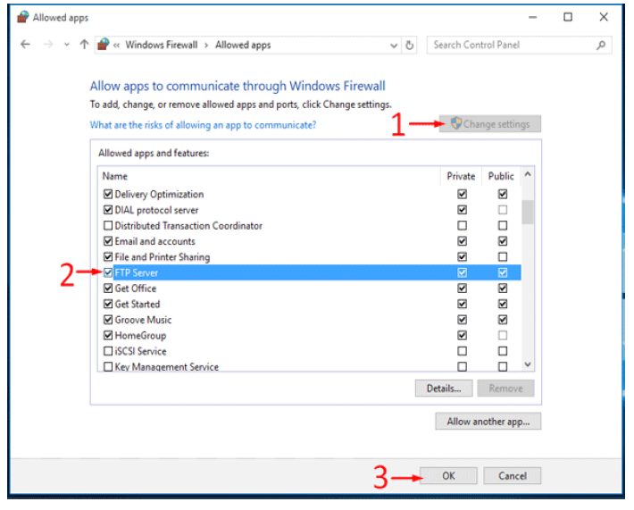
Client/server project 3.3.C
1. Following the project 3.3.B,
a. Enable FTP server port to be accessed from the LAN
b. Select proper management
c. Add the new user to the security settings of the FTP folder.
d. How can you avoid unauthorized users to access your folder
Observation: If the FTP client/server network is successfully configured the shared Folder,
printer, files and internet will be seen among all computers on the same network of
FTP server network, you can start enjoying using the shared files, folder and printers.Else repeat the process twice or call the teacher for guidance.
Now the Windows 10 FTP Server is enabled to be accessed from the LAN.
Step15: Once you have tested the FTP over the LAN than we are ready to access it
via WAN. To allow FTP connection you must enable Port 21 in your router’s firewallto allow incoming connection via FTP port 21.
Process1: Select the proper Site in IIS Manager and on the right, navigate to FTP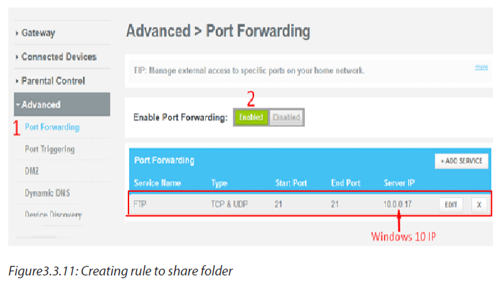
Authorization Rule.
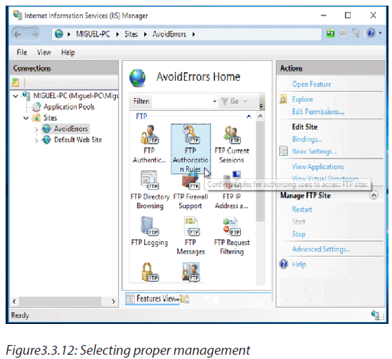
Process2: Right click an empty space and select Add Allow Rule…
Process3: Here check mark specified users and write the user name. Make sure is
first created in windows 10 and click OK.
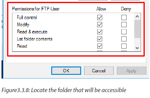
To add the new user to the security settings of the FTP folder:
Process4: Locate the folder that your FTP users will be accessing (example: C:\FTPFolder),right click the folder… select Properties -> Security tab… and add the
user that was created in the previous step with appropriate permissions.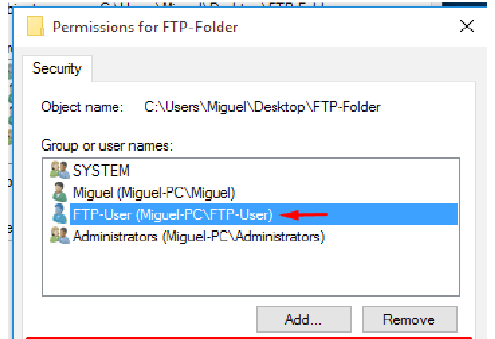
End unit activity
1. Lab activity: a given 5 computers with the following IP addresses:
198.162.0.117, 198.162.0.114, 198.162.0.118, 198.162.0.119,
198.162.0.116, the subnet mask is 255.255.255.0 assigned to all
computers
a. Create a P2P network
b. Add a home group and share folders, music and files to all computers.
2. You are given a server machine, three new laptop, three Ethernet
cables, and the following IP addresses: 198.162.0.12 and 198.162.0.13,create an FTP client/ server network and share folder.