Unit 2:COMPUTER ARCHITECTURE Unit 2 AND ASSEMBLY
Key Unit Competency
By the end of the unit, you should be able to:
• Identify computer components and their functions (input, output, processing and storage.
• Assemble, disassemble computers and perform basic maintenance services.Unit Outline
• Computer system.
• Computer hardware.
• Audio port and connector.
• Internal computer components.
• Assembling computers.
• Cleaning and disposing of computer components.Introduction
This unit introduces us to computer components and their functionality in order to have a common understanding of microcomputers regardless of their physical configuration. Later, the unit focuses on fundamentals of computer architecture that aims at equipping us with practical skills on how to assemble, disassemble, and repair desktop computers.
2.1 Computer System
Though there are various definitions of computer systems, in our context we define a computer system as the combination of hardware, software (programs), user (liveware) and data that forms a complete, working system.2.1.1 User
A computer system is not complete without people referred to as users or liveware. Although some types of computers can operate without much intervention from users, most personal computers are designed specifically for use by people.2.1.2 Hardware
In computer science context, hardware refers to physical components that make up a computer system. Common examples of hardware include system unit, keyboard, mouse monitor, printer, speakers, and modem.2.1.3 Software
The term software refers to a set of instructions also known as program that directs a computer what to do. Some programs operates computer hardware and other programs while others enable a computer user to perform specific tasks such as accounting.2.1.4 Data
Data consists of raw facts which the computer can manipulate and process into information that is useful to the user. In digital computers, data is converted from forms that people can understand such as text, numerals, sounds, and images into binary digit i.e. zeros and ones.
The four components that make up a computer system are illustrated in Fig. 2.1. Note
that the software component is represented by shelved software casings and programs
running in the computer, while data is illustrated by information on the screen and on a piece of paper on the desk.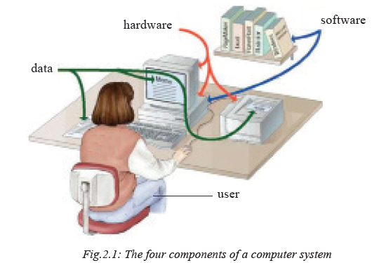
Activity 2.1: Computer Components
Using examples, explain the function of each of the four components of a computer system. Compare your answers with other members of your class and the below following discussion.
2.2 Computer functions
Computers manipulate (process) data (input) to produce information (output) and hold (store) processed information for future use as shown in Fig. 2.2.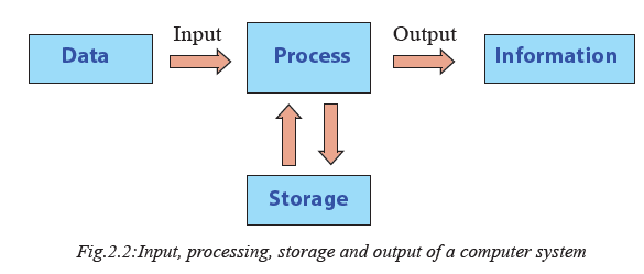
• Input: The first box on the illustration depicts how a computer receives input for processing.
• Process: The computer then performs processing such as calculations and comparisons.
• Output: The computer generates information that may be printed or displayed on a screen or in a specified format.
• Storage: Data and information may be stored for future use on storage devices such as hard disk, CD/DVD etc.2.3 Computer hardware
Generally the main hardware components of a typical desktop computer can be classified into two broad categories namely; peripheral devices as and the system unit.2.3.1 Peripheral Devices
Most desktop computers consist of external devices connected to a central housing known as the system unit. Collectively, external input devices such as keyboard and output devices such as the monitor are referred to as peripheral devices. Fig. 2.3 shows common examples of peripheral devices.Activity 2.2: Peripheral Devices
Fig. 2.3 shows peripheral devices that may be attached to the system unit of a microcomputer.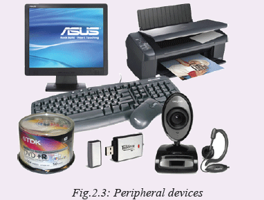
Identify each item and classify it as input, output or storage devices using descriptions given below:
• Peripheral device that enables the user to enter data and instructions into the computer through typing.
• To execute a command, the user moves the mouse which consequently moves the pointer on the screen.
• Television-like device that enables the user to display information such as text and videos from the computer.
• Peripheral device that looks like lever used to control a pointer on the screen mostly used for playing computer games.
• Devices used to display output from a computer onto a hardcopy such as plain papers.
• Peripheral device used to capture digital images and video and directly stores the content into computer storage.
• Peripheral device used to produce audio sound such as music from a computer.
• Secondary storage media/device that can be plugged into USB port to read or store data.
• Shiny round secondary storage media that is inserted into the system unit disk drive to read or store data.2.3.2 Computer case
The computer case, commonly referred to as the system unit, is the main hardware part in which internal components such as microprocessor, computer memory, and drives are housed. In terms of physical appearance (form factor), the two common types of systems units are tower type shown in Fig. 2.4(a) and desktop type in Fig. 2.4(b). The main difference is that, in tower system unit, the monitor rests on the table while in desktop types; the monitor may be placed on top of the system unit.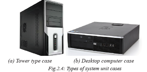
Activity 2.3: System Unit
1. Discuss with your partner what the system unit of a computer is.
2. Identify the types of system units.
3. State the advantage and disadvantages of each of computer cases.2.3.3 Ports and Connectors
A port is a physical or wireless interface between the computer and peripheral devices. Physically, you can identify ports such as shown in Fig. 2.5 through which devices may be connected using interface cables. In this section, we discuss ports such as serial, parallel, universal serial bus (USB), Ps/2, HDMI and VGA shown in Fig. 2.5 (a) and (b).Activity 2.4: Ports and Connector
1. Following the guidelines from the teacher, carefully unplug peripheral devices connected at the back of the computer. Depending on the physical configuration of a system unit, you may observe ports such as the shown in Figure 2.5 below.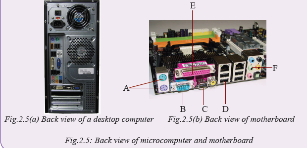
3. Using Fig. 2.5, identify the ports labelled A-F and demonstrate how each port connect peripheral devices to the system unit. Compare your work with the brief description given below:
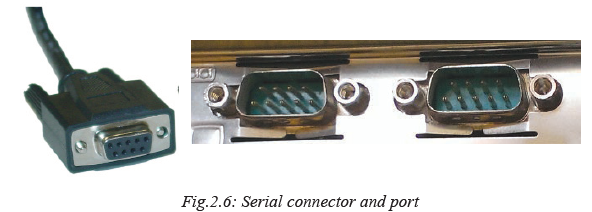
2.3.3.1 Serial port
Serial ports also known as RS232 ports are used to connect devices that transmit and receive data as a series of binary digits (bits). Although RS232 ports and cable shown in Fig. 2.6 have become obsolete, they were used to connect devices such as the mouse, serial modems and printers.
Activity 2.5: Serial Connector
In groups or individually, study the serial connector shown in Fig. 2.6 above and perform the following tasks:
• Identify whether the serial cable is used within the school or computer lab.
• If no serial cable is available in the school, count the number of pins shown on the illustration.
• State the disadvantages of RS232C port and explain why it has become obsolete.2.3.3.2 Parallel Port
A parallel port is an interface used to connect devices that transmit and receive multiple bits simultaneously (in parallel) hence it is faster than the serial interface. To connect devices such as printers and scanners to a parallel port, we use a 25-pin parallel cable also referred to as DB-25 shown in Fig. 2.7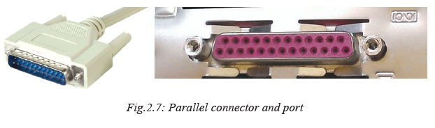
2.3.3.3 Universal Serial Bus
Universal Serial Bus (USB) is an industry standard interface that defines cables, connectors and protocols for connections between computers and peripheral devices. Universal serial bus (USB) is a high-speed serial port that has become the standard interface hence replacing most serial and parallel ports. It is now common to find USB ports on most electronic devices such as tablets, radios, TVs, mobile phones, and set-top boxes. One of the reasons the USB interface has become popular is because as many as 127 devices can be daisy chained and connected to a single port using USB cable such as the one shown in Fig. 2.8.

Activity 2.6: USB Port and Connector
• Explain three reasons why USB interface has replaced parallel and other serial ports on most computers and peripheral devices.
• Move around the computer room and do the following:
1. Find out how many USB ports the computers have.
2. Connect a mouse / keyboard / peripheral device to the computer’s system unit using a USB cable as directed by the teacher. Is the process simple or complicated?2.3.3.4 Personal System/2 ports
Previously, most computers came with a pair of Personal Systems 2 (PS/2) ports also known as mini-DIN. However, most computer manufacturers have phased out PS/2 ports in favour of USB interfaces and wireless connectivity. Fig. 2.9 shows a closer look of the PS/2 ports the one coded in pink to connect a keyboard while the green ports is used connects a mouse.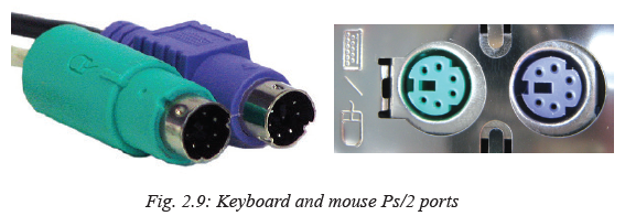
Activity 2.7: PS/2 Port and Connector
In groups, study PS/2 ports on the system unit or use Fig. 2.9(a) to explain the following:
• What colour codes are used to denote the mini-DIN ports for the keyboard and the mouse?
• Check behind your system unit and identify the mini-DIN ports if available. Sketch their appearance.
• What happens if by mistake you connect the keyboard to the mouse port?2.3.3.5 Video graphics array port
A Video Graphics Array (VGA) port is a D-shaped interface used to connect display devices such as TVs, monitor or LCD projectors to the computer. Fig. 2.10 shows an illustration of a 15-pin VGA cable used to connect a monitor or projects to a computer.
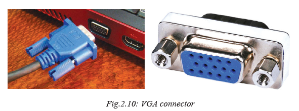
Activity 2.8: VGA Port and Connector
Study the VGA connector shown in Fig. 2.10 or in a computer lab and perform the following tasks:
• Count the number of pins on the VGA cable connector.
• Explain what happens when one of the pins on the VGA connectors happens to be damaged.
• In the computer lab, demonstrate how you would connect a monitor or projector to a VGA port.2.3.3.6 Audio Ports
Most computers and mobile devices come with audio interface used to connect speakers, microphones (mic) and other audio devices. Fig. 2.11(a) shows three audio ports while Fig. 2.11(b) shows output (speaker) and input (microphone) jacks coded in green and pink colours.
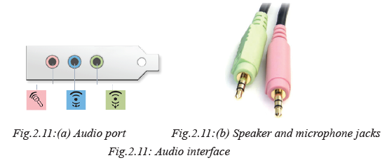
Activity 2.9: Audio Port and Connector
Study the connector (jack) shown in Fig. 2.11(b) and perform the following tasks:
• What colours are used to distiguish between the audio and microphone ports.
• Explain what happens if the two are interchanged by plugging in the audio connector to the mic port and vise versa.
• In the computer lab, demonstrate how you would connect the speakers to audio and mic ports.2.3.3.7 Network port
Network interface is a port that connects a device to physical or wireless transmission media in computer network. Most computers today come with a network interface known as RJ45 shown on Fig. 2.12 (b) to which a transmission media with RJ45 connector shown in Fig. 2.12 (b) is plugged to establish a connection.
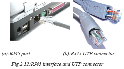
Activity 2.10: Network Interface
Study the RJ 45 connector in Fig.2.12 above or in the computer lab and perform the following tasks:
• Distinguish between network interface adapter and onboard modem.• Apart from Communication Network Riser (CNR) adapter, describe three types of network interface adapters and slots. Which adapter technology is the most current.
• In the computer lab, demonstrate how you would connect computer to local area network using RJ 45 port and connector.2.3.3.8 Firewire connector
Firewire port also referred to as IEEE 1394 is almost similar to USB but has higher data transmission rate. Therefore, firewire is suitable for streaming video from digital cameras to a computer. Fig. 2.13(a) shows an illustration of Firewire port while Fig. 2.13(b) shows the two ends of a firewire cable connectors.

2.3.3.9 High Definition Multimedia Interface
High Definition Multimedia Interface (HMDI) is an interface for transferring compressed and uncompressed digital audio or video data from HDMI-compliant device to a computer, projector, digital TV or audio device. HDMI is intended to be a replacement for analog video standards such as the VGA.
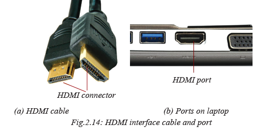
Activity 2.11: HDMI Port and Connector
Study Fig. 2.14 or HDMI interface and carryout the following tasks:
• Identify the devices within the school or at home that comes with HDMI interface.• Draw similarities and difference between the USB and HDMI ports and connectors.
• Through the help of the teacher in the computer lab, demonstrate how you would stream video clips from a video camera to a computer or digital TV through HDMI interface.2.3.3.10 Small Computer Systems Interface
Small Computer Systems Interface (SCSI) is a set of parallel interface standards defined by ANSI for attaching peripheral devices such as printers, disk drives, tape drives and scanners. Although SCSI port shown in Fig. 2.15 is available on some devices, it has become obsolete in favour of USB, Firewire, HDMI and wireless standards.
Activity 2.12: Connecting Peripheral Devices
1. In groups of two or three, check whether your computer has an SCSI interface and perform the following tasks:
• Research on ANSI standardization body and trace the evolution of SCSI interface, number of devices supported, and related viariations.
• Identify devices within the school or at home that comes with HDMI interface.
• Draw similarities and difference between the SCSI and parallel LPT1 ports and connectors.
2. Adan intends to start computer bureau services such as printing and cyber cafe in Kigali. Assuming Adan has come to seek advice on specifications to consider before purchasing computers:
• Use demonstration or illustration to help Adan differentiate between desktop and tower type system unit.
• Take Adan through the ports at the back of the system unit explaining to him the purpose of each.
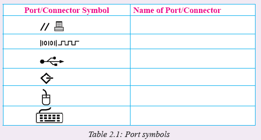
• Demonstrate and help Adan connect basic peripheral devices such as monitor, keyboard, mouse and printer to the right ports.3. To easily identify each of the ports and connectors, device manufacturers use symbolic colour codes and impressions. For example, Table 2.1 a list of symbolic representations of some of the ports discussed in this section. Identify and explain what port or connector each symbol stands for.
2.4 Internal Computer Components
We have already learnt about various peripheral devices and how they are connected to the system unit through ports. In this section, we discuss the main components found inside the system unit such as disk drives, motherboard, processor and memory. But, before we open the system unit cover, it is important that you observe the following safety precautions:
1. Always disconnect the computer from power source before starting to work on them.
2. Do not work on any peripheral device without the guidance of the tutor or laboratory technician.
3. Never work in isolation because you may need help in case of any emergency.
4. Always discharge static electricity that might have built up on the body by touching an earthed metallic object or wearing antistatic wrist member.Activity 2.13: Internal Computer Components
1. Through the guidance of your teacher or lab technician, work in groups of two or three to open the system unit cover to expose the internal components as shown in Fig. 2.16.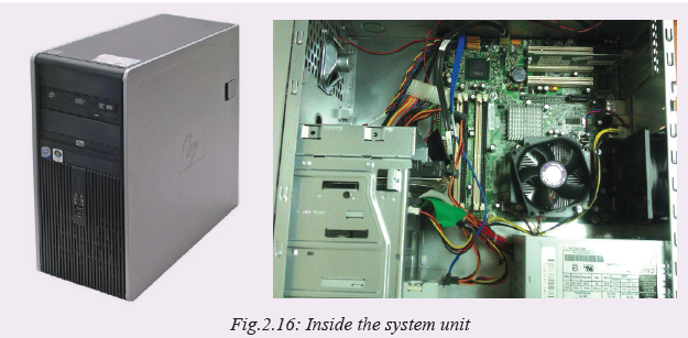
2. Observe and identify various components inside the system unit.
2.4.1 Power supply unit and connectors
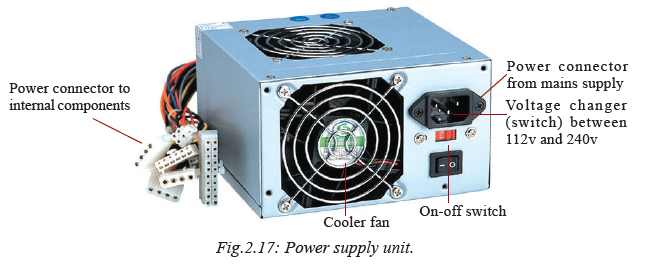
The Power Supply Unit (PSU) shown in Fig. 2.17 converts alternating current (AC) from mains to direct current (DC) required by internal computer components. The current supplied to the internal components like motherboard, hard disk, and optical drives depends on the rating from the device manufacturer. Note that unlike desktop computers that are fitted with PSU, portable computers like laptops come with power adapters that convert AC to DC.
Types of power supply unit connectors
The power supply unit connectors can be classified into external and internal connectors. The external connectors are used to connect the power supply unit to the power outlet while internal connectors are used to supply and distribute power to internal devices inside the computer found inside a computer case. In the power supply unit shown in Fig. 2.17 above shows an examples of internal and external power connectors.
2.4.2 Motherboard
A motherboard shown in (Fig. 2.18) is the main printed circuit board onto which all components of the computer interconnect or are mounted and communicate with each other.

The following are the main components that are attached or mounted on the
motherboard. They are discussed later in the section:
1. Central Processing Unit (CPU): it is also called the microprocessor
2. Computer memory: They are various types of read only memory chips (ROMs) and random access memory modules (RAM).
3. Disk drives: hard disk drive and the optical disk drive.
4. Adapter cards: they add functionality to the computer e.g. network interface cards, TV/Radio cards, wireless network cards etc.2.4.3 Central processing unit (CPU)
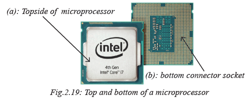
The Central Processing Unit (CPU), also known as the processor, is the most important component of the computer. It is actually regarded as the “brain” of the computer because all processing activities are carried out inside the processor. In microcomputers, the CPU is housed inside the system unit. The CPU is mounted on a circuit board known as the motherboard or the system board. For ease of upgrade, most motherboards have a socket into which the contact pins shown in Fig 2.19 (b) are aligned to and inserted.
Activity 2.14: Central processing unit(CPU)
Using Fig. 2.21 (a) and (b), identify the type of microprocessor, and socket on the motherboard of your computer. The CPU is made up of three distinct components within it:
1. The Arithmetic Logic Unit (ALU): performs all arithmetic and logical operations.
2. Control Unit: interprets instructions and controls speed of execution using a clock.
3. Registers: special memories within the CPU for holding instructions and data.Role of the CPU
The CPU consists of three functional elements namely the Control Unit (CU), Arithmetic and Logic Unit (ALU). Figure 2.20 illustrates the functional elements of the CPU.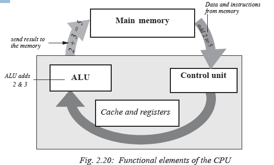
The control unit
The control unit coordinates all processing activities in the CPU as well as input, storage and output operations. It determines which operation or instruction is to be executed next. To coordinate these activities, the control unit uses a system clock. When the clock ticks, a task is ashered into the CPU for processing. When it ticks again, the task is ashered in/out of the CPU. Different tasks require different number of clock ticks (time lengths) in order for them to be fully processed.
The system clock sends electric signals as its means of communication to the CPU.
The number of pulses per second determines the speed of a microprocessor. The faster
the clock pulses, the faster the CPU, hence the faster the computer can process data.Arithmetic and logic unit (ALU)
Activity 2.15:
Group work: In groups of five, do the following:
1. Choose one of you to be the group leader. By consensus, select two lucky numbers for the group (any two numbers between 1 and 50). Assuming you select 9 and 18. The group leader assigns each member at least one of the following tasks at the same time:
Task A: 9 + 18 =
Task B: 18 – 9 =
Task C: 18 x 9 =
Task D: 18 ÷ 9 =
2. Let each of you provide an answer to the group. Compare your answers. What is the general name given to these operations?The arithmetic and logic unit is the location within which all arithmetic and logical
operations are carried out in the CPU. Basic arithmetic operations include; addition,
subtraction, multiplication and division.Logic operations are based on the computer’s capacity to compare two or more
values. For example, it may compare whether a piece of data is greater than or less
than, equal to or not equal to etc.In order for the ALU to be able to process data, it has special temporary storage locations called registers, which hold the data just before processing. Registers also hold the results after processing.
2.4.4 Computer memory
(a) Main/primary memoryActivity 2.16
Imagine yourself walking in a forest. You keep on seeing different types of trees as
you proceed along. Halfway through the forest, you meet a forest guard who shakes
your hand and asks you what you are doing in the forest. In groups of three, discuss
the following:
(i) When you reach the edge of the forest, are you likely to remember all the trees you
saw in the forest? Why?
(ii) Which tree are you likely to remember and why?NB: Discuss this in reference to short term memory and long term memory in human
beings. Present your views to the class.Human beings have memory, both short term and long term, where they keep information. Daily unimportant information is usually kept in the short term memory then discarded after a while. Important information is usually stored in the long term memory. It can be remembered even after many years. Computer memory is modelled along the same lines.
Activity 2.17
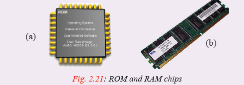
In S1, you were introduced to computer memory. In pairs, study the pictures in Figure 2.21. What do you think the acronym ROM stands for? What about RAM?
(a) Which one is temporary memory? Which one is permanent?
(b) Access the content provided by the teacher and research about the various types
of ROM and RAM, their advantages and disadvantages.
(c) Make a presentation in class as requested by the teacher.Main memory also known as primary storage is a type of storage that is directly accessible by the processor. Computer memory can be classified into Read Only Memory (ROM) and Random Access Memory (RAM). Figures 2.9 (a) and (b) show a ROM chip and RAM module respectively.
Read Only Memory (ROM)
Read Only Memory is used to store programmed instructions and data permanently or semi-permanently. Data and instructions stored in ROM are those which remain unchanged for long periods of time e.g. POST instructions, special purpose computers, computerised fuel pumps instructions etc. Depending on permanence of the instructions or data written on it, there are four
Types of Read Only Memory namely:
(i) Mask Read Only Memory (MROM): Once the content is written on it by the manufacturer, it cannot be changed. Examples of computer that use MROM based operating systems are those that require long term sustainability e.g. computers that run network operating systems or server operating systems.(ii) Programmable Read Only Memory (PROM): This allows the user to alter it only once after the content is written on it. Examples are the PROM compact disc and PROM intergrated circuit chips.
(iii) Erasable Programmable Read Only Memory (EPROM): This has a transparent quartz window through which its contents, can be erased by exposing it to ultra violet (UV) light, and then reprogrammed for another use.
(iv) Electrically Erasable Programmable Read Only Memory (EEPROM): This type of ROM can be erased and reprogrammed using electricity. An example of EEPROM is the memory that stores the basic input/output system (BIOS).
Characteristics of Read Only Memory (ROM) are:
1. One can only read its content but you cannot write on it unless it is a special type of ROM.
2. It is non-volatile i.e. its content is not lost when the computer is switched off.
3. Stores permanent or semipermanent instructions from the manufacturer called firmware. It can store semipermanent instructions because some variations of ROM chips can be programmed according to the user’s specification.Random Access Memory (RAM)
Random access memory (RAM) also known as working storage is used to hold instructions and data needed by the currently running applications. The information in RAM is continually read, changed, and removed. It is referred to as random access because its content can be read directly regardless of the sequence in which it was stored.
As opposed to ROM, the content in RAM is held temporarily and its content is lost once the computer is turned off. Therefore, before switching off the computer, it is important that one stores (saves) his/her work in a device that offers relatively permanent storage facility.
Characteristics of Random Access Memory (RAM) are:
1. Data can be read (retrieved) and written (stored) in it.
2. RAM is a temporary (volatile) storage because its content disappears when the computer is switched off.3. Its content is user defined i.e. the user dictates what is to be contained in the RAM.
The two main types of RAM are:Static RAM
Static RAM (SRAM) is a fast type of memory mostly located inside a microprocessor. For this reason, SRAM is used on special purpose memories such as cache memory. Cache memory is used to enhance the processing speed by holding data and instructions that are instantly required by the processor.Dynamic RAM
Dynamic RAM (DRAM) is a relatively slower type of RAM compared to SRAM. The term dynamic refers to the tendency for the stored charge to leak away, even with constant power supply. For this reason, DRAM requires periodic recharging (refresh) to maintain its data storage. Fig. 2.22 shows ROM and RAM on the motherboard.
Special purpose memories
Some minute types of memories are included inside a microprocessor or input/output devices, in order to enhance its performance. These memories include buffers, registers and cache memory as discussed earlier.Cache memory
Activity 2.18
Group work:
In groups of five, take the mobile phone that has been provided by the teacher. Scroll
through the following:
1. The Contacts lists.
2. The Recently called list.Why do you think you need to have a recently called list? Discuss the importance of
this list and present the finding to the class.Cache memory (pronounced as cash) is the fastest type of RAM. Its main aim is to store data that has been recently accessed by the processor. The belief is that the same data may most likely be required again soon. This would save the time of having to retrieve it from the slow secondary memory. This arrangement enhances overall computer performance by avoiding the slow secondary storage for recently used data. The only time data is retrieved from secondary storage is when no copy is in catche.
There are three types of cache memory namely:
• Level 1: also known as primary cache located inside the microprocessor;
• Level 2: also known as external cache that may be inside the microprocessor or mounted on the motherboard, and
• Level 3: is the latest type of cache that works with L2 cache to optimise system performanceBuffers
Activity 2.19
Brainstorming:
Study the picture of a dam provided by the teacher. Search for other pictures of dams on the internet. List down their names.
As a class, brainstorm on the driving forces that motivate construction of dams along rivers? Buffers are special memories that are found in input/output devices. Input data is held in the input buffer before being forwarded to the memory to avoid overloading the memory. The data can then be transferred to the memory at a reasonable pace to avoid flooding it.Output buffers play a similar role when sending data to the network or output device.
For example, printers have buffers where they can store massive documents sent by the
CPU for printing hence freeing the CPU to perform other urgent tasks as the printer
continues to print in the background. Buffers therefore play a controlling role between
devices to avoid a quick device flooding a slow device with data or instructions.Registers
Activity 2.20
Pair Work:
Most organisations have a waiting room where guests rest as they wait to see the company boss in turns.Discuss why such an arrangement is important. What is likely to occur if there is no
such arrangement for a busy office.As opposed to buffers, registers hold one piece of data at a time and are inside the CPU. Just like the secretary in Activity 2.16 who hosts and clears the next one person just before he/she sees the boss, registers hold that one data item just before or after processing within the CPU.
Examples of registers are:
Accumulator: This temporarily holds the results of the last processing step of the ALU.
Instruction register: This temporarily holds an instruction just before it is interpreted
into a form that CPU can understand.
Address register: This temporarily holds the next piece of data waiting to be processed.
Storage register: This temporarily holds a piece of data that is on its way to and from the CPU and the main memory.(b) Secondary memory
Activity 2.21
Research on the internet about secondary/tertiary memory. Is it temporary or permanent? Which devices are referred to as secondary/tertiary storage devices?
Why are some of these devices referred to as mass storage devices?Secondary storage, also referred to as auxiliary storage, are devices that provide alternative long-term storage for programs, data and information. Because of their large capacity they also referred to as mass storage devices. They are regarded as secondary because unlike primary storage, they are not directly accessible by the CPU. Secondary storage devices can be classified according to:
(a) Portability: removable and fixed
(b) Technology used to store and retrieve data: magnetic, optical, magneto-optical and solid state.In this section, we discuss these devices by indicating whether a device or media is removable and the technology used to store data on it.
Removable storage
Removable storage media are those that are not housed inside the computer. Data is read and written into the media using a device known as drive. Examples of removable storage include optical disks (e.g. CD’s, VCD’s and DVD’s) and solid state devices (e.g. Flash disks). Others include the floppy diskettes, magnetic tapes and magnetic disks which have become virtually obsolete in the personal computing space.Optical storage media
Activity 2.22
Study the pictures in Figure 2.23. Have you seen them before in real life?
(a) State three areas where you have witnessed the disks being used.
(b) Using a ruler, measure the diameter of each and note down. Investigate on the internet about the diameters of such disks.
(c) What advantages do you think they offer to the user?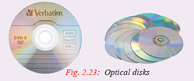
Optical storage media are so called because data is written and read from them using a laser beam. A laser beam is a very strong concentrated light. Two reasons why optical storage media are used:
1. They store very large volumes of data.
2. Data stored in them is more stable and more permanent than the magnetic media.Compact disks (CD)
Compact disks hold large quantities of data and information. One disk can hold as much as 700MB. They are mostly used to store data and information that requires a lot of space such as video clips, software, sounds etc. Currently compact disks are available in three forms namely:
Compact disk-read only memory (CD-ROM): Compact disk read only memory (CDROM)
as the name suggests contain data that can only be read but cannot be written on. To record data the recording surface is made into pits and lands (bumps). When a laser beam fall on the land,this is interpreted as 1, otherwise a zero is recorded.Compact disk-recordable (CD-R): Compact disk recordable (CD-R) are coated with special dye which changes colour to represent data when burned using a laser beam. Once data is burned on a CD-R, it becomes read only.
NB: CD-ROMs and CD-Rs are referred to as Write Once Read Many (WORM.) Data is only recorded once but can be read as many times as possible. Compact disk-rewritable (CD-RW): Unlike the CD-Rs, these types of compact disks allows the user to record, erase and rewrite new information just as one would with floppy disks.
Digital versatile disks
Digital Versatile Disk (DVD), also known as digital video disk resembles a compact disks in every aspect. The only difference is that they have a higher storage capacity over 17 Gigabytes of data. Figures 2.23 (seen earlier) shows various examples of optical disks.Optical card
An optical card stores data and is read optically on a stripe rather than using magnetic ink. These types of cards are mostly used in banking and other business organisations to record customer details. Figures 2.24 below shows examples of an MICR reader reading a cheque and an optical card in the optical card reader.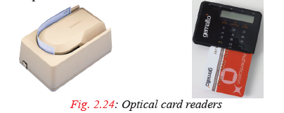
Solid state storage media
Activity 2.23
Study the pictures in Figure 2.25. What do you think they represent? Also compare them with the samples provided by the teacher. Where in real life have you used or seen people using these components? What are the names of these components?
Solid state storage is a non-volatile storage that makes use of integrated circuits
rather than mechanical, magnetic or optical technology. They are referred to as solid state because they do not have movable parts. Some examples of solid state devices are memory sticks (Figure 2.13 (b) and (c)) and flash disk drives (Figure 2.13(a)).Non-removable/fixed storage media
The hard disk and its structure
Activity 2.24
Access the website provided by the teacher and read about the hard disk of a computer.
(a) Search for pictures of the hard disk on the internet in order to learn about its structure.
(b) How does it store data? What are tracks, sectors and platters?
(c) Make a brief presentation to the class concerning your findings.
The hard disk is a secondary storage device that stores data and programs installed in
a computer for a long time (permanently) even after the computer has been switched
off. The data includes any created documents and downloaded such as text, photos
and music. When the computer requires to process data and instructions stored on the
hard disk, the it has to be fetched first and placed in primary memory (RAM). When
the data and instructions are in RAM, they can be easily fetched into the cache then
the registers as directed by the control unit of the CPU.Traditionally, the hard disk is mounted inside the computer. For this reason we refer to it as a fixed disk. However, this is not always the case because some hard disks
are removable.
The hard disk is made up of metallic disk platters together with a read/write head,
housed in a protective metal case (Figure 2.26(a)).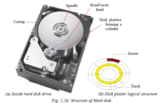
The one or more metallic platters, stacked on top of each other but not touching one another. The stack of platters is attached to a rotating pole called a spindle. If it has more than one platter, they are stacked on top of each other to form a cylinder. A cylinder requires multiple read/write heads, one for each platter.
The read/write head floats just above the surface of the rapidly rotating disk to read or write data. On the surface of each disk are special read/write circular regions called tracks (Figure 2.26 (b)). Each track is divided into angular sections called sectors similar to the sector of a circle.
Most computer hard disks are connected to the motherboard via channel called controllers. Some of these controllers are Integrated Drive electronic (IDE), enhanced
IDE or AT attachment (ATA).Disk drives
A disk drive is hardware device in or attached to a computer that reads the data stored on a disk and writes data onto the disk for storage. Drives are mounted in drive bays in the system unit chassis. Examples of disk drivers inside the systems unit include optical (CD/DVD) drives, hard disk drives and tape drives. Figure 2.27(a) shows an illustration of hard disk drive mounted in the system unit while Fig 2.27(b) shows a CD/DVD drive on a Laptop.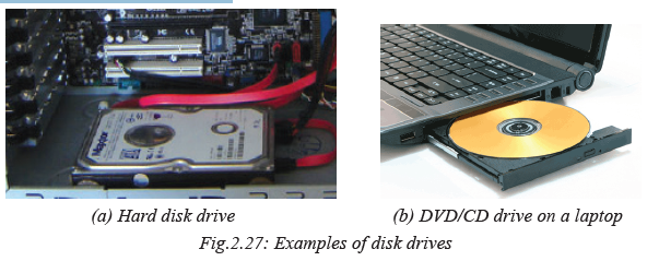
2.4.5 Adapter card
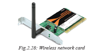
Adapter card or add-on card is a circuit board used to increase functionality of a computer e.g. adding a TV receiver, and wireless network etc. Fig. 2.28 shows a wireless network card. It enables the computer to connect to a Wi-Fi hotspot.
2.4.6 Elements attached to the motherboard
As mentioned earlier, some of the basic elements attached to the motherboard include CPU Socket, RAM slots, silicon chips, BIOS, expansion slots, CMOS battery, and controllers and electronic data buses.
• CPU Socket: The CPU or processor socket is the connector that houses the CPU to establish mechanical and electrical contact between the processor and the motherboard. Some sockets uses Pin Grid Array (PGA) that consists of holes where pins on the underside of the processor connects
• RAM slots: The RAM slots or sockets located near the processor are connectors
that establish contact between memory modules and the motherboard. Depending on the type of motherboard, there may be 2-4 RAM slots (banks) that determine the amount of memory that can be installed.
• Chipset: Normally a chipset is an element that facilitates intercommunication between the microprocessor to the rest of the components on the motherboard.
• Expansion slot: Alternatively referred to as bus slot or port is a connection on the motherboard to which an expansion card can be plugged in order to expand the capability of a computer.
• CMOS battery: Complementary metal-oxide semiconductor (CMOS) is a small amount of memory on a computer motherboard used to store BIOS settings. To avoid losing the settings, CMOS is powered by a button-like cell referred to as CMOS battery.
• Data buses: if you carefully observe the surface of a motherboard, you will see printed electronic pathways or lines between components. These pathways are referred to as data buses because they are used to transfer data and instructions between components inside the computer.Assessment Exercise 2.1
1. Distinguish between the following:
(a) AC and DC power supply.
(b) Bluetooth and infrared connectivity.
(c) Firewire and USB ports.
(d) 5-pin DIN and PS/2 ports.
2. Explain three types of serial ports available on a typical desktop computer.
3. State two advantages of USB port over the parallel port.
4. Explain how you would connect both data projector and monitor to a single computer.2.5 Assembling desktop computers
With the knowledge and skill in handling internal and external components of a desktop computer, it’s now time to roll-up your sleeves to assemble and disassemble a computer. However, before you proceed, remember to observe safety precautions in order to avoid health injuries or damages to delicate computer components. Let’s start by having a look at tools that you may need to assemble or dis-assemble a computer.Activity 2.25: Assembling a computer
Looking at a toolkit in the computer lab or illustration shown in Fig. 2.29 identify the following tools:
1. Extended extractor: also called a part grabber are, used for retrieving dropped objects, such as jumpers or screws, from inside the computer.
2. Antistatic wrist member.
3. Torx screw drivers of varying sizes.
4. Multimeters used to measure the resistance, voltage, and/or current within computer components.
2.5.1 Step 1: Mounting Hard disk drives
Hard disk drives are usually mounted on the system unit case and connected to the motherboard through either Enhanced Integrated Drive Electronics (EIDE), Small Computer System Interface (SCSI) or Serial Advanced Technology Attachment (SATA) cable interface. SATA is one of the latest technologies. It supports hotswapping i.e. a drive can be detached or attached to the motherboard while the computer is ON. Fig. 2.30 illustrates how to mount a SATA hard disk drive.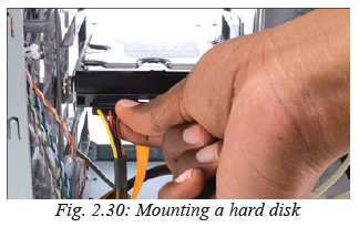
Activity 2.26: Mounting a Hard Disk
In groups or individually, follow the guidelines below to mount a hard disk drive:
1. Determine whether the motherboard has an empty SATA controller socket.
2. Slide the hard drive into the available bay on the system unit casing and secure it firmly by screwing or using the restraining mechanism provided by the manufacturer.
3. Plug in the SATA interface cable to the drive and to motherboard SATA/IDE controller.
4. Connect the power cable from the power supply unit to the back of the hard drive as shown in Fig. 2.30.2.5.2 Step 2: Installing optical drives
Optical drives such as CD and DVD drives are attached and detached from the sytem unit in the same way as hard disk drives.
Activity 2.27: Installing optical drives
In groups or individually, follow the guidelines below to mount an optical drive:
1. Determine whether the motherboard has an empty SATA or EIDE controller socket.
2. Slide the optical drive into available bay on the system unit casing and secure it firmly by screwing or using the restraining mechanism provided by the manufacturer.
3. Plug in the SATA or EIDE interface cable to the back of the drive and motherboard controller.
4. Connect a power cable from the power supply unit to the back of the optical drive
similar to procedure used to insert power at the back of hard disk drive.2.5.3 Step 3: Mounting power supply unit
To replace a damaged Power Supply Unit proceed as follows:
1. Turn off the power and remove the power cable from the socket, and then unscrew
the faulty power supply unit.
2. Unplug power cables connected from the power supply unit to internal drives
and P1 on the motherboard, and then remove the faulty unit.
3. Insert a new power supply unit and fasten the screws that hold the power supply
onto the chassis. Connect P1 from the power supply unit to the motherboard.
5. Connect power supply cables from the unit to other internal components such as disk drives.2.5.4 Step 4: Mounting motherboard
There are several types of motherboards ranging from the outdated Advanced Technology (AT) and Advanced Technology Extended (ATX) to the current.Fig. 2.31 shows an illustration on how to mount a motherboard.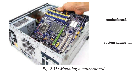
Activity 2.28: Mounting a motherboard
In groups of two or three, demonstrate how to mount a motherboard using the following guidelines:
• Line it up properly on the chassis, screw and fit it into place.
• Mount the processor, RAM modules and any expansion cards separately.
• Plug in the power cable denoted with P1 connector from the power supply unit.
• Connect other internal components onto the board, and then connect the monitor, keyboard and mouse to the system unit.
• Test for power and ensure that internal and external components are initializing correctly during POST.2.5.5 Step 5: Installing computer memory
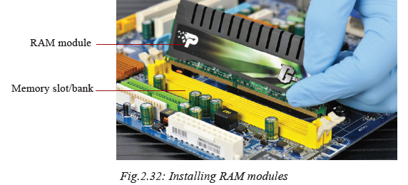
Fig. 2.32 shows how to install a RAM module. Open the clips, align the module with the slot then press into position until the clips hold tight.
Activity 2.29: Installing a computer memory
Before you attach or detach a memory (RAM) module, you need to make some considerations. In class, discuss such considerations e.g. motherboard architecture,
number of memory banks available, type and speed of the processor, and maximum
memory capacity.
Through the guidance of the teacher, install a RAM module using the following
guidelines:
1. Discharge any static charges before touching the module.
2. Place the module upright in the slot so that the notches on the module are lined
up with the tabs on the memory slot.
3. Gently press down on the module. The retention clips on the side should be raised
to the locked position. You might need to guide them into place with your fingers.NB: Once mounted, the new memory module is automatically detected during bootup
and its capacity calculated. However, if not properly inserted, the computer makes
a continuous beeping sound.2.5.6 Step 6: Replacing CMOS battery
Computers have a Complementary Metal-Oxide Semiconductor (CMOS) battery that
powers the BIOS chipset to ensure basic settings such as date and time are up-to-date.Activity 2.30: CMOS Battery Replacement
Study the motherboard and perform the following tasks:
1. Identify the CMOS cell battery mounted on the motherboard as shown in Fig. 2.33.
• Install the new battery so that the bottom is in contact with the motherboard.
• Restart the computer and press the key or combination of keys to enter BIOS
setup.
• To restore the settings, use the BIOS setup menu. Alternatively, use automatic
configuration options.2.5.7 Step 7: Upgrading BIOS
Basic Input Output System (BIOS) is a firmware that stores Power On-Self Test instructions that are required to boot-up a computer. BIOS can be upgraded to support new devices in the market. The old one is flashed a new one installed from a suitable BIO manufacturer such as Phoenix.Activity 2.31: BIOS upgrade
Follow the teachers guidance to update and upgrade BIOS ROM:
1. Identify the manufacturer of the BIOS chip.
2. Back up the CMOS Settings and restart the computer using a combination of CTRL + ALT + DELETE keys.
3. Enter the CMOS settings program using the specified key or combination of keys, and then write down the settings.
4. Backup the old BIOS in case the upgrade results to system failure.
5. Insert the manufacturer’s BIOS utility disk. The disk contains a program that
automatically flashes the BIOS.
6. Restart the computer. If successfully done, the BIOS retains the new firmware.2.5.8 Step 8: Mounting adapter card
There are several types of adapter cards. These include Industry Standard Architecture
(ISA), Extended ISA (EISA), Peripheral Component Interconnect (PCI), Accelerated Graphics Ports (AGP), Video Electronics Standards Association (VESA), Audio Modem Riser (AMR) and Communication Network Riser (CNR).Activity 2.32: Adapter Card
1. Using reliable internet sites or reference materials, discuss the architecture of each type of the adapter cards highlighted above.
2. Study the adapter card shown in Fig. 2.34 and describe its function.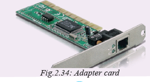
3. Through the guidance of the teacher, mount an adapter card using the following guidelines:
(a) Turn the computer off and ensure that you carry out proper ESD procedures.
(b) Position the controller card upright over the appropriate expansion slot.
(c) Place your thumbs along the top edge of the card and push straight down.
(d) Secure the card to the chassis using the existing screw holes.2.5.9 Step 9: Mounting a microprocessor
Like other computer components that become obsolete with time, you may find it more cost-effective to upgrade the processor than buying a new computer. Before purchasing or installing a new processor, make sure it is compatible with the motherboard. For example, you cannot install an AMD processor in an Intel motherboard and again not all processors from the same manufacturer uses the same socket.Activity 2.33: Installing a Microprocessor
In groups or individually, mount a microprocessor onto a motherboard using the
following guidelines:
1. Ensure that the lever is raised up perpendicularly.
2. Gently place the processor in the socket but do not push, as shown in Fig. 2.35.
3. Lower the lever to grip the CPU into place.
4. Connect the processor fan to the motherboard.
2.6 Replacing a laptop battery
No matter how well you treat your laptop’s battery, it will eventually degrade and die. When the battery weakens, Microsoft Windows gives warning like “consider replacing your battery” or adding a red X on the battery icon. This is the time to replace the battery to avoid disappointments!Activity 2.34: Laptop Battery Replacement
In groups or individually, remove and replace a worn-out laptop battery using the
following guidelines:
1. Press the battery release button or unscrew the cover.
2. Remove the battery compartment’s cover.
3. Slide the wornout battery out, and then insert the new one.2.7 Upgrading laptop memory
Like in desktop computers, it is possible to upgrade or replace a RAM module of
a notebook PC. Unlike the desktop PC RAM module, notebook PC RAM module
such as Small Outline DIMM (SoDIMM) are small in size.Activity 2.35: laptop memory Upgrade
To upgrade laptop memory proceed as follows:
1. Open the computer’s case or memory compartment cover.
2. Insert the RAM module into an available slot at an inclined angle as shown in Figure 2.36.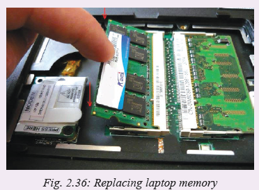
2.8 Disassembling desktop computer
Disassembling a computer mean detaching external and internal components from the system unit. This process involves unplugging, unscrewing and sliding out components depending on mechanism used to connect to the system unit or mount it onto motherboard. To disassemble a desktop computer, proceed as follows:
1. Disconnect the computer from the source of power by unplugging the power cable from power supply unit.
2. Unplug peripheral devices attached to the system unit such as monitor, keyboard, mouse and printer.3. Open the outer cover on the system unit by unscrewing or sliding it out. Some
desktop computers have large knobs you can remove by hand to open the system
unit cover.
4. Remove the adapter cards by first unscrewing it on the cases, and then gently
unplug it off the motherboard as shown in Fig. 2.37.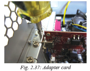
5. Remove the fixed drives such as hard disk and optical (CD/DVD) drives by unscrewing and disconnecting them from power supply unit. Next, disconnect the IDE or SATA interface cable that connects the drive to the motherboard.
6. Remove memory (RAM) modules by pressing the tabs located on both ends down away from the memory slot. The module will lift slightly. Carefully hold the module by the edges and to remove it from the motherboard.
7. Remove the power supply unit starting with power connector to motherboard, CPU fan cabinet fan, power buttons and drives if any. Next, unscrew the unit to unmount it from the system casing
8. Remove the CPU and its fan by first unscrewing the cooler fan from the motherboard. You unlock the processor from the socket by lifting the level as shown in Fig. 2.38.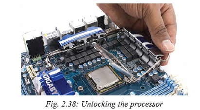
9. Finally, unscrew the motherboard to unplug it from the system unit casing. This leaves you with an empty shell of the casing.
Assessment Exercise 2.2
1. Differentiate between the following:
(a) EIDE and SATA hard disk drive.
(b) Baby AT and ATX motherboard.
(c) PGA and SECC processors.
(d) AMR and CNR expansion cards.
2. Explain why it is important to use the right tool for the right purpose when repairing, upgrading or assembling a desktop PC.
3. List some of the common tools available in a computer maintenance toolkit.
4. Explain five types of expansion cards used on desktop computers.
5. Outline the procedures you would follow to install the following:
(a) PGA2 processor.
(b) DDR2 RAM module.
(c) CNR modem add-on card.
6. You have just installed a new power supply, but the computer doesn’t seem to be
getting any power. What might be the problem?
7. You want to upgrade your BIOS by “flashing” it. Outline the procedure you should follow.
8. Explain how you would perform the following operations:
(a) Replace a faulty notebook PC battery.
(b) Upgrade laptop memory.
(c) Add a PC card.Activity 2.36: Assembling a desktop computer
University of Rwanda College of Science and Technology (URCST) has started a project aimed at assembling state of art desktop computers. As a member of the team, you are required to identify the components required to assemble a desktop computer.
1. Demonstrate step by step how to assemble a PC starting with the
following internal components:
• Motherboard
• Processor
• RAM
• Hard disk drives
2. Assuming you are using a single EIDE controller to mount two CD-ROM/DVD drives, explain how you would configure the two drives.
3. One of the clients makes a call informing you that one of the computers she bought consistently loses its date/time settings. Outline the procedure you would follow to solve the problem.2.9 Cleaning and disposal of computer components
Regular cleaning and proper disposal of computer components is a proactive environmental and social practice that helps in mitigating health and environmental problems.2.9.1 Cleaning using liquids
Before using a liquid cleaner, make sure that the computer or device is off and completely dry. Before cleaning a computer, take note of loose components or connections and tighten them up.Activity 2.37: Cleaning computer devices
1. Highlight three benefits of cleaning a computer and peripheral devices regularly.
2. Using mild, soapy water and lint-free cloth, wipe off dusty components such as keyboard, mouse, system unit and monitor. For devices that are damaged by water, make use of chemical or alcohol solvents. Note that some chemical solvents may be hazardous to humans and the environment hence they should be handled with care.2.9.2 Blowing dust and debris
Dust can cause electrostatic discharge leading to overheating of components inside the computer while debris may affect the mechanical parts. To remove debris, a blower shown in Fig. 2.39 uses compressed air to remove such debris dust in system unit, keyboard, expansion slots and ports
Activity 2.38: Blowing Dust and Debris
1. To remove dust and debris in the system unit, use a blower or hand-held vacuum cleaner.
2. Using a hand-held vacuum cleaner, carefully clean inside the computer making sure you do not damage delicate components.2.9.3: Replacing printer cartridges
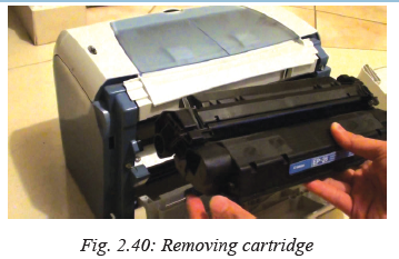
Although there are various types of printers and associated models, we follow the same basic steps to replace ink or toner cartridges. In this section, we outline general procedure for replacing ink or toner cartridge regardless of printer type and model.1. Turn on your printer and open the lid/flap that encloses the cartridges and then remove the cartridge or cartridges you want to replace as shown in Fig. 2.40.
2. Take note of the cartridge model number and type. This is the number that you use to purchase new cartridge. If you are unsure of the number, take the cartridge as sample to a vendor for help.
3. Once you purchase a new cartridge, remove the protective sticker covers, strap and sticker before installing the cartridge such as shown in Fig. 2.41.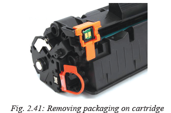
4. Gently insert the cartridge into the printer. Note that most cartridges easily lock
into place with a little pressure.
5. Once you install the cartridge(s), connect the printer to the computer, and print a test page to make sure that the cartridges have been installed correctly. You may be required to reconfigure printer heads for best quality.Activity 2.39: Safety Precautions
1. In the class, discuss how the government clean-up activities in Rwanda has helped in dealing with disposal of computer parts, cartridges and plastic bags that come with some computer components.
2. Explain health and environment dangers that may occur due to improper disposal of laptop or mobile phone batteries containing lithium, mercury, or nickelcadmium.Assessment Exercise 2.3
1. A customer is complaining that the power in the office sometimes surges, some times causes blackouts and has EMI. What single device should you recommend to help the most in this situation?
2. A printer in the college office has recently started experiencing paper jams. They seem to be occurring quite frequently. Explain the probable causes.
3. A printer is producing garbled printouts with characters that don’t make any sense. Identify the likely cause.
4. State two components that are most likely to be replaced in a laser printer
5. Explain why it is important to regularly blow out dust from a c omputer.
6. State the cleaning solution to CD/DVD drive, keyboard and monitorUnit Test 2
1. Write the following abbreviations in full as used in computer systems:
(a) USB (b) SCSI (c) IDE
2. Explain the following features:
(a) PGA2 socket (b) Local buses
(c) Cache memory (d) Memory banks
3. Explain four types of ports available on a computer giving one example of a device connected to each.
4. Differentiate between CRT and LCD monitors giving two advantages of each.
5. A customer is planning to buy a computer and has approached you for advice. The customer wants to use the computer for digital video editing. Explain six hardware requirements the customer should consider.
6. You have decided to upgrade the processor and memory capacity of a computer from duo core 1.7 GHz with 256 MB of RAM to i7 processor and 4GB of RAM. Outline the steps you would follow.
7. Outline the procedure you would follow to replace a power supply unit.
8. Your computer has three hard drives installed; two on the primary controller and one on the secondary controller. You are planning to install a fourth drive without changing the designations of the existing drives. Outline the procedure you would
follow to install and configure two IDE drives such as a hard disk and a CD drive on a single Hard Disk Controller.
9. A customer has complained about a problem in playing audio music though the media player shows that the music is playing. Describe the steps you would follow
to troubleshoot the problem.
10. Explain the importance of preventive maintenance, highlighting some routine maintenance practices that need to be carried out in a computer laboratory.