UNIT 5 APPLICATIONS OF OPTICAL FIBER IN TELECOMMUNICATION SYSTEMS.
Key unit competence: Differentiate optical fiber transmission and other
transmitting systems.
My goals
• Explain the functioning of optical fiber
• Explain attenuation in optical fiber
• Identify and explain the components of optical fiber system
• Solve problem related to attenuation giving answers in decibels
• Describe telecommunication system
• Describe functions of amplifiers in optical fiber transmission
• Distinguish optical fiber and other telecommunication systems
INTRODUCTORY ACTIVITY
Investigating the use of optical fiber in RWANDA
Rwanda plans to connect three million people to the World Wide Web as
part of the “Internet for All” project. The project is a World Economic Forum
initiative that aims to connect 25 million new Internet users in Kenya,
Uganda, South Sudan and Rwanda by 2019.
This goal will partly be achieved by addressing the challenges of affordability,
digital skills gap, lack of local content and limited infrastructure, which are
hindering growth in the use of Internet across the region (http://www.threastafrican.co.ke, 2017)
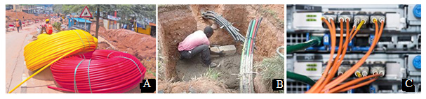
Fig.5. 1: The installation and use of optical fiber in Rwanda
1. Observe the images A, B and C (Fig.5.1) and describe what you can see.
2. What are the uses of optical fiber in transmission of signals?
3. How do optical fibers function? In which field?
4. Discuss other applications of optical fibers.
5.1 PRINCIPLES OF OPERATIONS OF OPTICAL FIBERSACTIVITY 5.1: Total internal reflection in optical fiber.
Fig.5. 2: The total internal reflection in the optical fiber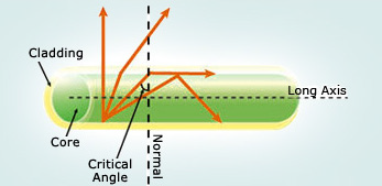
Given the illustration above (Fig.5.2), one can see different rays insidethe optical fiber.
As the angle of incidence in the core increases, as the angle of refraction
increases more until it becomes right angle at a certain value of incidence
angle called critical angle. Discuss:
1. What do you understand by the term critical angle?
2. What causes the total internal reflection?
3. Discuss different fields where total internal reflection can be useful.
5.1.1 Definition
An optical fiber (fiber optics) is a medium for carrying information from one
point to another in the form of light. It uses a flexible, transparent fiber made
by drawing glass or plastic and has a diameter slightly thicker than that of
a human hair. They are arranged in bundles called optical cables and can be
used to transmit signals over long distances. Fiber optics continues to be used
in more and more applications due to its inherent advantages over copperconductors.

Fig.5. 3: An optical cable and a bundle of optical fibers
An optical fiber is made of 3 concentric layers:
• Core: This central region of the optical fiber is made of silica or doped
silica. It is the light transmitting region of the fiber.
• Cladding: This is the first layer around the core. It is also made of
silica, but not with the same composition as the core. This creates an
optical waveguide which confines the light in the core by total internal
reflection at the core-cladding interface.
• Coating: The coating is the first non-optical layer around the cladding.
The coating typically consists of one or more layers of polymer thatprotect the silica structure against physical or environmental damage.
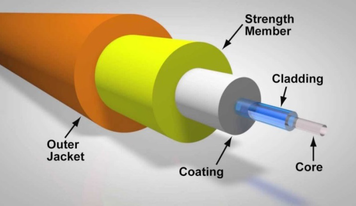
Fig.5. 4: the structure of optical fiber
The light is guided down the core of the fiber by the optical cladding which has
a lower refractive index. Remember that the refractive index is the ratio of the
velocity of light in a vacuum to its velocity in a specified medium. Then light is
trapped in the core through total internal reflection. The other outer parts that
are the strength member and the outer jacket, serve as protectors.
Connecting two optical fibers is done by fusion splicing or mechanical splicing.
It requires special skills and interconnection technology due to the microscopic
precision required to align the fiber cores.
5.1.2 Refractive index of light
When light falls at the interface (boundary) of two media, it is partially reflected
and partially refracted. As it passes from one medium to another it changes itsdirection.
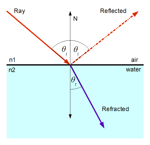
Fig.5. 5: Refraction of light from air to water and water to air for comparison.
The change in its direction is associated with the change in velocity. The ratio of
the speed of light in the vacuum c (or air) and that of light in a certain mediumv is called the absolute refractive index n.
5.1.3 Total internal reflection
When light passes from one a medium of higher index of refraction into a medium
of lower refractive index the light bends away from the normal as indicated on
Fig.6.6. A weak internally reflected ray is also formed and its intensity increasesas the incident angle increases.
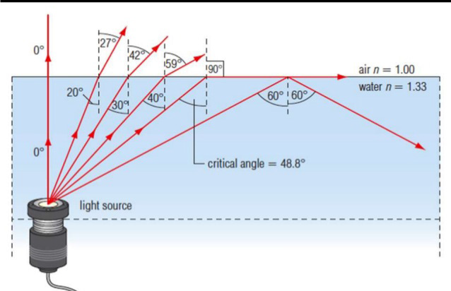
Fig.5. 6: Illustration of total internal reflection
Increasing the angle of incidence increases the angle of refraction and at a
particular incidence, the angle of refraction reaches the 90°. This particular
incident angle is called the critical angle θc. As the incident angle exceeds the
critical angle, the incident beam reflects on the interface between the 2 media
and return in the first medium. This effect is called total internal reflection.For any two media, using Snell’s law the critical angle is calculated using the
expression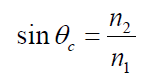
where n1 and n2 are respectively the refractive indices of the first and second
media.θc increases when approaches n1 .
EXAMPLE 5.1
Applying the above relation to the critical ray at a glass-air boundary we
have where index of glass is ng =1.50.
Answer
A beam of light is propagating through diamond, n = 2.42 and strikes a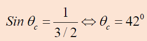
diamond-air interface at an angle of incidence of 28°.
Will part of the beam enter the air or will the beam be totally refracted
at the interface?
Repeat part (a) assuming that diamond is surrounded by water, n = 1.33
Answer:
Since 28° is greater thanθC , total internal reflection will occur, there is norefraction.
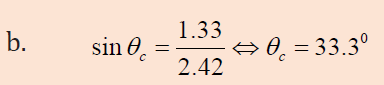
Since 28° is less than θC some light will undergo refraction into the water.
Application:
An optical fiber is basically made of 2 types of glass put together in a concentric
arrangement so the middle is hollow. The inner circle of glass also called the
Core consists of a glass of higher refractive index than the outside layer asindicated on fig.5.4.
Fig.5. 7: Total internal reflection in optical fiber as the angle of incidence θ is greater than the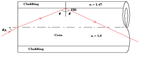
critical angle.
The outer layer of glass, which is also known as the optical cladding, does not
carry light but is essential to maintain the critical angle of the inner glass. The
underlying main physics concept behind the functioning of an optical fiber is a
phenomenon known as total internal reflection.
Any light entering the fiber will meet the cladding at an angle greater than
the critical angle. If light meets the inner surface of the cladding or the core -
cladding interface at greater than or equal to critical angle then total internal
reflection (TIR) occurs. So all the energy in the ray of light is reflected back into
the core and none escapes into the cladding. The ray then crosses to the other
side of the core and, because the fiber is more or less straight, the ray will meet
the cladding on the other side at an angle which again causes the total internal
reflection. The ray is then reflected back across the core again and again until it
reaches the end of the optical fiber.
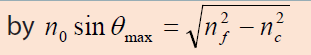
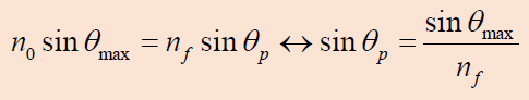
Maximum angle of incidence
The maximum angle of incidence in air for which all the light is total reflected
at the core-cladding is given by: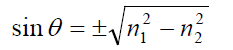
EXAMPLE 6.2
1. An optical fibre consists of an inner material (the fiber) with refractive
index nf and an outer material of lower refractive index nc, known ascladding, as in Fig. 6.6 below.
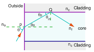
Fig.5. 6
a. What is the purpose of cladding?b. Show that the maximum acceptance angle θmax is given
c. Discuss two main fiber loss mechanisms.
Answer
The purpose of the cladding is to improve the transmission efficiency
of the optical fibre. If cladding is not used then the signal is attenuated
dramatically.
Let a ray be incident at an angle θ , Fig.6.6, the angle of refraction at P
being θp Let C be the critical angle at Q, interface of core and cladding
(in this case θC =θmax )
Refraction from air to core:
This shows that there is a maximum angle of acceptance cone outside of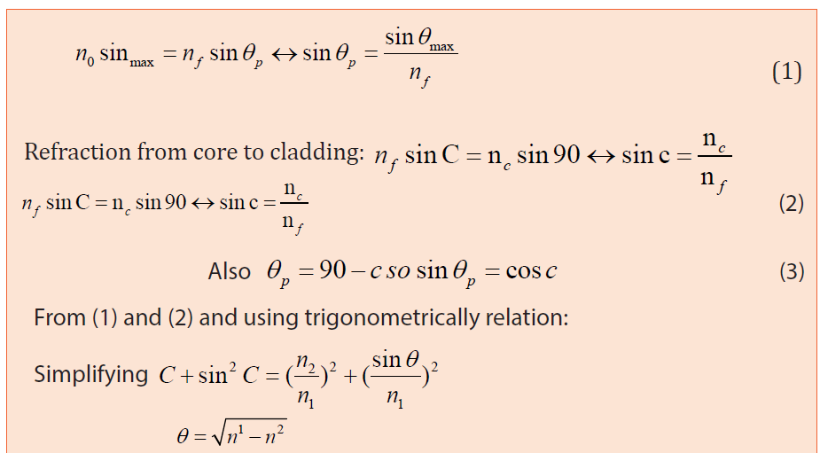
which entering rays will not be totally reflected within the fiber. For the
largest acceptance cone, it is desirable to choose the index of refraction of the
cladding to be as small as possible. This is achieved if there is no cladding at
all. However, this leads to other problems associated with the loss of intensity.
d. The transmission is reduced due to multiple reflections and the absorption
of the fibre core material due to impurities.
2. A step-index fiber 0.01 cm in diameter has a core index of 1.53 and a
cladding index of 1.39. See Fig.5.7. Such clad fibers are used frequently inapplications involving communication, sensing, and imaging.
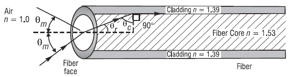
Fig.5. 7
What is the maximum acceptance angle θmfor a cone of light rays incident on
the fiber face such that the refracted ray in the core of the fiber is incident onthe cladding at the critical angle?
5.1.4 Checking my progress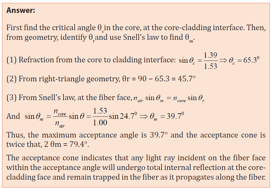
1. Operation of optical fiber is based on:
a. Total internal reflection
b. Total internal refraction
c. Snell’s law
d. Einstein’s theory of reality
e. None of the above
2. When a beam of light passes through an optical fiber
a. Rays are continually reflected at the outside(cladding) of the fiber
b. Some of the rays are refracted from the core to the cladding
c. The bright beam coming out of the fiber is due to the high refractive
index of the core
d. The bright beam coming out of the fiber is due to the total internal
reflection at the core-cladding interface
e. All the rays of light entering the fiber are totally reflected even at very
f. small angles of incidence
3. A laser is used for sending a signal along a mono mode fiber because
a. The light produced is faster than from any other source of light
b. The laser has a very narrow band of wavelengths
c. The core has a low refractive index to laser light
d. The signal is clearer if the cladding has a high refractive index
e. The electrical signal can be transferred quickly using a laser
4. Given that the refractive indices of air and water are 1 and 1,33,
respectively, find the critical angle.
5. The frequency of a ray of light is 6.0x10¹⁴ Hz and the speed of light in air is
3x10⁸ m/s. the refractive index of the glass is 1.5.
a. Explain the meaning of refracting index
b. A ray of light has an angle of incidence of 30° on a block of quartz and an
angle of refraction of 20°. What is the index of refraction of the quartz?
6. A beam of light passes from water into polyethylene (n = 1.5). If θi = 57.5°,
what is the angle of refraction?
7.
a. What is the critical angle when light is going from a diamond (n= 2.42)
to air?
b. Using the answer to (a), what happens when:
I. The angle of incidence is less than that angle?II. The angle of incidence is more than that angle
5.2 TYPES OF OPTICAL FIBERS
ACTIVITY 5.2: Investigating the types of optical fiber.
Use search internet and discuss different types of optical fiber. Then,
differentiate them according to their respective uses.
There are three main types of Optical Fibers: Monomode (or single
mode), Multimode and special purpose optical fibers.
5.2.1 Monomode fibers
Those are Fibers that support a single mode and are called single-mode
fibers (SMF). Single-mode fibers are used for most communication links longerthan 1 000 m.
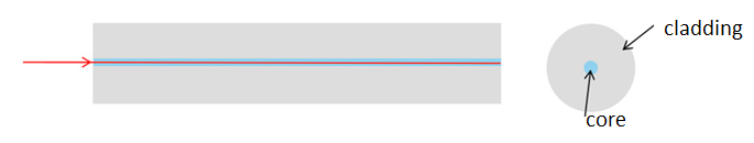
Fig.5. 8: Structure of monomode or single-mode optical fiber
In the monomode fiber, the core is only about 8 μm in diameter, and only
the straight through transmission path is possible, i.e. one mode. This type,
although difficulty and expensive to make, is being used increasingly. For short
distances and low bit-rates, multimode fibers are quite satisfactory. Following
the emergence of single-mode fibers as a viable communication medium in
1983, they quickly became the dominant and the most widely used
fiber type within Telecommunications. Major reasons for this situation are
as follows:
1. They exhibit the greatest transmission bandwidths and the lowest losses of
the fiber transmission media.
2. They have a superior transmission quality over other fiber types
because of the absence of modal noise.
3. They offer a substantial upgrade capability (i.e. future proofing) for future
wide- bandwidth services using either faster optical transmitters or
receivers or advanced transmission techniques (e.g. coherent technology,).
4. They are compatible with the developing integrated optics technology.
5. The above reasons 1 to 4 provide confidence that the installation of singlemode
fiber will provide a transmission medium which will have adequate
performance such that it will not require replacement over its anticipated
lifetime of more than 20 years. (John, 2009)
5.2.2 Multimode fiers
In multimode fier, light travels through the fier following diffrent light paths
called “modes” as indicated on Fig.5.9. Those are fiers that support many
propagation paths. A multi-mode optical fier has a larger core of about 50 μm,
allowing less precise, cheaper transmitters and receivers to connect to it aswell as cheaper connectors
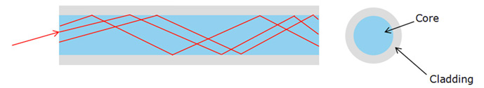
Fig.5. 9 Multimode optical fiber
The propagation of light through a multimode optical fiber is shown on Fg.
5.9. However, a multi-mode fiber introduces multimode distortion, which
often limits the bandwidth and length of the link. Furthermore, because of its
higher dopant content, multi-mode fibers are usually expensive and exhibit
higher attenuation.
There are two types of multi-mode optical fibers: multimode step-index andmultimode graded index (see Fig.5.10)
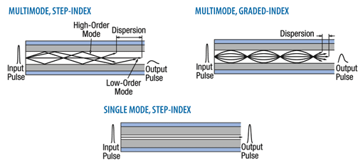
Fig.5. 10: Step index and graded index multimode optical fibers illustration.
• In step-index multimode type, the core has the relatively large
diameter of 50μm and the refractive index changes suddenly at the
cladding. The wide core allows the infrared to travel by several paths
or modes. Paths that cross the core more often are longer, and signals
in those modes take longer to travel along the fiber. Arrival times at the
receiver are therefore different for radiation of the same pulse, 30ns
km-1, being a typical difference. The pulse is said to suffer dispersion,
it means that it is spread out.
• In the graded index multimode type, the refractive index of the glass
varies continuously from a higher value at the center of the fiber to a
low value at the outside, so making the boundary between core and
the cladding indistinct. Radiation following a longer path, travel faster
on average, since the speed of light is inversely proportional to the
refractive index. The arrival times for different modes are the about
the same (to within 1ns km-1) and all arrive more or less together at the
receiving end. Dispersion is thereby much reduced.
5.2.3 Special-purpose optical fiber
Some special-purpose optical fiber is constructed with a non-cylindrical
core and/or cladding layer, usually with an elliptical or rectangular crosssection.
These include: polarization-maintaining fiber and fiber designed to
suppress whispering gallery mode propagation.
• Polarization-maintaining fiber is a unique type of fiber that is
commonly used in fiber optic sensors due to its ability to maintain the
polarization of the light inserted into it.
• Photonic-crystal fiber is made with a regular pattern of index
variation. It is often in the form of cylindrical holes that run along the
length of the fiber. Such fiber uses diffraction effects in addition to total
internal reflection, to confine light to the fiber’s core.
5.2.4 Checking my progress
1. Fiber optics is best known for its application in long-distance
telecommunications.
a. True
b. False
2. Choose the basic types of optical fiber:
a. Single-mode e. Multi-mode
b. X-mode f. A and C
c. Microwave-mode g. B and D
d. Graded-index mode h. A and E
3. Single-mode fiber has the advantage of greater bandwidth capability. It
has the disadvantage of:
a. Being harder to bend
b. Smaller mechanical tolerances in connectors and splices
c. Being difficult to couple light into
d. B and C
e. None of the above
4. Describe with the aid of simple ray diagrams:
a. The multimode step index fiber;
b. The single-mode step index fiber.
c. Compare the advantages and disadvantages of these two types of fiberfor use as an optical channel.
5.3 Mechanism of attenuation
ACTIVITY 5.3: Light transmission analysis in optical fiber
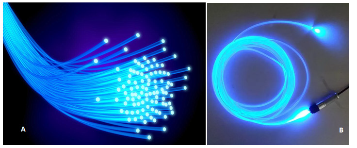
Fig.5. 11 The images to show the attenuation in optical fiber
Observe the image clearly, and answer to the following questions:
1. Does all the light from the source getting to the destination?
2. What do you think is causing the loss in light transmission?
3. What can be done to minimize that loss in the optical fibers above?
Attenuation in fiber optics, also known as transmission loss, is the reduction
in intensity of the light beam (or signal) as it travels through the transmission
medium. Over a set distance, fiber optic with a lower attenuation will allow
more power to reach its receiver than a fiber with higher attenuation.
Attenuation can be caused by several factors both extrinsic and intrinsic:
• Intrinsic attenuation is due to something inherent to the fiber such as
impurities in the glass during manufacturing. The interaction of such
impurities with light results in the scattering of light or its absorption.
• Extrinsic attenuation can be caused by macro bending and
microlending. A bent imposed on an optical fiber produce a strain in
that region of the fiber and affects its refractive index and the critical
angle of the light ray in that area. Macrobending that is a large-scale
bent and microbending which is a small-scale bent and very localized
are external causes that result in the reduction of optical power.
Attenuation coefficients in fiber optics usually are expressed decibels per
kilometer (dB/km) through the medium due to the relatively high quality of
transparency of modern optical transmission media. It is observed that the
attenuation is a function of the wavelength of the light. The attenuation αtot (λ )
at wavelength λ of a fiber between two cross-sections, 1 and 2, separated bydistance Lis defined, as
where
P1 λ optical power at the cross-section 1, and
at the cross-section 2. Attenuation is an important limiting factor in the
transmission of a digital signal across large distances. Thus, much research has
gone into both limiting the attenuation and maximizing the amplification of the
optical signal.
5.3.1 Light scattering and absorption
In the light transmission of signals through optical fibers, attenuation occurs
due to light scattering and absorption of specific wavelengths, in a manner
similar to that responsible for the appearance of color.
a. Light scatteringScattering losses
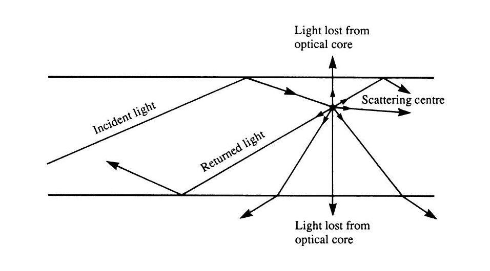
Fig.5. 12: Light scattering in optical fiber
The propagation of light through the core of an optical fiber is based on total
internal reflection of the light wave. Rough and irregular surfaces, even at the
molecular level, can cause light rays to be reflected in random directions as it
is illustrated on Fig.5.12. This is called diffuse reflection or scattering, and it is
typically characterized by wide variety of reflection angles.
Light scattering depends on the wavelength of the light being scattered.
Thus, limits to spatial scales of visibility arise, depending on the frequency
of the incident light-wave and the physical dimension (or spatial scale) of the
scattering center, which is typically in the form of some specific micro-structural
feature. Since visible light has a wavelength of the order of one micrometer (one
millionth of a meter) scattering centers will have dimensions on a similar
spatial scale. Thus, attenuation results from the incoherent scattering of light
at internal surfaces and interfaces.
b. Light absorption
Material absorption is a loss mechanism related to the material composition
and fiber fabrication process. This results in the dissipation of some transmitted
optical power as heat in the waveguide. Absorption is classified into two basic
categories: Intrinsic and extrinsic absorptions. (John, 2009)
Intrinsic absorption: is caused by basic fiber material properties. If an optical
fiber is absolutely pure, with no imperfections or impurities, ten all absorption
will be intrinsic. Intrinsic absorption in the ultraviolet region is caused bands.
Intrinsic absorption occurs when a light particle (photon) interacts with an
electron and excites it to a higher energy level.
5.3.2 Measures to avoid Attenuation
The transmission distance of a fiber-optic communication system has
traditionally been limited by fiber attenuation and by fiber distortion.
• Repeaters: Repeaters convert the signal into an electrical signal, and
then use a transmitter to send the signal again at a higher intensity
than was received, thus counteracting the loss incurred in the previous
segment. They mostly used to be installed about once every 20 km.
• Regenerators: Optical fibers link, in common with any line
communication system, have a requirement for both jointing and
termination of the transmission medium. When a communications
link must span at a larger distance than existing fiber-optic technology
is capable of, the signal must be regenerated at intermediate points
in the link by optical communications repeaters called regenerators.
An optical regenerator consists of optical fibers with special coating
(doping). The doped portion is pumped with a laser. When the
degraded signal comes into the doped coating, the energy from the
laser allows the doped molecules to become lasers themselves. The
doped molecules then emit a new strong light signal with the same
characteristics as the incoming weak signal. Basically, the regenerator
is a laser amplifier for the incoming signal.
• Optical Amplifiers: Another approach is to use an optical
amplifier which amplifies the optical signal directly without having to
convert the signal into the electrical domain. It is made by doping a
length of fiber with the rare-earth mineral erbium and pumping it with
light from a laser with a shorter wavelength than the communications
signal (typically 980 nm). Amplifiers have largely replaced repeaters in
new installations.
5.3.3 Checking my progress
1. True or False: One of the reasons fiber optics hasn’t been used in more
areas has been the improvement in copper cable such as twisted pair.
2. True or False: With current long-distance fiber optic systems using
wavelength-division multiplexing, the use of fiber amplifiers has
become almost mandatory.
3. Fiber optics has extraordinary opportunities for future applications
because of its immense bandwidth.
a. True
b. False
4. a. What do we mean by attenuation in optical fibers?
c. State two ways in which energy is lost in optical fibers.
d. If a fiber loses 5% of its signal strength per kilometer, how much ofits strength would be left after 20 km?
5.4 OPTICAL TRANSMITTER AND OPTICAL RECEIVER
ACTIVITY 5.4: Investigating the signal sources and signal receiver
for optic fibers
1. With the basic information you know about the functioning process
of optical fiber, answer to the following questions.
2. Where does the light that is transmitted into the optical fiber core
medium come from?
3. What are the type compositions of the light signal propagating into
optical fiber?
4. Discuss and explain the function principle of signal generators and
signal receivers of light from optical fibers.
The process of communicating using fier-optics involves the following basic
steps:
1. Creating the optical signal involving the use of a transmitter, usually from
an electrical signal.
2. Relaying the signal along the fier, ensuring that the signal does not
become too distorted or weak.
3. Receiving the optical signal.4. Converting it into an electrical signal
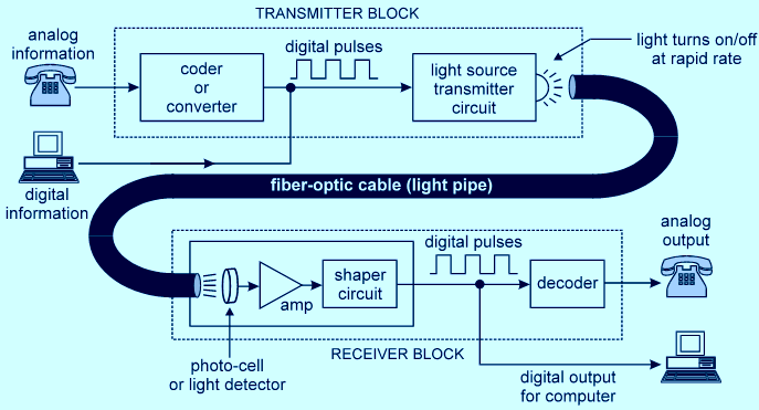
Fig.5. 13: Optical fiber communication mechanism (Transmitter and receiver blocks).
5.4.1 Transmitters
The most commonly used optical transmitters are semiconductor devices
such as light-emitting diodes (LEDs) and laser diodes. The difference between
LEDs and laser diodes is that LEDs produce incoherent light, while laser diodes
produce coherent light. For use in optical communications, semiconductor
optical transmitters must be designed to be compact, efficient and reliable,
while operating in an optimal wavelength range and directly modulated at high
frequencies (see Fig.5.13: Transmitter block).
In its simplest form, a LED is a forward-biased p-n junction, emitting
light through spontaneous emission, a phenomenon referred to
as electroluminescence. The emitted light is incoherent with a relatively wide
spectral width of 30–60 nm. LED light transmission is also inefficient, with
only about 1% of input power, or about 100 microwatts, eventually converted
into launched power which has been coupled into the optical fiber. However, due
to their relatively simple design, LEDs are very useful for low cost applications.
5.4.2 The Optical Receivers
The main component of an optical receiver is a photodetector (photodiode)
which converts the infrared light signals into the corresponding electrical
signals by using photoelectric effect before they are processed by the decoder
for conversion back into information. The primary photo detectors fortelecommunications are made from Indium gallium arsenide (see Fig.5.13).
The photodetector is typically a semiconductor-based photodiode. Several
types of photodiodes include p-n photodiodes, p-i-n photodiodes, and avalanche
photodiodes. Metal-semiconductor-metal (MSM) photodetectors are also used
due to their suitability for circuit integration in regenerators and wavelengthdivision
multiplexers.
5.4.3 Checking my progress
1. Circle the three basic components in a fiber optic communications system.
a. Telescope e. Maser fiber
b. Transmitter f. Optical fiber
c. Receiver G. Alternator
d. Surveillance satellites
2. Information (data) is transmitted over optical fiber by means of:
a. Light d. Acoustic waves
b. Radio waves e. None of the above
c. Cosmic rays
3. Connectors and splices add light loss to a system or link.
a. True
b. False
4. Do fibers have losses?
5.5. USES OF OPTICAL FIBERS
ACTIVITY 6.5: Applications of fiber optics in telecommunication
and in medicine
Use the internet or the library to investigate the applications of optical
fiber in medicine and telecommunication systems.
5.5.1. Telecommunications Industry
Optical fibers offer huge communication capacity. A single fiber can carry the
conversations of every man, woman and child on the face of this planet, at the
same time, twice over. The latest generations of optical transmission systems
are beginning to exploit a significant part of this huge capacity, to satisfy the
rapidly growing demand for data communications and the Internet.
The main advantages of using optical fibers in the communications industry
are:
1. A much greater amount of information can be carried on an optical fiber
compared to a copper cable.
2. In all cables some of the energy is lost as the signal goes along the cable.
The signal then needs to be boosted using regenerators. For copper cable
systems these are required every 2 to 3km but with optical fiber systems
they are only needed every 50km.
3. Unlike copper cables, optical fibers do not experience any electrical
interference. Neither will they cause sparks so they can be used in explosive
environments such as oil refineries or gas pumping stations.
4. For equal capacity, optical fibers are cheaper and thinner than copper
cables and that makes them easier to install and maintain.
5.5.2 Medicine Industry
The advent of practicable optical fibers has seen the development of much
medical technology. Optical fibers have paved the way for a whole new field of
surgery, called laproscopic surgery (or more commonly, keyhole surgery), which
is usually used for operations in the stomach area such as appendectomies.
Keyhole surgery usually makes use of two or three bundles of optical fibers.
A “bundle” can contain thousands of individual fibers”. The surgeon makes a
number of small incisions in the target area and the area can then be filled with
air to provide more room.
One bundle of optical fibers can be used to illuminate the chosen area, and
another bundle can be used to bring information back to the surgeon. Moreover,
this can be coupled with laser surgery, by using an optical fiber to carry the
laser beam to the relevant spot, which would then be able to be used to cut the
tissue or affect it in some other way.
5.5.3 Checking my progress
The basic unit of digital modulation is:
a. Zero c. A and Bb. One d. None of the above
5.6 ADVANTAGES AND DISADVANTAGES OF OPTICAL FIBERS
ACTIVITY 5.6: Advantages and disadvantages of optical fibers
Use search internet or your library to investigate the advantages and
disadvantages of fiber optics.
Although there are many benefits to using optical fibers, there are also
some disadvantages. Both are discussed below:fiber in medicine and
telecommunication systems.
5.6.1 Advantages
• Capacity: Optical fibers carry signals with much less energy loss than
copper cable and with a much higher bandwidth. This means that
fibers can carry more channels of information over longer distances
and with fewer repeaters required.
• Size and weight: Optical fiber cables are much lighter and thinner than
copper cables with the same bandwidth. This means that much less
space is required in underground cabling ducts. Also they are easier for
installation engineers to handle.
• Security: Optical fibers are much more difficult to tap information from
undetected; a great advantage for banks and security installations.
They are immune to electromagnetic interference from radio signals,
car ignition systems, lightning etc. They can be routed safely through
explosive or flammable atmospheres, for example, in the petrochemical
industries or munitions sites, without any risk of ignition.
• Running costs: The main consideration in choosing fiber when
installing domestic cable TV networks is the electric bill. Although
copper coaxial cable can handle the bandwidth requirement over the
short distances of a housing scheme, a copper system consumes far
more electrical power than fiber, simply to carry the signals.
5.6.2 Disadvantages
• Price: In spite of the fact that the raw material for making optical fibers,
sand, is abundant and cheap, optical fibers are still more expensive per
metre than copper. Having said this, one fiber can carry many more
signals than a single copper cable and the large transmission distances
mean that fewer expensive repeaters are required.
• Special skills: Optical fibers cannot be joined together (spliced) as an
easily as copper cable and requires additional training of personnel
and expensive precision splicing and measurement equipment.
5.6.3 Checking my progress
1. List two advantages of using optical fiber. __________________________
2. The replacement of copper wiring harnesses with fiber optic cabling
will increase the weight of an aircraft.
a. Trueb. False
END UNIT ASSESSMENT 5
1. a. An endoscope uses coherent and non−coherent fiber bundle
I. State the use of the coherent bundle and describe its arrangement
of fibers.
II. State the use of the non−coherent bundle and describe its
arrangement of fibers.
b. Each fiber has a core surrounded by cladding. Calculate the critical
angle at the core−cladding interface.
Refractive index of core = 1.52
Refractive index of cladding = 1.
2. (a)Fig.5.9 shows a ray of light travelling through an individual fiber
consisting of cladding and a core. One part has a refractive index of1.485 and the other has a refractive index of 1.511.
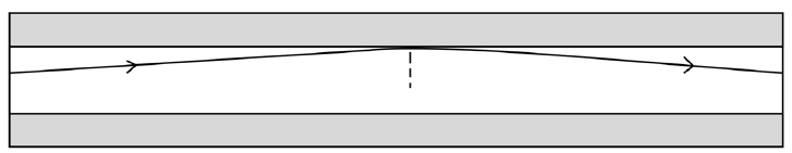
Fig.5. 9: Light transmission in optical fiber.
I. State which part of the fiber has the higher refractive index and
explain why.
II. (ii) Calculate the critical angle for this fiber.
(b) The figure below shows the cross-section through a clad opticalfiber which has a core of refractive index 1.50.
Complete the graph below to show how the refractive index changes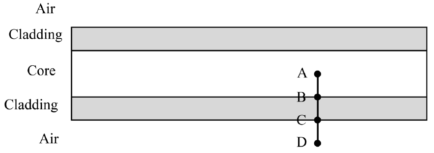
with the radial distance along the line ABCD in the figure above.
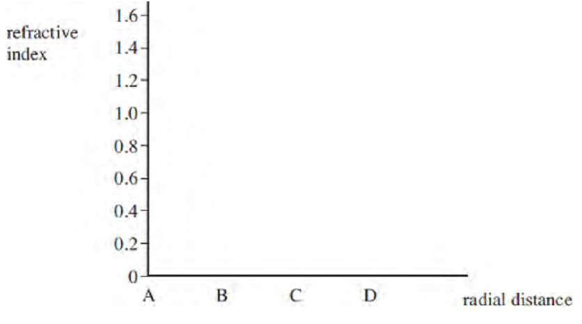
Fig.5. 11: Axes for the half life decay curve
3.
a. What do we mean by attenuation in optical fibers?
b. State two ways in which energy is lost along the length of an
optical fiber.
c. If a fiber loses 5% signal strength per km, how much strength
would be left after 20 km?
4. Estimate the length of time it would take a fiber optic system to
carry a signal from the UK to the USA under the Atlantic. (Take c =
2 x 10⁸ m/s in the cable. Estimate the length of the cable under the
sea.
a. Estimate the length of time it would take a microwave signal to
travel from the UK to the USA a satellite Enk. (Geosynchronous
satellites orbit at a height of about 36 000 Ian above the Earth’s
surface.b. Which would give less delay in a telephone conversation?