Unit 5 : Kirchhoff ’s Laws and Electric Circuits
Key Unit Competence
Analyse the complex electric circuits using Kirchhoff’s laws
My goals
By the end of this unit, I will be able to:
* analyse complex electric circuits using Kirchhoff’s laws.
* identify sources of electric current.
* describe components of simple electric circuits.
* state Kirchhoff’s laws and apply them to solve problems in electric
circuits.
* acquire practical skills to manipulate apparatus and evaluate
experimental producers.
* explain the differences between the potential difference and
electromotive forces.
Introductory activity
Provided two bulbs, cell holder, bulb holder, voltmeter, ammeter, connecting
wires and a switch.
1. Make a simple electric circuit (as in the above figure) and comment
on your observation
2. On the circuit made in (1), add a voltmeter and an ammeter.
3. What would happen if you remove one bulb from the circuit?
4. Would there be another type of connection of the circuit? Try it and
comment your observation.
5. Discuss on the function of each element in provided list.
Introduction
This unit is one of the most interesting units in Physics. Even if you
ask someone who did not have enough studies in Physics he or she
will tell you that People studying physics will be engineers specifically
electricians. This Unit addresses the principles those electricians use in
their career.
Review of elements of simple electric circuits
and their respective role
An electric current consists of moving electric charges. Electric current must
flow in electric devices connected by conductors (wires). The motion of
electrons in a conductor is compared to water flow in a pipe. To move electrons,
there must be a source of electric current, a cell, a battery, a generator which
acts as a pump of water.
Making a simple circuit
Activity 1
Making a simple electric circuit with a bulb, a battery and wires
Materials:
* 2 pieces of copper wire
* 1 bulb
* 1 battery
Procedure
1. Examine diagrams A-J below. Predict whether the circuit will be
complete, and record your prediction on the chart below.
2. Demonstrate the arrangements to test your predictions..
PREDICTION CHART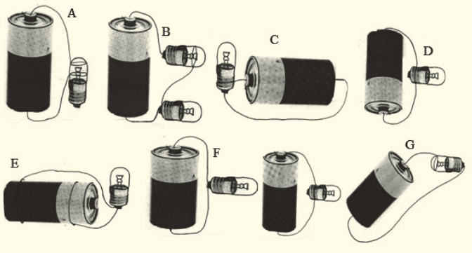
Activity 1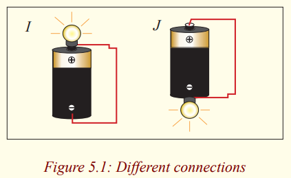
What makes the bulb light?
You may already understand an electrical circuit, or this may seem
like magic to you. Give what your teacher demonstrated some thought.
Why do you think the bulb in the diagram lights?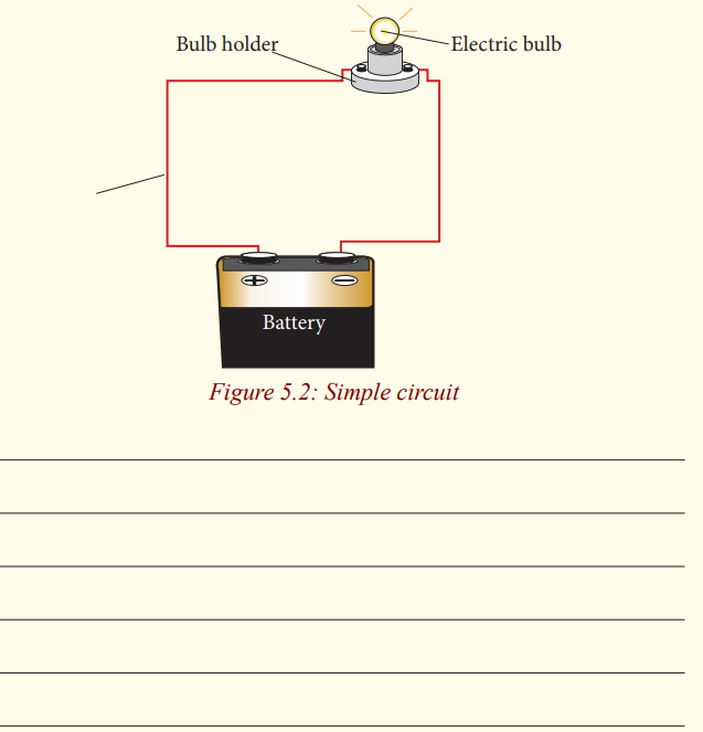
It would be useful here to summarize some basic electricity points which
you may know already.
a) A current flows along a metal or wire when a battery is
connected to it.
b) The current is due to free electrons moving along the metal.
c) The battery has a potential difference p.d or voltage
between its poles due to chemical changes inside thebattery. The p.d. pushes the electrons along the metal.
One pole of the battery is called the positive (+) pole, the other is called the
negative (-) pole. The “conventional” current, shown by an arrow, flows
in a circuit connected from the + to the – pole. The electrons carrying the
current along the circuit wires actually move in the opposite direction to the
conventional current but this need not to be taken in account in calculations
or circuit formulae.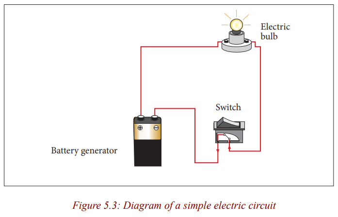
Any path along which electrons can flow is a circuit. For a continuous flow
of electrons, there must be a complete circuit with no gaps. A gap is usually
provided by an electric switch that can be opened or closed to either cut off orallow energy flow.
Most circuits contain more than one device that receives electric energy
from the circuit. These devices are commonly connected in a circuit in one
of two ways, series or parallel. When connected in series, the devices and
wires connecting them form a single pathway for electron flow between the
terminals of the battery, generator or wall socket. When connected in parallel,
the devices and wires connecting them form branches, each of which is aseparate path for the flow of electrons.
Making a series and parallel circuit
Activity 2
Making a series circuit
Materials:
* 1 Battery .
* 3 Bulbs.
* 3 bulb holders .
* Assembled battery holder.* 4 Pieces of copper wire (as needed).
Procedure
1. Construct a complete circuit with a battery and a bulb.
2. Using another wire, add a second bulb as shown on the picturebelow.
3. What did you notice happened to the first bulb when the second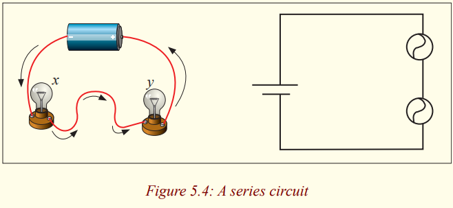
bulb was added?
_____________________________________________________
_____________________________________________________
_____________________________________________________
4. Look carefully at how the series circuit is set up. Write a prediction
of what you think will happen if you unscrew one of the bulbs.
_____________________________________________________
__________________________________________________________________________________________________________
Why did you make this prediction?
_____________________________________________________
__________________________________________________________________________________________________________
5. Unscrew bulb “X”. Describe what happens to bulb “Y”.
_____________________________________________________
__________________________________________________________________________________________________________
6. Tighten bulb “X”, and unscrew bulb “Y”. Describe what happens
to bulb “X”.
_____________________________________________________
__________________________________________________________________________________________________________
7. Add a third bulb to your series circuit. What happens to the brightness
of the bulbs each time another bulb is added to the series?
_____________________________________________________
__________________________________________________________________________________________________________
8. Add a third bulb to your series circuit. What happens to the brightness
of the bulbs each time another bulb is added to the series?
_____________________________________________________
__________________________________________________________________________________________________________
9. Draw a schematic diagram of the circuit you constructed with
three bulbs.
Activity 3
Making a parallel circuit
Materials:
* 1 battery
* 3 bulbs
* Assembled battery holder 3 bulb holders* 6 pieces of copper wire
Procedure
1. Construct a complete circuit with one battery and one bulb.
2. Using another two wires, add a second bulb as shown in the figurebelow.
3. What do you notice happened to the first bulb when the second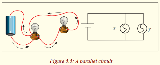
bulb was added?
_____________________________________________________
__________________________________________________________________________________________________________
4. Look carefully at how a parallel circuit is set up. Write a
prediction of what you think will happen if you unscrew one of
the bulbs in the parallel circuit.
_____________________________________________________
__________________________________________________________________________________________________________
Why did you make this prediction?
_____________________________________________________
__________________________________________________________________________________________________________
5. Unscrew bulb “X”. Describe what happens to bulb “Y”.
_____________________________________________________
__________________________________________________________________________________________________________
6. Tighten bulb “X” and unscrew bulb “Y”. Describe what happens
to bulb “X”.
_____________________________________________________
__________________________________________________________________________________________________________
After carrying out experiments for series and parallel circuits,
* What advantages and disadvantages can you note for the two cases?
* What are the characteristics of a series connection and a parallelconnection?
Application activity 5.1
1. If a battery provides a high voltage, it can ____.
a. do a lot of work over the course of its lifetime
b. do a lot of work on each charge it encounters
c. push a lot of charge through a circuit
d. last a long time
2. Which of the following is true about the electrical circuit in your
flashlight?
a) Charge moves around the circuit very fast - nearly as fast as
the speed of light.
b) The battery supplies the charge (electrons) which move
through the wires.
c) The battery supplies the charge (protons) which move through
the wires.
d) The charge becomes used up as it passes through the light
bulb.
e) The battery supplies energy which raises charge from low to
high voltage.f) Nonsense! None of these are true.
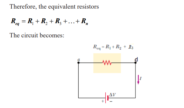
series connections of resistors
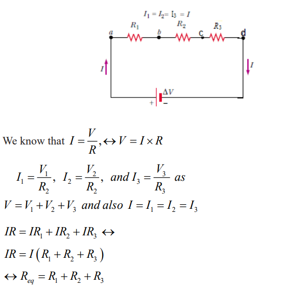
For a series combination of two resistors, the currents are the same in both
resistors because the amount of charge that passes through R1 must also passthrough R2 and R3 in the same interval of time.
The potential difference at the generators is equal to the sum of potential
difference at each resistor mean that The potential difference applied acrossthe series combination of resistors will divide between the resistors.
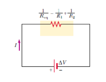
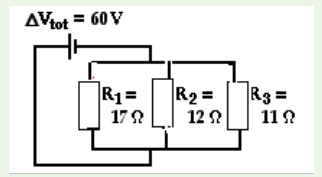
Parallel connection of resistors
The total current equal to the sum of the current pass through the separatebranches.
The potential difference is the same at each resistor and at the generator or
cell.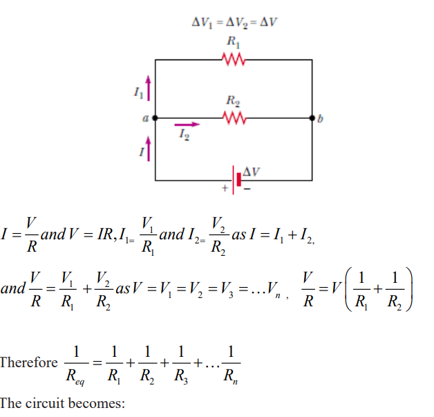
Conclusion
Series and parallel connections each have their own distinctive characteristics.
In a series circuit, the current is the same at all points; it is not used up. In a parallelcircuit the total current equals the sum of the currents in the separate branches.
Application activity 5.2
1. As the number of resistors in a series circuit increases, the overall
resistance ______ (increases, decreases, remains the same)
and the current in the circuit _______ (increases, decreases,
remains the same).+
2. Three resistors are connected in series. If placed in a circuit with
a 12 V power supply. Determine the equivalent resistance, the
total circuit current, and the voltage drop across and current at
each resistor.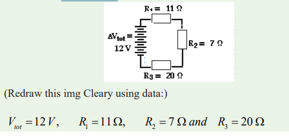
3. Determine the values of the current at and electric potential differenceacross each of the resistors in a parallel circuit.
Generators and receptors
Electromotive force
Activity 4Electromotive force of a generator
Materials
* Battery of 6V,
* Rheostat
* Voltmeter
* Ammeter* Connecting wires
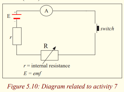
Procedure1. Make the connection as shown in the following figure.
2. Write down the voltage and the current indicated by the voltmeter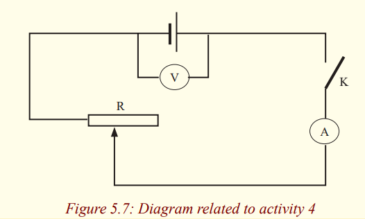
and the ammeter when the switch is open.
3. Close the switch and vary the current in the circuit by varying the
values of the rheostat and every time write down values of voltageand current indicated respectively by voltmeter and Ammeter.
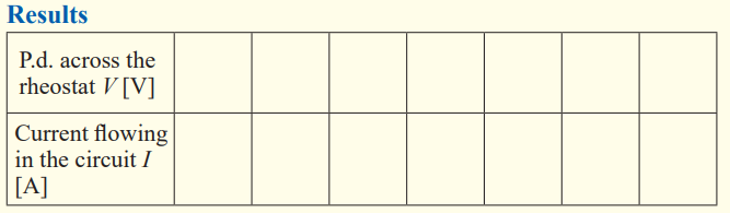
4. Fill in the following table the obtained data:
5. When you vary the value of the resistance of the rheostat, does the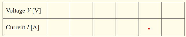
intensity of current remain constant? Why?
6. Does the voltage remain constant?
7. What is the maximum voltage that you have got? How is thisvoltage called?
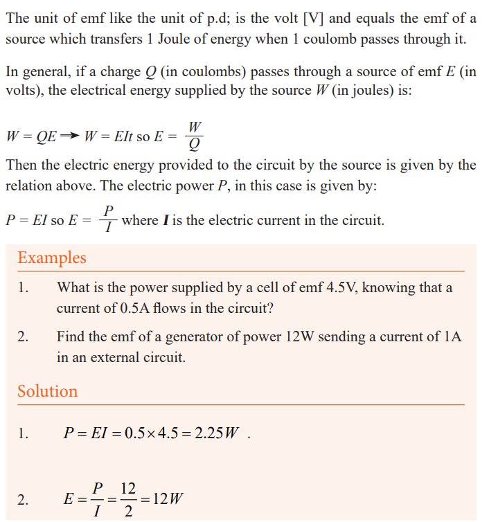
8. In general, if a charge Q (in coulombs) passes through a source of
emf E (in volts) which relation will give the electrical energy Wsupplied by the source (in joules)?
9. Which relation will give the total power of the source?Interpretation
A voltmeter connected to terminals of a battery measures the voltage between
terminals of battery. When the switch was closed, we have noticed that therewas a current across the circuit and the value of the voltage has been changed.
By varying the value of the resistance of the rheostat, current in the circuit is
changed; voltage indicated by the voltmeter changes also, it decreases when
current increases. Its maximum value is reached when the switch is open.Such voltage is called electromotive force E (emf) of the battery.
The electromotive force emf E of a source (a battery, generator, etc) is the
energy transferred to electrical energy when unit charge passes through it.
In other words, we can say that the emf of a source of electrical energy is itsterminal p.d. on open circuit.
The emf of a battery is the maximum possible voltage that the battery canprovide between its terminals.
Internal resistance
Activity 5
Existence of internal resistance in a generator
* Consider a certain number of cells which you put in an electricapparatus, like a radio…
* With your cheek, feel their temperatures before use.
* Put the cells in your apparatus and let them work for a certain time.
* Remove the cells and again with your cheek, feel the newtemperature of the cells then answer the following questions:
• Are the two temperatures of the cells equal? (Before and after
use)
• If not, what do you think is the cause of different temperatures?
• Is one part of the current produced by the generator consumed byit? Why?
* The same observations can be made by feeling the temperature of
the battery of a telephone before a call and after a call of about 10
minutes. Have you felt the increasing of temperature of a phone afterusing it? If yes, you think it’s due to what?
The term internal resistance refers to the resistance within an emf. The terminal
p.d. of a cell on closed circuit is also the p.d. applied to the external circuit.
In an external circuit electrical energy is changed onto other forms of energy
and we regard the terminal p.d. of a cell on closed circuit as being the numberof joules of electrical energy changed by each coulomb in the external circuit.
Not all the electrical energy supplied by a cell to each coulomb is changed
in the external circuit. The “lost” energy per coulomb is due to the cell itself
having resistance. Each coulomb has to “waste” some energy to get through
the cell itself and so less is available for the external circuit. The resistance of
a cell is called its internal resistance [r] and depends among other things onits size.
The electric power dissipated as heat in a cell is given by: Pi = I2 r
Examples
1. The power dissipated as heat in a cell is of 7W, find its internal
resistance if a current of 2A flows through it.
2. Find the power dissipated as heat in a generator of internalresistance 0.6Ω crossed by a current of 3A.
Solution
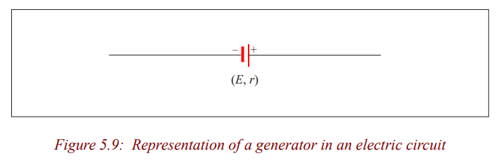
Remark: Any electrical generator, then, has two important properties,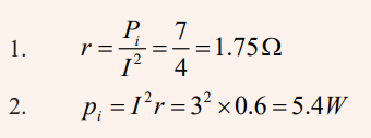
an emf E and an internal resistance r. E and r may be
represented separately in a diagram, though in practice they
are together between the terminals. To represent a cell, we
can write (E, r). So we can think of the battery as an “electric
pump”, with its emf E pushing the current round the circuit
through both the external (outside) resistor R and internalresistance r
In an electric circuit, a generator is then represented by the following symbol:
Activity 6
Experiment to find the emf (E) and the internal resistance (r) of acell
Materials
* 1.5V (approx) cell,
* Resistance box,
* Push switch,* Digital Ammeter (0-1A).
Relationship between the P.d and the emf at terminals of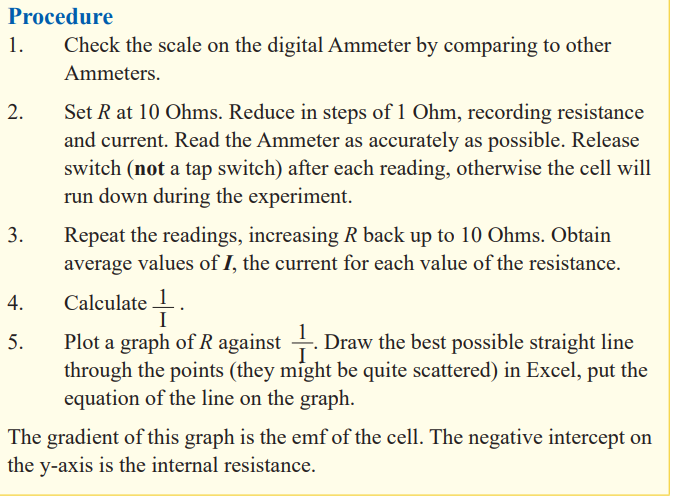
a cell of a closed circuit
Activity 7
Relation between the Emf and the P.d
Materials
* Dry cell,
* Analogy multimetres (2),* Rheostat and switch.
Procedure1. Set up the circuit as shown.
2. Set the resistance of the rheostat to a large value to protect the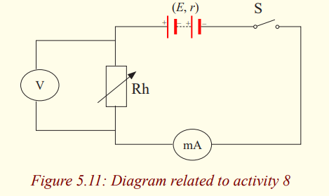
circuit before switch on the circuit.
3. Set the milliammeter to the range 0-1 A or suitable range.
4. Set the voltmeter to the range 0-5V or suitable range.
5. Switch on the circuit. Record down the readings of the Ammeter
and voltmeter. Slide the rider of the rheostat to another position.
Record the readings of the ammeter and voltmeter again. Tabulatethe results.
Examples
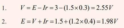
1. What is the voltage at terminals of a battery of emf 3V and internal
resistance 0.3 Ω when sending a current of 1.5 A in a circuit?
2. Knowing that the voltage at terminals of a cell is 1.5V and the
current crossing the circuit is 1.2 A. Find its emf if its internalresistance is of 0.4 Ω.
Solution
Efficiency of a cell
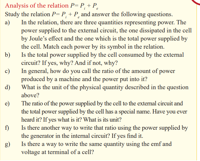
Activity 8
Since the relation above involves the total power in the circuit, which is the
sum of the power supplied in the external circuit and the power dissipated in
the cell itself, this one is useful. It’s used to find the efficiency of the cell andhow to calculate the voltage at terminals of a cell or battery.
To calculate the efficiency of the cell.
Ohm’s law for a circuit having a cell and a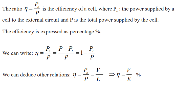
resistor
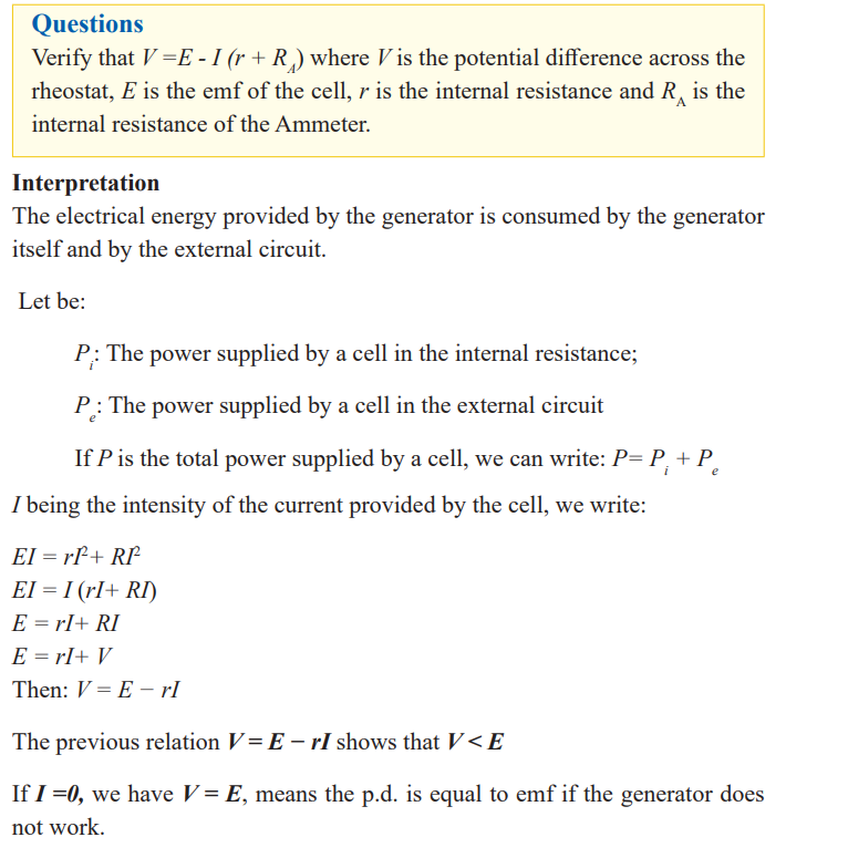
Activity 9
From the observation of the following diagram and analysingdifferent elements deduce a relation
Questions:
a) State the Ohm’s law.b) Observe the following diagram and list constituting elements.
c) Do these elements make an electric circuit? If yes, why?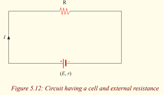
d) Are these elements connected in series or in parallel? Why?
e) How can you find the total resistance of a series connection?
f) Having the total power supplied by a cell, the power supplied by a
cell in an external circuit and the power distributed by the internal
resistance. Write the relation between them.
g) Write down relations for each type of power and substitute them
in the relation above. (Powers dissipated in internal and external
resistances must be written in terms of resistance)
h) From the relation found, deduce the emf E. The relation found
expresses the Ohm’s law for a circuit having a cell and a resistor.i) Express the intensity of the current for this specific case.
Pouillet’s law
We can obtain a form of Ohm’s law by considering a segment of straight
wire of uniform cross-sectional area A and length , as shown in Figure 5.8.
A potential difference is maintained across the wire, creating in the wire anelectric field and a current.
The equation representing the dependency of the resistance (R) of a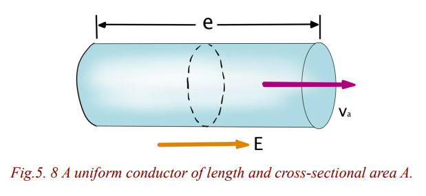
cylindrically shaped conductor (e.g., a wire) upon the variables which affectit, is called Pouillet’s law,
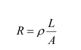
where
• L represents the length of the wire (in m). The longer the wire, the more
resistance that there will be
• A represents the cross-sectional area of the wire (in m2). The wider the wire,
the less resistance that there will be to the flow of electric charge. When all
other variables are the same, charge will flow at higher rates through wider
wires with greater cross-sectional areas than through thinner wires.
•represents the resistivity of the material (in ). Some materials are better
conductors than others and offer less resistance to the flow of charge; they
are better conductors. Silver is one of the best conductors but is never used
in wires of household circuits due to its cost. Copper and aluminum are
among the least expensive materials with suitable conducting ability to
permit their use in wires of household circuits.
Resistivity of a material is numerically the resistance of a sample of unit
length and unit cross-section area, at a certain temperature. The resistivity
of a material is dependent upon the material's electronic structure and its
temperature. For most (but not all) materials, resistivity increases withincreasing temperature.
Application activity 5.3
1. The total power of a battery is of 9V and its internal resistance 3Ω.
Knowing that the current crossed is of 0.4A. Find the efficiency of
the battery.
2. A generator of internal resistance 2Ω sends a current of 4A in a
resistor of resistance 10Ω. Calculate its power.
3. An external resistance of 4Ω is connected to an electric cell of
emf 1.5V and internal resistance 2Ω. Calculate the intensity of the
current flowing the external resistance.
4. An electric cell of emf 1.5V and internal resistance 2Ω is
connected in series with a resistance of 28Ω. Calculate the power
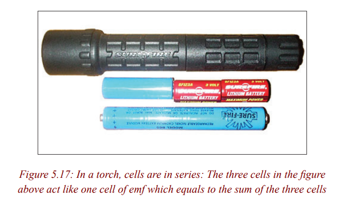
dissipated as heat in the cell.Combination of cells
Activity 10
Cells wired in parallel and in series
Materials:
* 3 batteries
* 2 bulbs
* 3 assembled battery holders
* 2 bulb holders
* 6 pieces of copper wireProcedure
1. Construct a complete circuit with one battery and one bulb.
2. Observe the brightness of the bulb.
3. Construct the circuit below. Are these batteries in series or parallel?
_____________________________________________________
__________________________________________________________________________________________________________
How can you tell?
_____________________________________________________
__________________________________________________________________________________________________________
4. Observe the brightness of this bulb. Is the bulb brighter than it was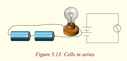
with one battery?
_____________________________________________________
__________________________________________________________________________________________________________
5. If you added a third battery to this circuit in series, what do you
think would happen to the brightness of the bulb?
_____________________________________________________
__________________________________________________________________________________________________________
Why do you think this?
_____________________________________________________
__________________________________________________________________________________________________________
6. Add a third battery to this circuit. Describe what happens to the bulb
as this battery is added to this circuit in series and why you think the
bulb is acting in this way.
_____________________________________________________
__________________________________________________________________________________________________________
7. Construct another complete circuit with one battery and one
bulb. Record again what the brightness of the bulb is using yourbrightness metre.
8. Look at the pictures below, are the batteries in the picture in series
or parallel?
_____________________________________________________
__________________________________________________________________________________________________________
How can you tell?
_____________________________________________________
__________________________________________________________________________________________________________
Construct the circuit in 8. Is the bulb brighter with two batteries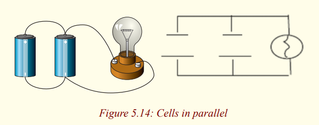
than it was with one battery?
_____________________________________________________
__________________________________________________________________________________________________________
9. Add one more battery to this circuit in parallel. Describe what
happens to the bulb as one more battery is added to this circuit in
parallel and why you think the bulb is acting this way.
_____________________________________________________
__________________________________________________________________________________________________________
10. Connect then two batteries in opposition to mean the positive
(negative) terminals of batteries are connected together and the
two free negative (positive) terminals are connected to the bulb.
What happens to the bulb?
_____________________________________________________
__________________________________________________________________________________________________________
11. Connect two batteries in series in opposition with one battery.
When the two free ends of the combination are connected to
terminals of the bulb, what happens to the brightness of the bulb?
_____________________________________________________
__________________________________________________________________________________________________________
Interpretation
Combination in series
When two or more cells are arranged in series, the total emf is the algebraic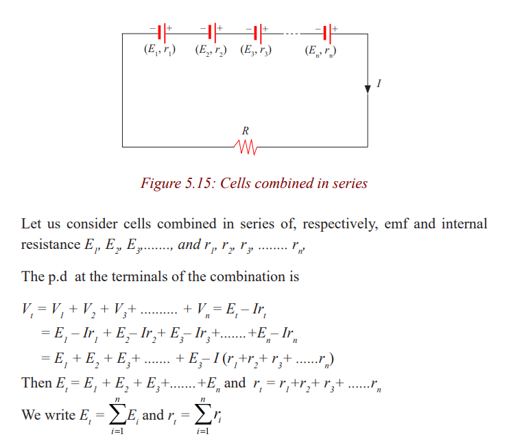
sum of their emfs and the total internal resistance is the algebraic sum of theirinternal resistances
Note: A series arrangement is used to increase the voltage, also the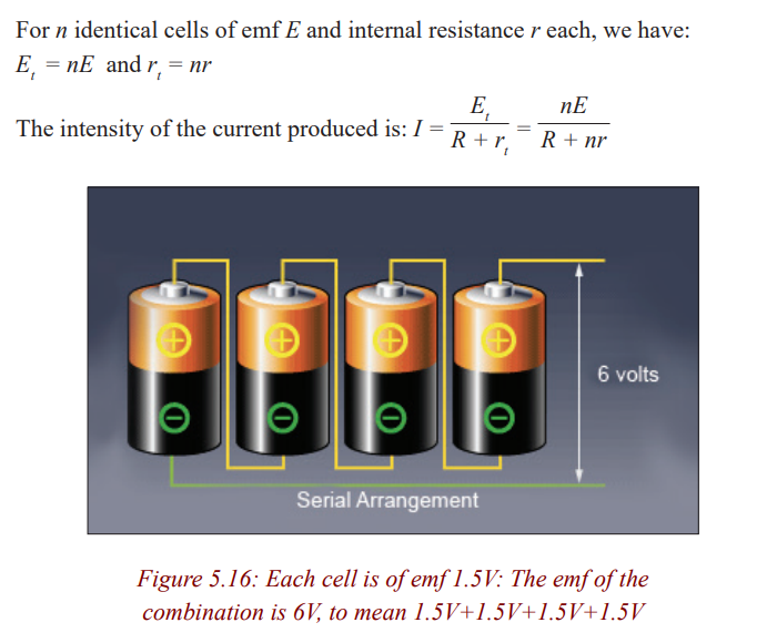
total internal resistance of the circuit, so the energy loss due tointernal resistance is greater than for a single cell.
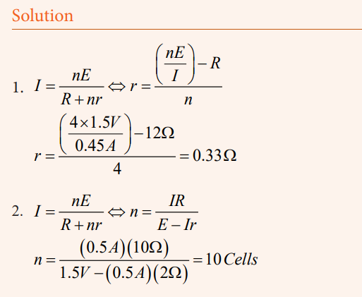
Examples
1. Four 1.5V cells are connected in series to a 12Ω lightbulb. If the
resulting current is 0.45A, what is the internal resistance of eachcell, assuming they are identical and neglecting wires?
2. A certain number of cells of emf 1.5V and internal resistance
2Ω are connected in series. When connected this combination to
an external resistance of 10Ω, a current of 500mA flows in thisresistance. Find the number of cells used.
Combination in opposition
Let us see also what the result could be if the cells were associated in opposition
Let us combine two cells in opposition. Two terminals of same sign are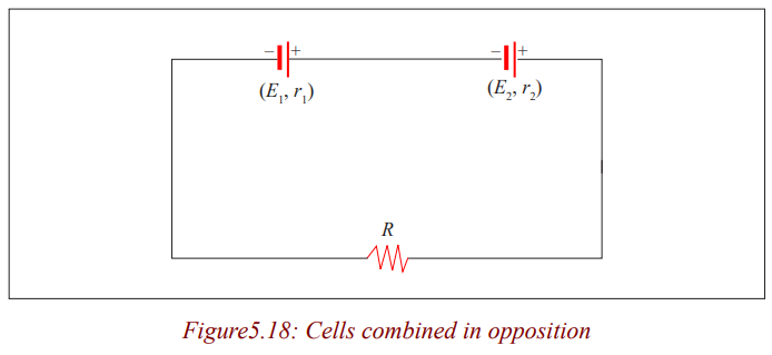
connected together. The direction of the current in the circuit will be determined
by the direction of the current produced by the cell having the higher emf. Forinternal resistances they are in series. So we write:
Note: You might think that connecting batteries in opposition would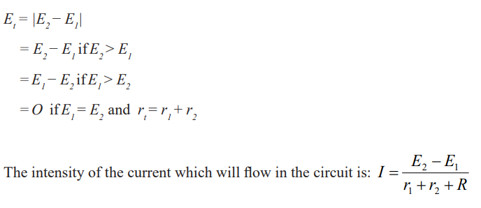
be wasteful. For more purposes, that will be true. But such
an opposition arrangement is precisely how a battery chargerworks.
Example
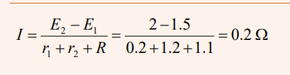
A cell of emf 2V and internal resistance 0.2Ω is associated in opposition
with another cell of emf 1.5V and internal resistance 1.2Ω. Calculate theintensity of the current knowing that the external resistance is 1.1Ω.
Solution
Combination in parallel
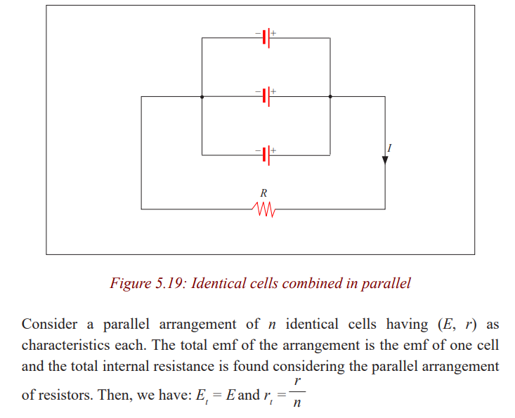
Note: The parallel arrangement is useful normally only if the emfs are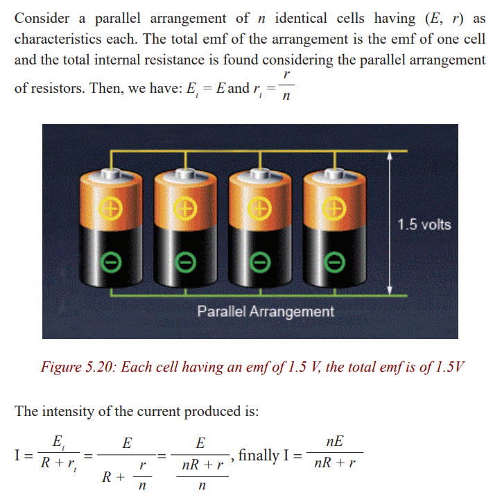
the same. A parallel arrangement is not used to increase the
voltage, but rather to provide large currents. Each of the cells
in parallel has to produce only a fraction of the total current,
so the energy loss due to internal resistance is less than for asingle cell; the batteries will be exhausted less quickly.
Examples
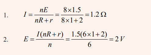
1. We have 8 cells of emf 1.5V and internal resistance 2Ω. Calculate
the intensity of the current flowing in an external resistance of 1Ωconnected to the terminals of the 8 cells combined in parallel.
2. Six cells of unknown emf and internal resistance of 2Ω are
associated in parallel. When an external resistance of 1Ω is
connected to this combination a current of 1.5A is produced.Calculate the emf.
Solution
Mixing series and parallel combinations
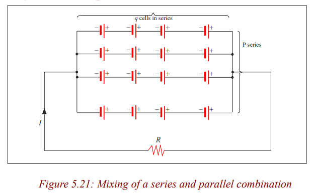
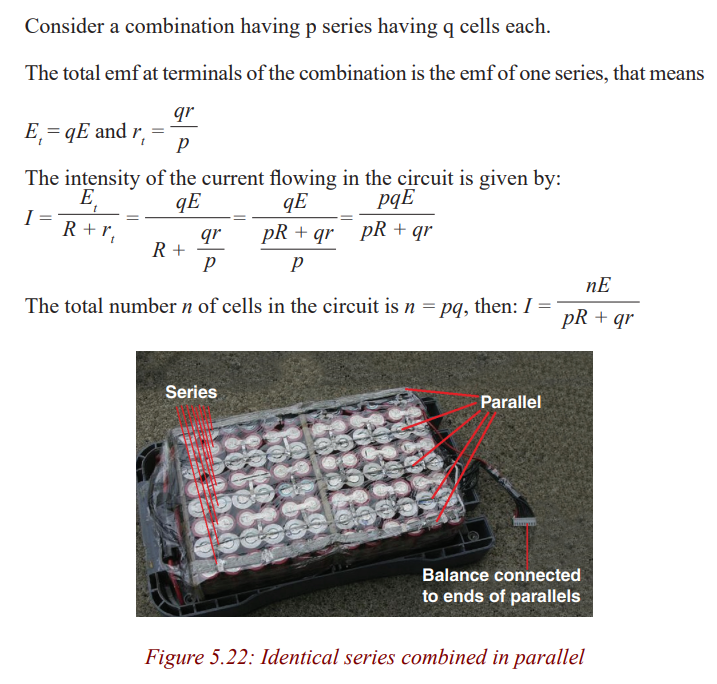
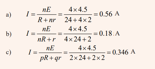
Example
Four cells of emf 4.5V each and internal resistance 2Ω are combined in
series. The combination is connected to an external resistance of 24Ω
a) What is the intensity of the current?
b) Same question if the cells are combined in parallel.
c) Same question if the combination has two parallel series of twocells each.
Solution
Receptors
Activity 11
Distinguishing a receptor from a passive resistor
a) Observe the following devices and name them
b) What is the use of each one?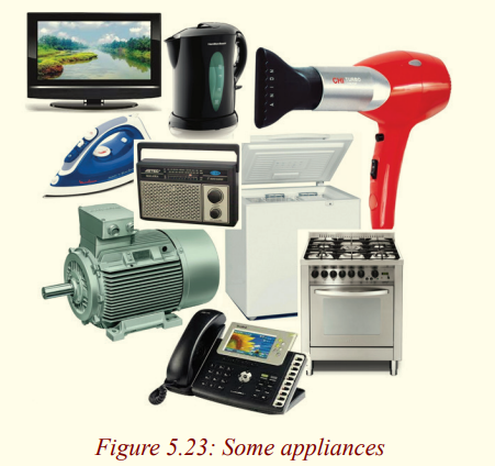
c) The flowing of the current in them produces the same
effect? Explain.
d) Among them, which ones transform the whole electric
energy consumed in heat and which ones transform a part of
electric energy consumed in another kind of energy which is
not heat?
e) As we had in the case of generators, what are characteristicsof these apparatuses?
Conclusion: Among the apparatuses above, there are some which transform
the total electric energy consumed into heat and some transform just a part
into heat, other part transformed into another type of energy which is not heat.
Those which transform the whole quantity of electric energy consumed into
heat are passive resistors or passive receptors and those transforming a part of
the consumed electric energy in another form of energy which is not heat arecalled receptors or active receptors.
The main characteristics are back electromotive force and internal resistance.
Back electromotive force
Back electromotive force (emf) is normally used to refer to the voltage that
is developed in electric motors. This is due to the relative motion between the
magnetic field from the motor's field windings and the armature of the motor!
Internal resistance
The internal resistance of a receptor r’ is its ability to oppose electric current.
When a receptor is traversed by an electric current, part of the energy consumed
is transformed into heat. The power dissipated in the receptor by joule effect
is: PJ = I 2rThe p.d at terminals of a receptor
Activity 12
Find the P.d at terminals of a motor
Materials
* Electric motor
* Ammeter
* Voltmeter* Power supply
Procedure1. Make the connection as shown in the figure below.
Measure the voltage (V) between terminals of the motor (M) and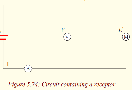
the current I in the circuit.
Questions
a) What is the net electrical power received by the motor?
b) What becomes this power and how is it transformed?
c) What is the relation between the voltage and the back
electromotive force?
d) From the relation found, how do you calculate the intensityof the current flowing?
Application activity 5.4
1. A circuit has in series a generator of emf 6V and internal
resistance 0.1Ω, a receptor of back emf 1.5V and internal
resistance 0.4Ω and a passive resistor of 8.5Ω. Calculate:
a) The intensity of the current flowing in the circuit.
b) The power supply by the generator.c) The quantity of heat produced in the resistor in one minute.
2. A battery has an emf of 12.0V and an internal resistance of 0.05Ω.
Its terminals are connected to a load resistance of 3.00Ω. (a) Find
the current in the circuit and the terminal voltage of the battery.
(b) Calculate the power delivered to the load resistor, the power
delivered to the internal resistance of the battery, and the powerdelivered by the battery.
3. Calculate the terminal voltage for a battery with an internal
resistance of 0.9Ω and an emf of 8.5V when the battery is connectedin series with (a) an 81Ω resistor, and (b) 810Ω.
4. A 9V battery whose internal resistance r is 0.5Ω is connected inthe circuit shown in the figure.
a) How much current is drawn from the source?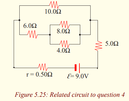
b) What is the terminal voltage of the battery?c) What is the current in the 6Ω resistor?
5. What is the internal resistance of a 12V car battery whose terminal
voltage drops to 8.4V when the starter draws 75A? What is theresistance of the starter?
6. A 1.5V dry cell can be tested by connecting it to a low-resistance
Ammeter. It should be able to supply atleast 22A. What is the
internal resistance of the cell in this case, assuming it is muchgreater than that of the Ammeter?
7. A cell whose terminals are connected to a wire in nickel silver of
resistivity 30 x 10 -6 Ωcm and cross sectional area 0.25mm2
and
length 5m sends a current of 160mA. When the length is reduced
to a half, the intensity of the current is of 300mA. Calculate:
a) The internal resistance.b) The emf of the cell.
8. A cell (E = 1.5V, r = 1.3Ω) sends a current in an external
resistance of 3Ω. Calculate:
a) The intensity of the current in the circuit.
b) The p.d at terminals of the cell.
c) The power of generator.d) The efficiency of the cell.
9. A battery is composed by 120 cells in series. Each element has an
emf of 2V and an internal resistance of 0.001Ω. The combination
is connected to an external resistance of 4.8Ω. Calculate:
a) The intensity of the current in the circuit.
b) The voltage at terminals of the battery.
c) The energy dissipated by joule effect when the currentflows in the circuit in one hour.
Kirchhoff’s rules
Activity 13
Find the equivalent Resistance
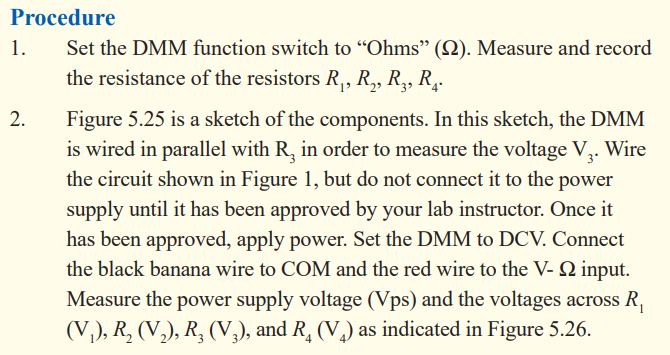
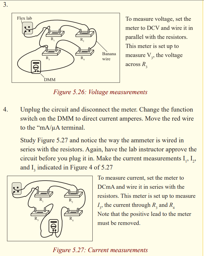
In this experiment you will be using a digital multimeter (DMM) which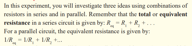
can function as either a voltmeter or an Ammeter.
The voltmeter must always be wired in parallel with the resistor whose
voltage you are measuring. The ammeter, used to measure current, must
always be wired in series. Disconnect the meter from the circuit before
you change the function setting. Failure to follow these procedures can
result in serious damage to the meter. Be sure that you use the correct unitswith your data.
Materials
* 1 multimeter.
* 1 330 Ω or 240 Ω resistor.
* 1 1000 Ω (1KΩ) resistor.
* 1 2000 Ω (2KΩ) resistor.
* 1 3000 Ω (3KΩ) resistor or 1 3300 Ω (3.3KΩ) resistor.
* 1 0- 10K resistor substitution box.
* 2 spade lugs.
* 2 2’ red banana wires.
* 2 2’ black banana wires.* 4 4” black banana wires.
Simple circuits can be analysed using the expression V = IR and the rules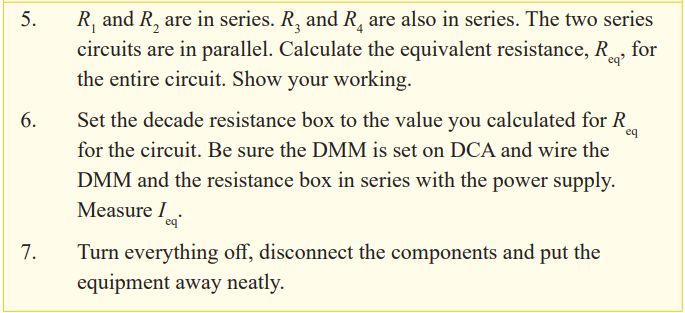
for series and parallel combinations of resistors. Very often, however, it is
not possible to reduce a circuit to a single loop. The procedure for analysing
more complex circuits is greatly simplified if we use two principles calledKirchhoff's rules:
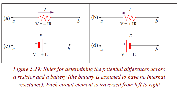
Kirchhoff’s second rule follows from the law of conservation of energy. Let us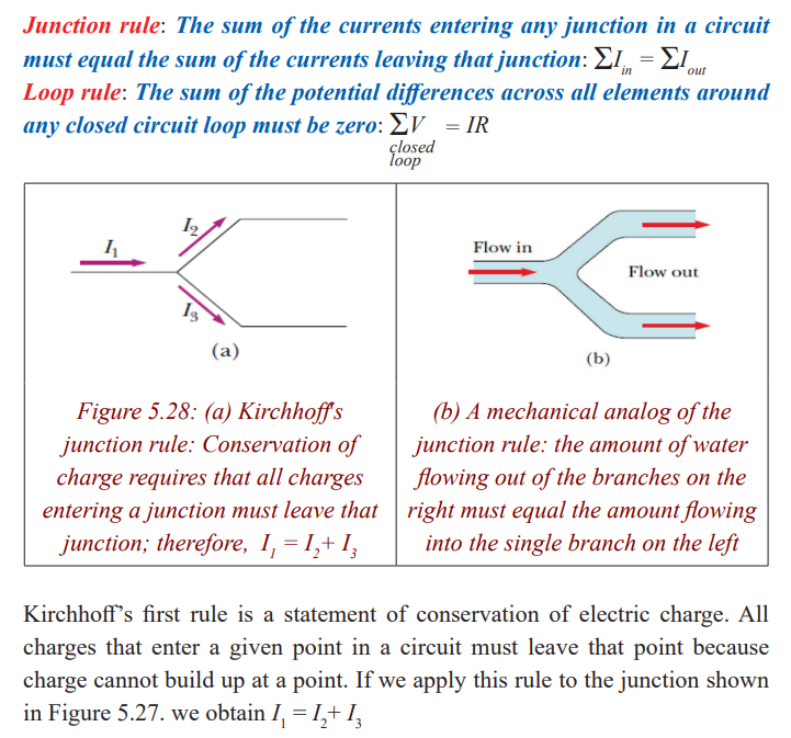
imagine moving a charge around a closed loop of a circuit. When the charge
returns to the starting point, the charge–circuit system must have the same
total energy as it had before the charge was moved. The sum of the increases in
energy as the charge passes through some circuit elements must equal the sum
of the decreases in energy as it passes through other elements. The potential
energy decreases whenever the charge moves through a potential drop -IR
across a resistor or whenever it moves in the reverse direction through a source
of emf. The potential energy increases whenever the charge passes through abattery from the negative terminal to the positive terminal.
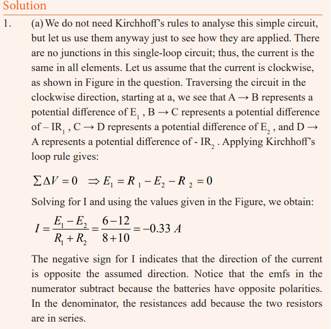
Examples
1. A single-loop circuit contains two resistors and two batteries, as
shown in figure 5.29 (neglect the internal resistances of the batteries).
(a) Find the current in the circuit. (b) What power is delivered toeach resistor? What power is delivered by the 12V battery?

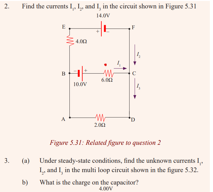
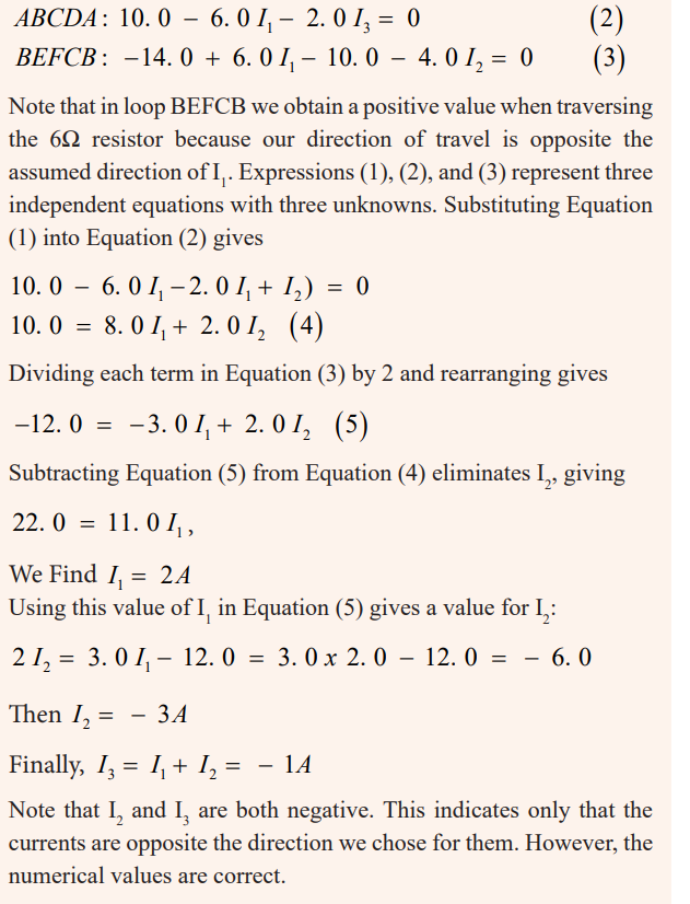
We therefore need only two loop equations to determine the unknown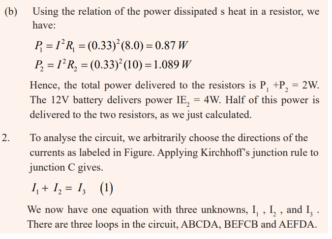
currents. (The third loop equation would give no new information).
Applying Kirchhoff’s loop rule to loops ABCDA and BEFCB andtraversing these loops clockwise, we obtain the expressions
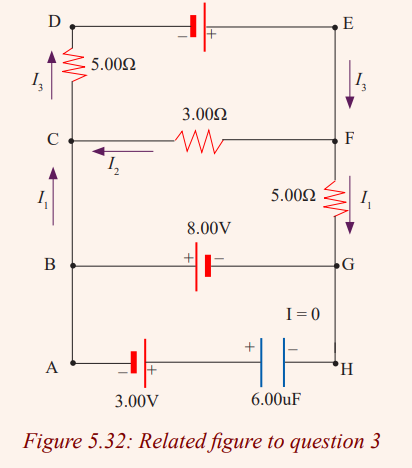
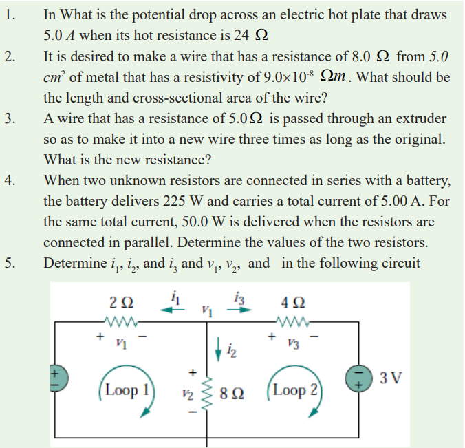
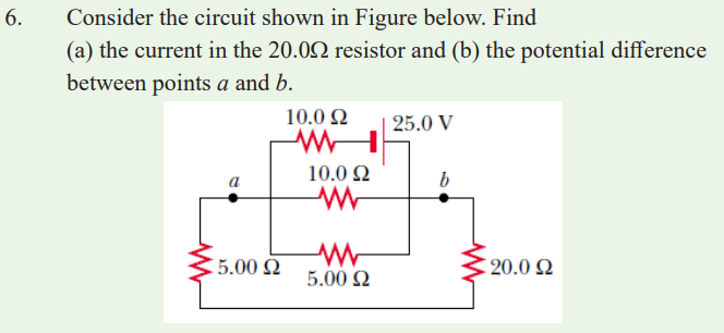
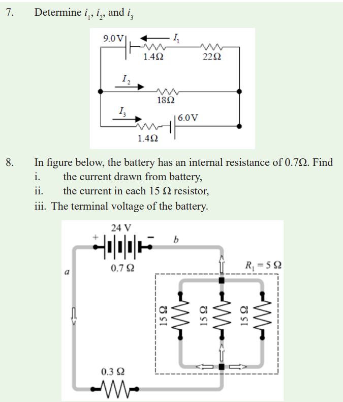
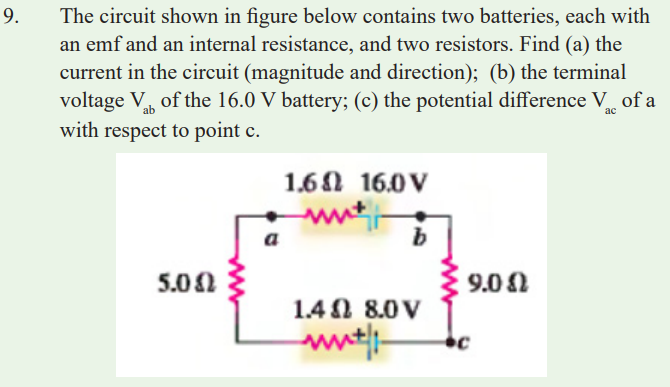
END UNIT ASSESSMENT
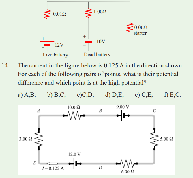
13. A dead battery is charged by connecting it to the live battery of
another car with jumper cables as shown in the figure. Determinethe current in the starter and in the dead battery.