Topic outline
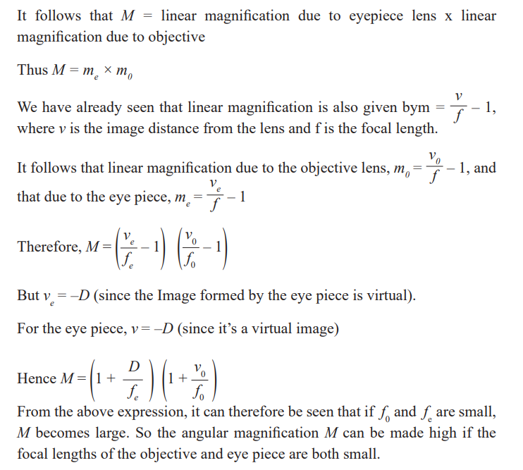
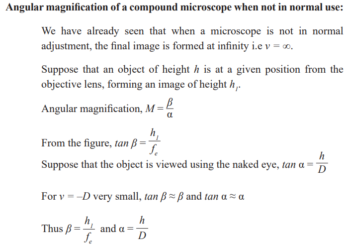
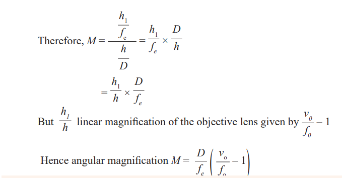
Introduction
Changes in schools
This text book is part of the reform of the school curriculum in Rwanda: that is
changes in what is taught in schools and how it is taught. It is hoped this will
make what you learn in school useful to you when you leave school, whateveryou do then.
In the past, the main thing in schooling has been to learn knowledge – that is
facts and ideas about each subject. Now the main idea is that you should be
able to use the knowledge you learn by developing skills or competencies.
These skills or competencies include the ability to think for yourself, to be
able to communicate with others and explain what you have learnt, and to be
creative, that is developing your own ideas, not just following those of the
teacher and the text book. You should also be able to find out information and
ideas for yourself, rather than just relying on what the teacher or text booktells you.
Activity-based learning
This means that this book has a variety of activities for you to do, as well
as information for you to read. These activities present you with material or
things to do which will help you to learn things and find out things for yourself.
You already have a lot of knowledge and ideas based on the experiences you
have had and your life within your own community. Some of the activities,therefore, ask you to think about the knowledge and ideas you already have.
In using this book, therefore, it is essential that you do all the activities.
You will not learn properly unless you do these activities. They are the mostimportant part of the book.
In some ways this makes learning more of a challenge. It is more difficult to
think for yourself than to copy what the teacher tells you. But if you take up
this challenge you will become a better person and become more successfulin your life.
Group work
You can also learn a lot from other people in your class. If you have a problem
it can often be solved by discussing it with others. Many of the activities in the
book, therefore, involve discussion or other activities in groups or pairs. Your
teacher will help to organise these groups and may arrange the classroom so
you are always sitting in groups facing each other. You cannot discuss properlyunless you are facing each other.
Research
One of the objectives of the new curriculum is to help you find things out
for yourself. Some activities, therefore, ask you to do research using books
in the library, the internet if your school has this, or other sources such as
newspapers and magazines. This means you will develop the skills of learning
for yourself when you leave school. Your teacher will help you if your schooldoes not have a good library or internet.
Icons
To guide you, each activity in the book is marked by a symbol or icon to showyou what kind of activity it is. The icons are as follows:

Unit 1 :Thin lenses

Key unit Competence
Explain the properties of lenses and image formation by lenses.
My goals
By the end of this unit, I will be able to:
* explain physical features of thin lenses
* state the types of lenses and explain their properties
* differentiate between lenses and curved mirrors
* explain the phenomenon of refraction of light by lenses
* construct the ray diagrams for formation of images by lenses
* explain the defects of lenses and how they can be corrected* describe the daily applications of lenses
INTRODUCTORY ACTIVITY
Using a hand lens, candle (object) and a plain paper (screen).
• Light the candle
• Place the candle hand lens and plain paper on the same line respectively
• Variate the position of the hand lens and sees the variation of the imageon the screen.
Questions
1. Discuss on the image formed on the screen (nature).
2. Try to draw a ray diagram of your observation and then discuss the
properties of the hand lens.
3. Discuss on the changes of your observation on the screen that are taking
place as you variate the positions of the hand lens.4. Discuss other types of lenses and brainstorm their different uses.
Introduction
The scientific study of light and optical material is involved in the making of
spectacles, cameras, projectors and optical instrument.
The most important optical materials are the various kinds of glass, but
many others such as plastics, polaroid, synthetics and natural crystals have
increasingly useful application.
In this unit we shall consider the behavior of certain component of lenses andits images formation.
Observe and think
Look at yourself in a flat mirror and choose one of the following that identifies
your observation;
a) my image is clearly seen without changes.b) my image shows some changes.
What do you think
a) What do you think about formation of your image by the mirror?b) What are the characteristics of this image formed?
Key conceptImage formation through a mirror.
Discovery activity
a) Look through a plain glass window and observe what happens. Discuss
with your neighbor on what is observed.
b) Look through an open window and discuss with your neighbor about the
observations.
c) Compare the observations in part (a) and (b) above.d) Look through the lenses and describe the nature of image formed.
What I discover
Just curved mirrors change images, certain transparent medium called lensalter what you see through them.
A lens is a transparent medium (usually glass) bound by one or two curved
surfaces. Different lenses give various natures of images depending on theircharacteristics.
Types of lenses and their characteristics
A lens is a piece of glass with one or two curved surfaces. The lens which is
thicker at the centre than at the edges is called a convex lens while the one
which is thinner at its centre is known as a concave lens. The curved surface of
the lens is called a meniscus. The lens in the human eye is thicker in the centre,and therefore it is a convex lens
Activity 1
Required Materials
• Notebook
• 2 convex lenses
• 2 concave lenses
• Flashlight or a torch bulb
• White paper
Procedure
1. Look closely at the lenses and answer these questions in your notebook:
a. How are the lenses shaped?
b. How are the lenses alike?
c. How are the lenses different?
2. Look through the lenses at the pages of a book, your hands, a hair,
and other things. Draw what you see in your notebook and label each
picture with the type of lens with which you observed the object. Be
sure to answer the following questions:
a. How does a concave lens make things look like?
b. How does a convex lens make things look like?
3. Lenses bend light in different directions. Shine a flashlight through
the lenses onto a piece of white paper and then answer the following
questions in your notebook:
a. In what direction do convex lenses bend light?
b. In what direction do concave lenses bend light?
4. Shine the flashlight through different combinations of lenses: two
convex lenses, two concave lenses, one concave and one convex lens.
Draw pictures of what you see and answer these questions:
a. What happens when you use multiple lenses at the same time?
b. Can you use two different lenses to make things far away appear
closer?
5. If you can, darken the room and place a convex lens between a sunlit
window and a white piece of paper. Place the lens close to the paper
and then slowly move the lens towards the window. Draw a picture of
what you see in your science notebook.
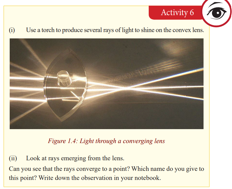
Do you see that rays change the direction after the lens? How do the emergentrays from each of the lenses behave?
The light rays from the ray box change the direction after passing through the
lens. They are therefore refracted by the lens. Hence, lenses form images ofobjects by refracting light.
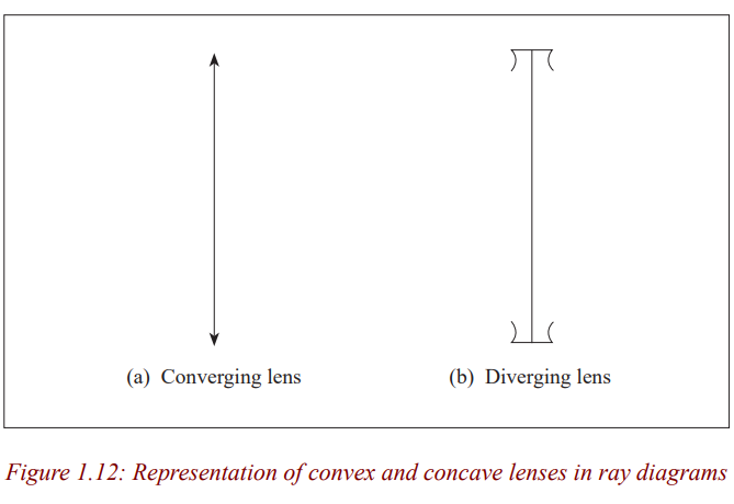
You can see that the rays from the convex lens are getting closer and closer
to a point. The rays are thus converging, and hence a convex lens is called a
converging lens. You can also see that the refracted rays from the concave lensare spreading out. This kind of lens is called diverging lens.
Summary:
1. A lens is a transparent medium (usually glass) bounded by one or two
curved surfaces. There are two types of lenses; a convex lens also called aconverging lens and a concave lens also known as a diverging lens.
2. A convex lens is the one which is thicker at the centre than at the edges. A
concave lens is the one which is thinner at the centre than at the edges.
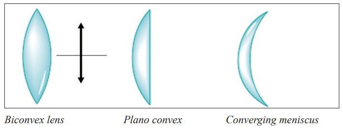
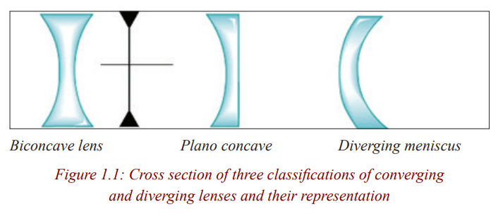
The figure below shows three classifications of convex lenses and threeclassifications of concave lenses.
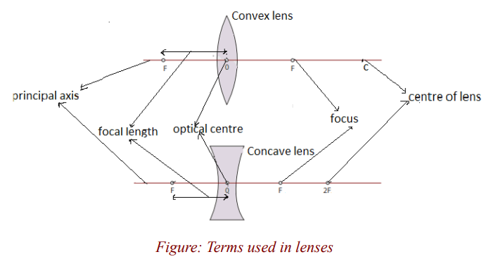
Terms used in lenses
Lenses have two lines of symmetry, a vertical line and a horizontal line. The
vertical line is called the axis of the lens (already seen in activity 2). Thehorizontal line is known as the principal axis of the lens.
Notice that these lines meet at a point. This point is the centre of the lens,called the optical centre of the lens denoted by O.
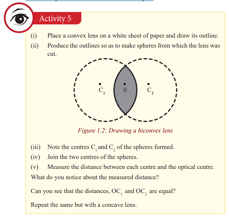
The centre of each sphere is called the centre of curvature of the surface of a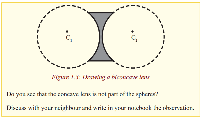
lens and the distance from the centre of curvature to the optical centre is the
radius of curvature of the surface. Since the convex lens forms part of thespheres, its centre of curvature is real and hence its radius of curvature.
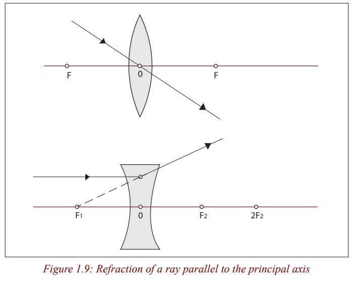
This point to which all parallel rays converge after refraction by a convex lens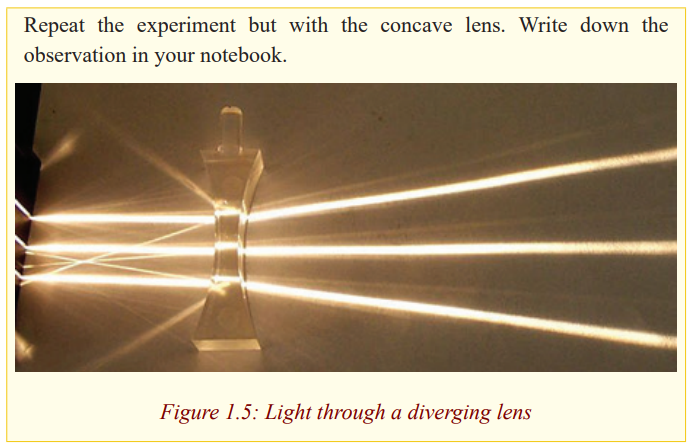
is called the principal focus of the convex lens.
The rays emerge from the lens when they are spreading out. They are diverged
and appear to come from a point. This point from which the rays appear todiverge after refraction by the concave lens is the principal focus of the lens.
Since rays converge to this point for the case of a convex lens, the principal
focus of a convex lens is real. The principal focus of a concave lens is virtualas the rays appear to come from it.
Repeat the above experiments by changing the lenses so that their right sidesbecome the left.
Do you see that the same thing happens for each?
Light can travel into the lens from the left or from the right. It therefore hastwo principal foci on both sides of the lens.
The principal focus of a lens is also called the focal point of the lens, and it isdenoted by F.
Since the image forms where the refracted rays meet and because the rays from
the distant tree are parallel, the piece of paper must then be at the principal
focus of the lens. This distance from the lens to the image is the focal length
of the lens. The focal length of the lens is thus the distance from the centre ofthe lens to the principal focus. It is always denoted by f.
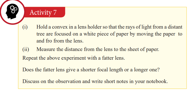
The fatter lens has a shorter focal length, implying that the thicker the lens, theshorter the focal length and vice versa.
We have already seen that the lens has two principal foci. It means that theseprincipal foci are at equal distances on the opposite sides of the lens.
Repeat the experiment with the concave lens.
What do you notice?
The image cannot be seen. This is because the concave lens has a virtualprincipal focus.
Refraction of light through lenses
Lenses can be thought of as a series of tiny refracting prisms, each of which
refracts light to produce an image. These prisms are near each other (truncated)and when they act together, they produce a bright image focused at a point.
Each section of a lens acts as a tiny glass prism. The refracting angles of these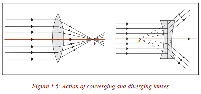
prisms decrease from the edges to its centre. As a result, light is deviated moreat the edges than at the centre of the lens.
The refracting angles of the truncated prisms in a converging lens point to theedges and so bring the parallel rays to a focus.
The truncated prisms of the diverging lens point the opposite way to those of
the converging lens, and so a divergent beam is obtained when parallel rays
are refracted by this lens because the deviation of the light is in the oppositedirection.
The middle part of the lens acts like a rectangular piece of glass and a rayincident to it strikes it normally, and thus passes undeviated.
Properties of images formed by lenses
Rays come from all points on the objects. Where these rays meet or appear to
meet after refraction by the lens is the position of the image.
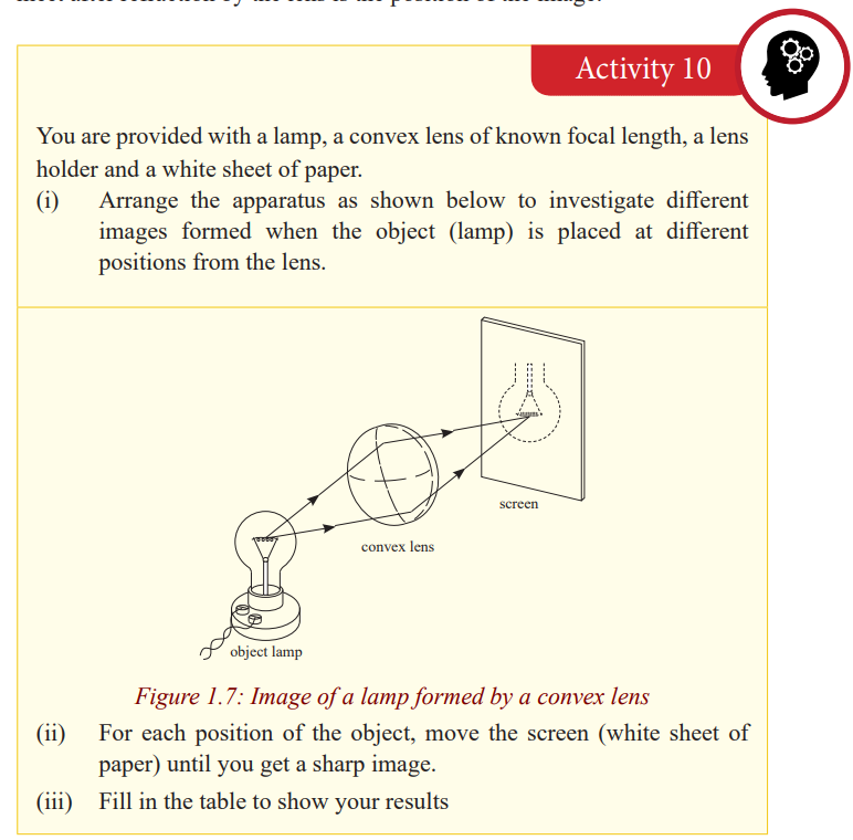
Notice that an image cannot be seen on the screen irrespective of the position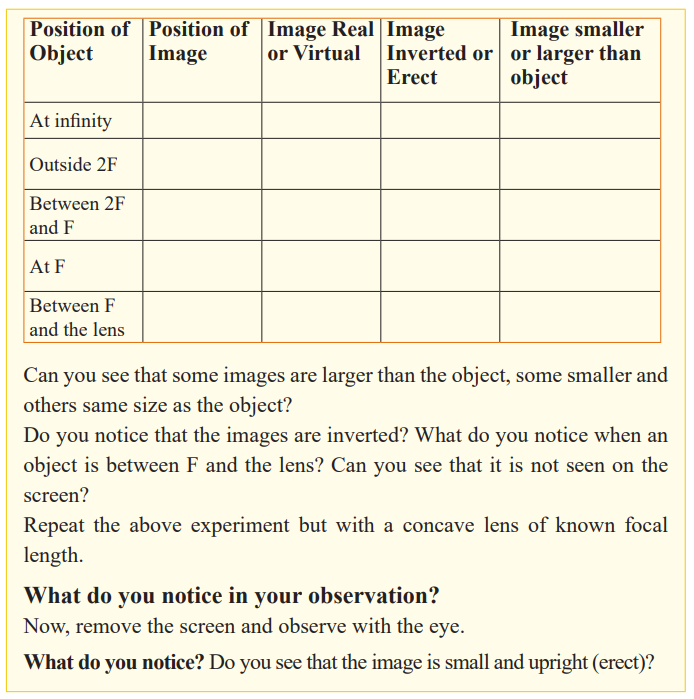
of the object. The nature of the image formed by a convex lens depends on theposition of the object along the principal axis of the lens.
The principal focus of a lens plays an important part in the formation of an
image by a lens since parallel rays from the object converge to it, and thus,
we consider points F and 2F when describing the nature of the images formed
by the lens. These images can be larger or smaller than the object or same
size as the object. When an image is larger than the object, we say that it is
magnified and when it is smaller, we say that it is diminished. Images which
can be formed on the screen are Real images. Because light rays pass through
these images, real images can be formed on the screen. All real images formedby the convex lens are inverted.
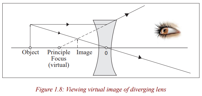
When an object is between F and the lens, there is no image formed on the
screen. The image formed is not real and is only seen by removing the screen
and placing an eye in its position. We say that it is a virtual image. For a
virtual image, rays appear to come from its position. Unlike for a convex lens
where the nature of the image depends on the position of the object, a concave
lens gives only an upright, small, virtual image, and is situated between theprincipal focus and the lens for all positions of the object.
Critical thinking:
1. Design an experiment to study images formed by convex lenses of
various focal lengths. How does the focal length affect the position and
size of the image produced?
2. Suppose you wanted to closely examine the leaf of a plant, which typeof a lens would you use? Explain your decision.
Ray diagrams and properties of images formed by lenses
We have already seen that an image is formed where rays from the object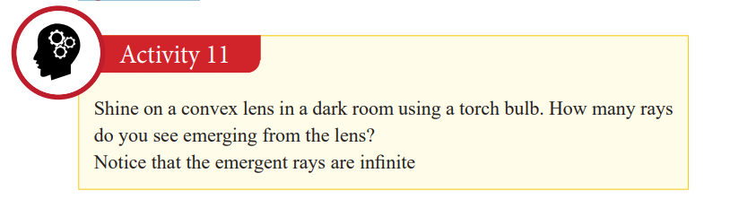
meet. Rays come from all points on the objects. However, for simplicity, only
a few rays from one point are considered when drawing ray diagrams. Where
these rays meet or appear to meet after refraction by the lens is the position ofthe image.
To locate the position of the image, two of the following three rays are
considered.
1. A ray parallel to the principal axis which after refraction passes throughthe principle focus or appears to come from it.
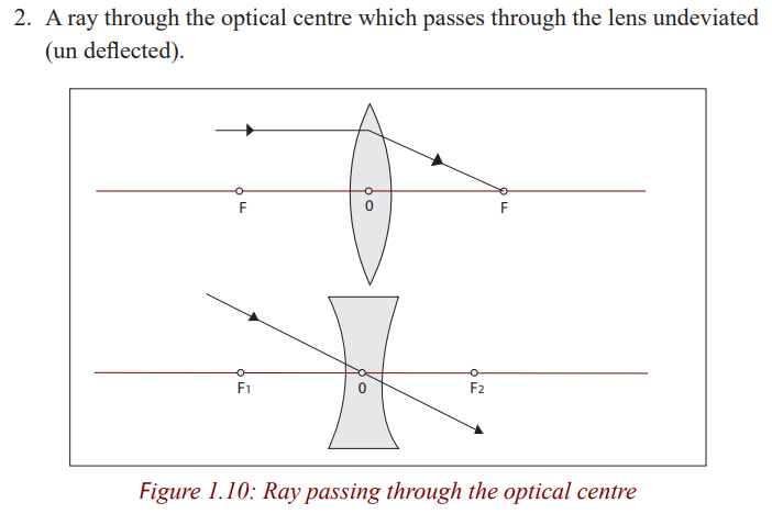
The central part of a lens acts as a small parallel –sided block which slightly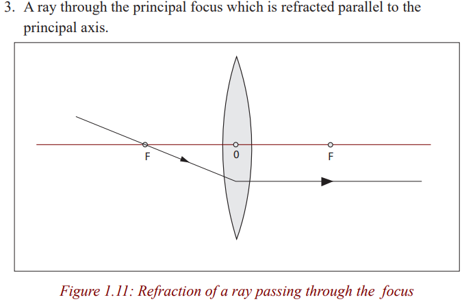
displaces but does not deviate a ray passing through it and for a thin lens, thedisplacement can be ignored.
In ray diagrams, a thin lens is represented by a straight line at which all the
refraction is considered to occur. In reality, bending takes place at each surfaceof the lens.
Ray diagrams for a convex lens
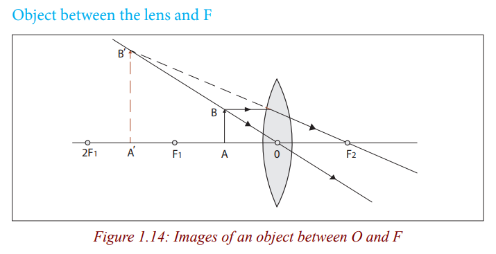
Nature of imageThe image is virtual, erect, larger than the object and behind the object.
Application activity 1.1How is this lens useful when the object is in this position?
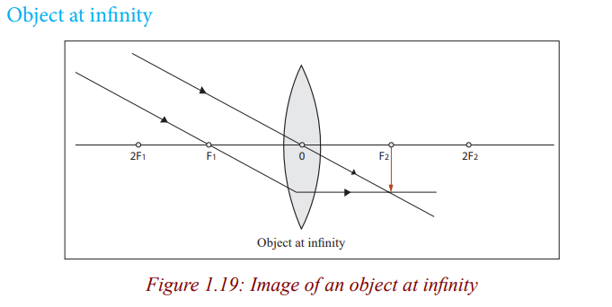
Nature of image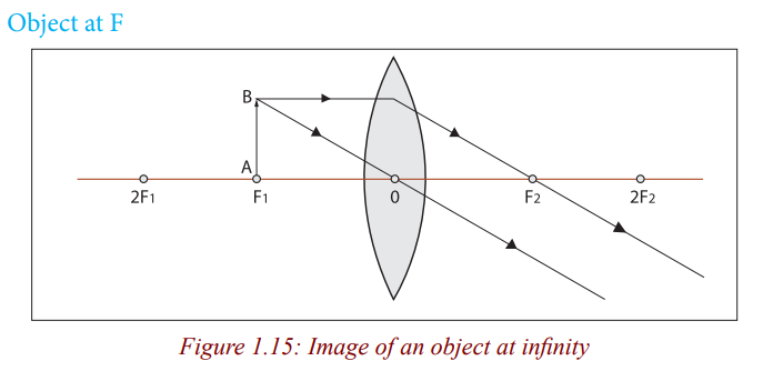
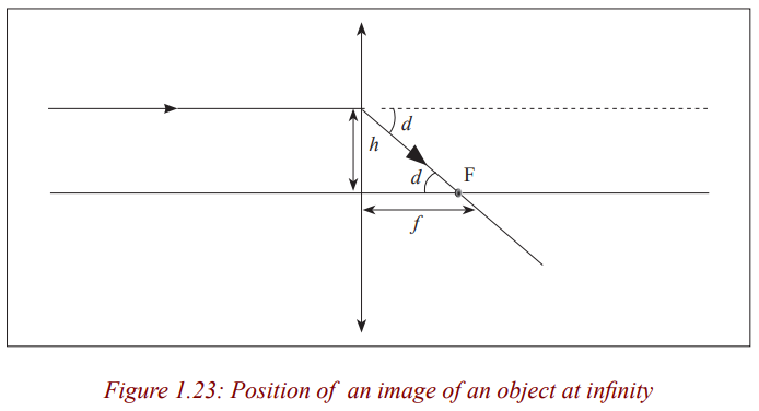
The image is formed at infinity.
Application activity 1.2
Can you think of how useful is the lens when an object is at its focal point?What is it?
Nature of image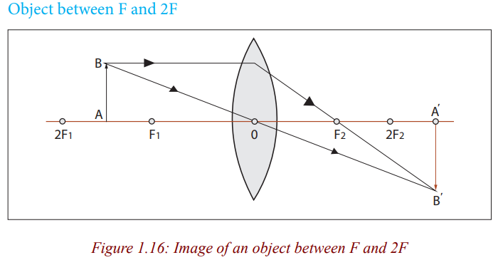
The image is real, inverted, larger than object (magnified) and beyond 2F.
Application activity 1.3How is the lens useful when the object is in the above position?
Nature of image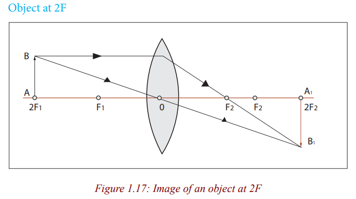
The image is real, inverted and same size as object.
The image is real, inverted, smaller than object (dimensional) and is formed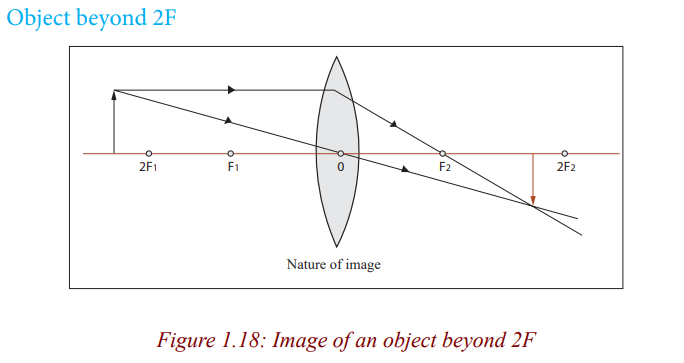
between F and 2F.
Application activity 1.4
What can be a daily application of the lens when an object is in thisposition?
Nature of image
The image is real, inverted, smaller than object and is formed at F.
When an object is between the lens and the principal focus, the rays from the
object never converge, instead they appear to come from a position behind
the lens. In this case, the lens is used as a simple magnifying glass because itforms an upright and magnified image (Figure 1.14).
When an object is at the principal focus of the lens, refracted rays emerge from
the lens parallel to each other, and the lens is used as a search light torch, andtheatre spotlights (Figure 1.15).
Figure 1.16 shows that when an object is between F and 2F, the lens forms amagnified real image. In this case, a lens is used as a film projector.
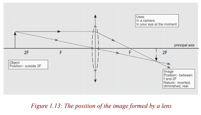
When an object is beyond 2F (Figure 1.18), a lens forms real and small image.
The lens is used as a camera because this small, real image can be formed ona piece of film.
Ray diagrams for a concave lens
Accurate construction of ray diagrams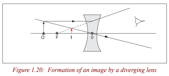
Problems for locating the position of the image can be solved by constructinga ray diagram as an accurate scale drawing on a graph paper.
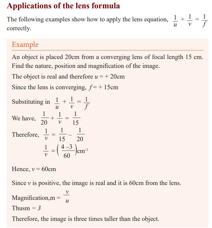
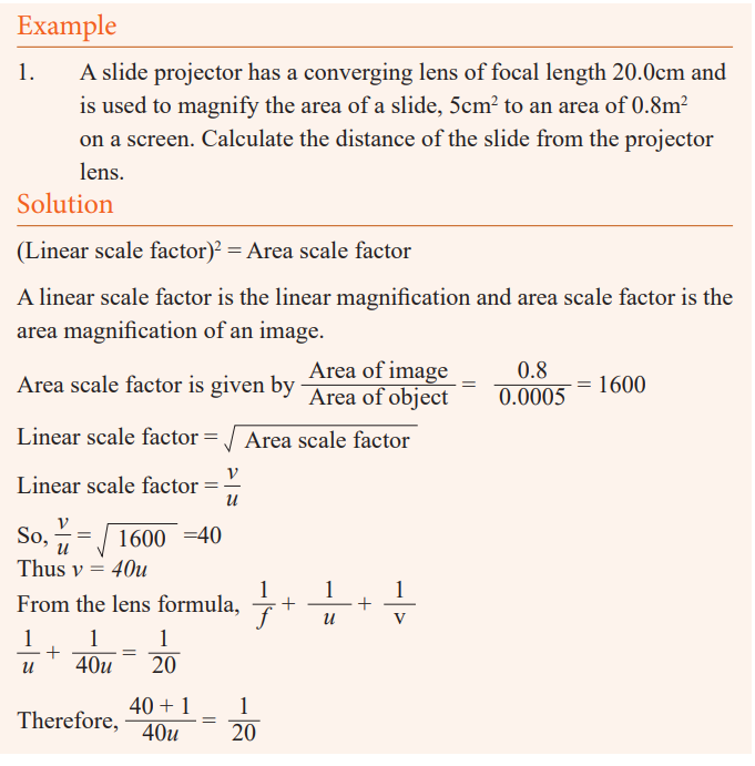
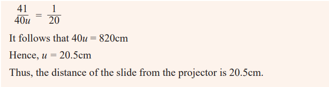
Example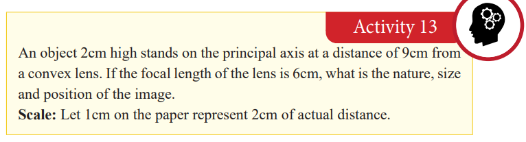
1. An object is placed 40 cm away from a diverging lens of focal length
20cm. If it is 2 cm high, determine graphically the position, size and
nature of the image.
2. Let 1cm on the paper represent 10 cm on the horizontal axis and 1cmon the vertical axis of the actual distance.
The image is virtual, erect, 0.7cm tall and is formed at 13cm from the lens on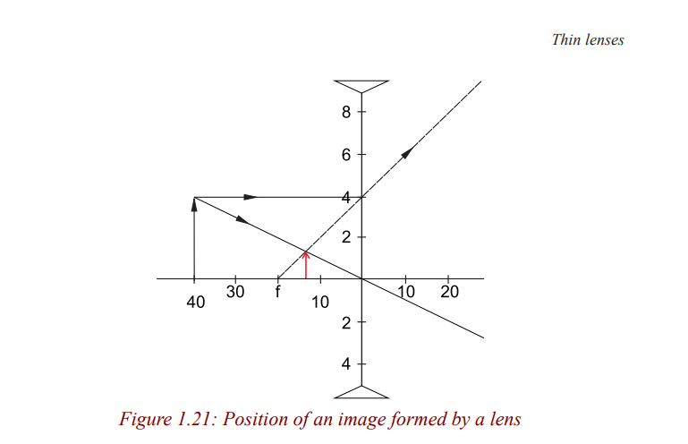
the same side as the object.
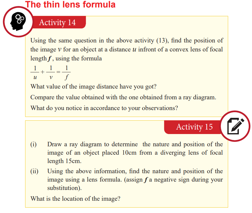
The thin lens formula
The sign convention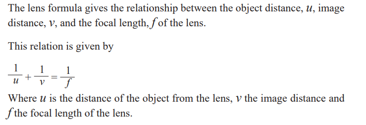
From activity 13, we notice that all the distances are measured from the
optical centre and in activity 14, we substituted for u, v and f using positive
numerical values. It therefore follows that distances of real images and realprincipal focus are positive.
In activity 14, then you will notice that the image distance from the lens is
negative but equal to the distance determined graphically. This distance is
obtained by using a negative numerical value of the focal length. Since a
concave lens has a virtual principal focus, and forms virtual images, distances
of virtual images and virtual principal foci are negative. Sign convention
states that real is positive while virtual is negative. This should be put underconsideration when one is using the lens formula to solve problems.
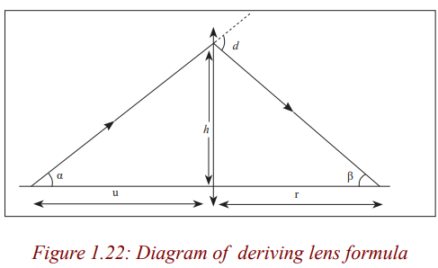
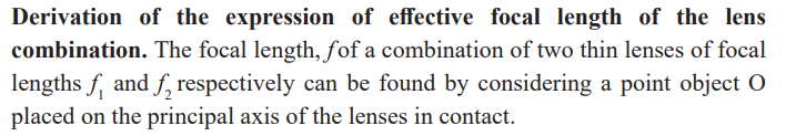
Derivation of the lens formula
Convex lens
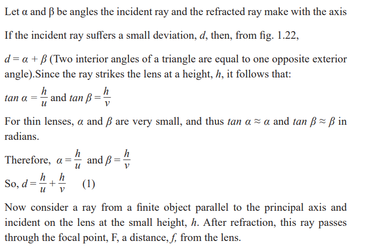
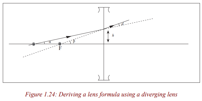
Consider a point object O on the principal axis, at a distance, u greater than thefocal length from the lens.
Suppose that a ray from O is incident on the lens at a small height h above theaxis and is refracted to form an image I at a distance v from the lens.
Concave lens
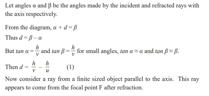
Consider a point object O on the principal axis of the diverging lens at adistance, u, so that its image is formed at a distance, v.
Application activity 1.5
1. An object is placed 12cm from a converging lens of focal length 18
cm. Find the nature and the position of the image.
2. Find the nature and position of the image of an object placed 15cmfrom a diverging lens of focal length 15cm.
Critical thinking exercise
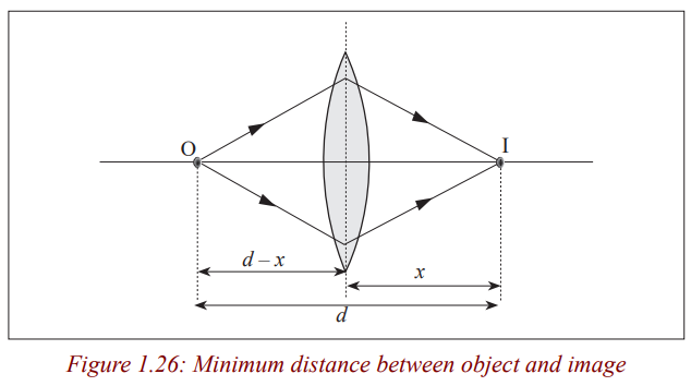
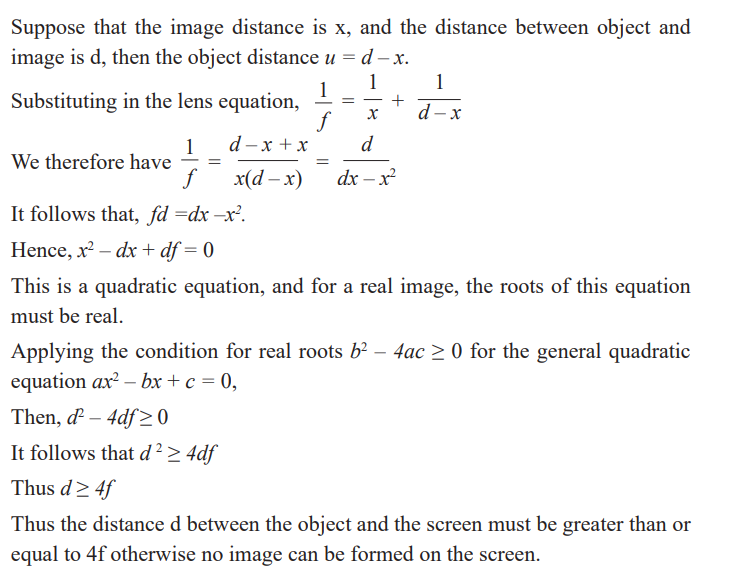
Least possible distance between object and real image with converging lens
Experiments show that it is not always possible to obtain a real image on a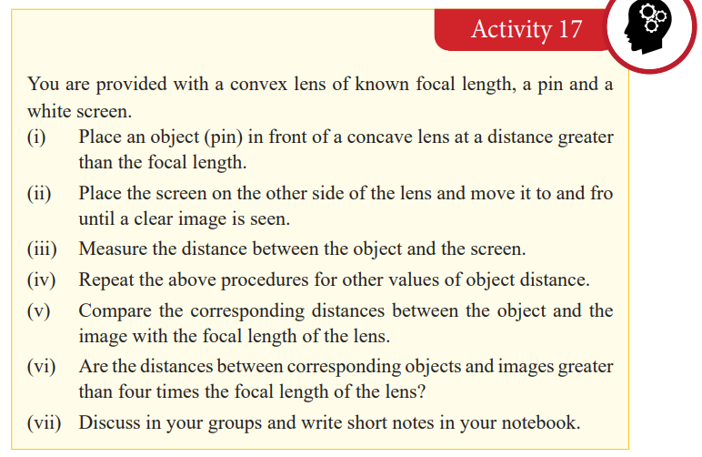
screen although the object and the screen may both be at a greater distance
from a converging lens than its focal length. Theory shows that the minimum
distance between the object and the screen for an image to be formed is four
times the focal length, f. Therefore, the distance between an object and ascreen must be equal to or greater than four times the focal length.
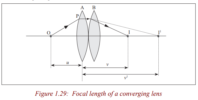
Consider a point object O on the principal axis of a converging lens forming an image I.
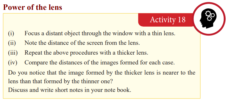
Since the image formed by the thicker lens is nearer, the thicker lens is more
powerful than the thinner lens of the same material. We have already seen that
an image of a distant object forms at the focus of the lens and the thicker the
lens the shorter the focal length. So the power of the lens depends on its focal
length, that is, as the focal length becomes shorter, the power increases. Thepower of the lens is defined as the reciprocal of its focal length in metres.
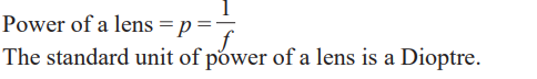
Application activity 1.6
1. Calculate the power of the lens of focal length of 15 cm.2. A converging lens has a power of 0.02D, what is its focal length?
Determination of the focal length of the lens
Converging lens
Rough method
The distance from the lens to the screen is the focal length of the lens since
rays from a distant object strike the lens when they are parallel.
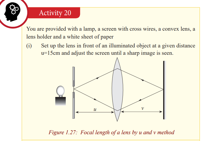
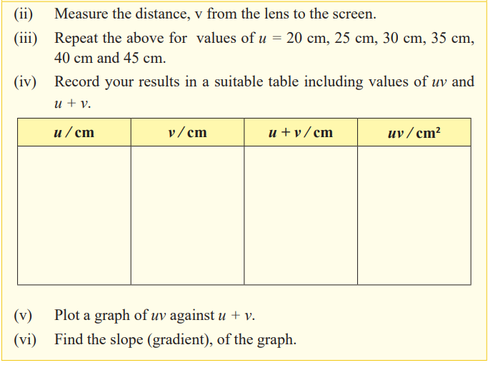
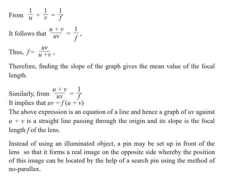
Graphical determination of focal length of a convex lens
Diverging lens
Determination of focal length of a diverging lens by Concavemirror method
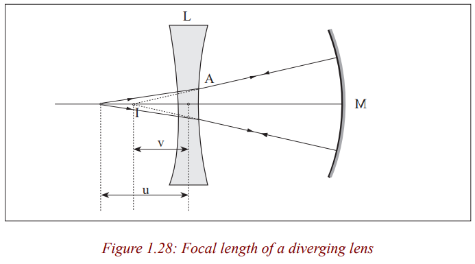
We have already seen that a concave lens forms virtual images of real images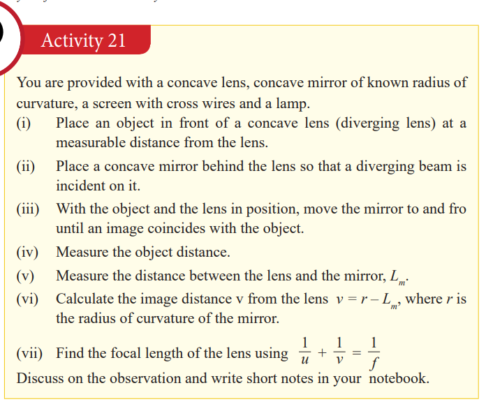
which cannot be seen on the screen. So, to determine the focal length of a
diverging lens, we need to form a virtual object for the diverging lens so that
a real image is produced. This is achieved in the experiment by putting a
concave mirror behind the lens so as to reflect back the diverging rays fromthe lens.
As you saw in your lower secondary classes, when an object is placed at the
principal focus of a concave mirror, the image is formed at the same position
with it. Now, since the object and its image are coinciding, it means that they
are at the centre of curvature of the mirror; v is negative as I is a virtual image
for the lens, and as the object and image are coincident, the rays must be
incident normally on the mirror M. Thus, reflected rays from the mirror passthrough its centre of curvature which is the position of the virtual image.
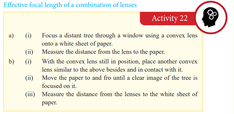
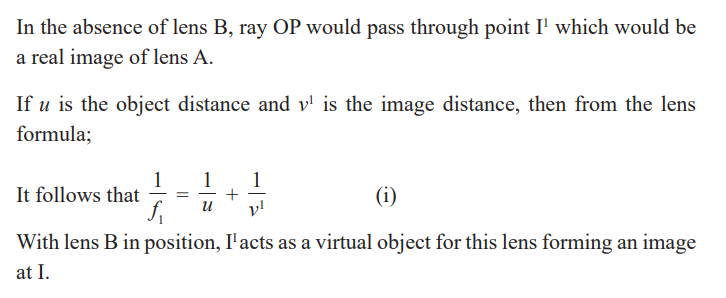
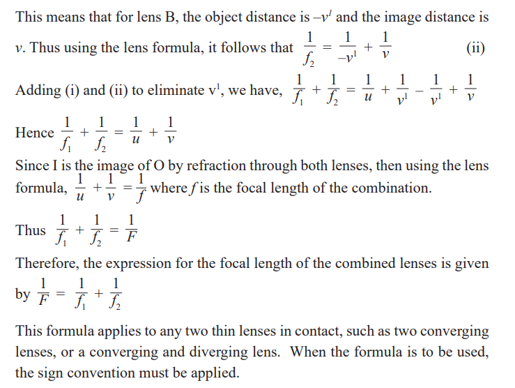
Combination of lenses
In our next unit, we shall talk about instruments which use lenses to focus
objects. Among others, a microscope uses a combination of two lenses tofocus objects.
Application activity 1.7
1. An object O is placed 12cm from a thin converging lens P of focal
length 10cm and an image is formed on a screen S on the other side of
the lens. A thin diverging lens, Q is now placed between the converting
lens and S, 50cm from the converging lens. Find the position and
nature of the final image if the focal length of the diverging lens is15cm.
2. An object is placed 6.0cm from a thin converging lens A of focal
length 5.0cm. Another thin converging lens B of focal length 15cm is
placed co-axially with A and 20cm from it on the side way from theobject. Find the position, nature and magnification of the final image.
Defects of lenses and their corrections
Notice that the image has coloured patches. This defect where by an image
formed has coloured patches is called chromatic aberration.
There are two kinds of defects; spherical aberration and chromatic aberration.
Spherical aberration
This arises in lenses of larger aperture when a wide beam of light incident on
the lens, not all rays are brought to one focus. As a result, the image of the
object becomes distorted. The defect is due to the fact that the focal length
of the lens for rays far from the principal axis are less than for rays closer to a
property of a spherical surface and as a result, they converge to a point closerto the lens.
This defect can be minimised (reduced) by surrounding the lens with an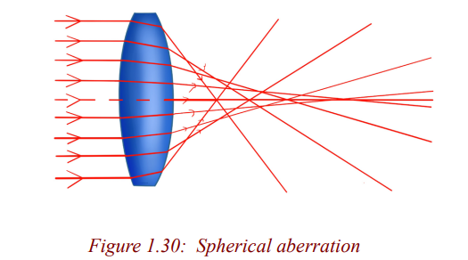
aperture disc having a hole in the middle so that rays fall on the lens at a point
closer to its principal axis. However, this reduces the brightness of the imagesince it reduces the amount of light energy passing through the lens.
Chromatic aberration
This occurs when white light from an object falls on a lens and splits it into its
component colours. These colours separate and converge to different foci, andthis results into an image with coloured edges.
The separation takes place because the material of a glass of a lens has different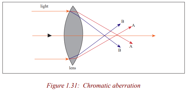
refractive indices for each colour. The colours travel at different speeds in
glass: red colour with the greatest and the violet with the least. As a result,violet is deviated most and red is the least deviated
Thus, a converging lens produces a series of coloured images of an extendedwhite object as shown in the figure above (exaggerated for clarity).
Chromatic aberration can be minimised by using an achromatic lens called an
achromatic doublet. This consists of a converging lens of crown glass combinedwith a diverging lens of flint glass cemented together with Canada balsam.
The flint glass of the diverging lens produces the same dispersion as the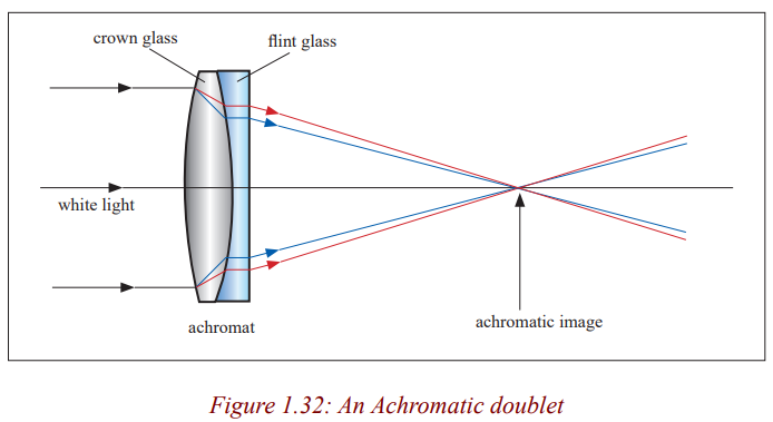
crown glass of the converging lens but in the opposite direction and the
overall combination is converging. As a result, the achromatic combinationconverges the white light to one focus.
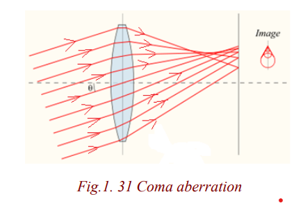
Coma aberration
Another type of aberration is coma, which derives its name from the comet-like
appearance of the aberrated image. In general, a bundle of parallel rays
passing through the lens at a fixed distance from the centre of the lens arefocused to a ring-shaped image in the focal plane, known as a comatic circle.
The sum of all these circles results in a V-shaped or comet-like flare. As with
spherical aberration, coma can be minimized by choosing the curvature of the
two lens surfaces to match the application. Lenses in which both sphericalaberration and coma are minimized are called best form lenses.

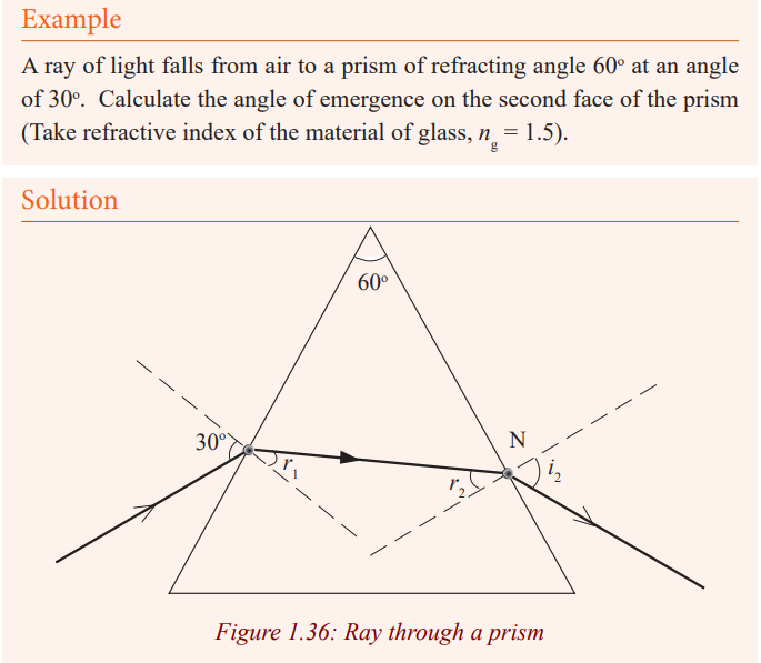
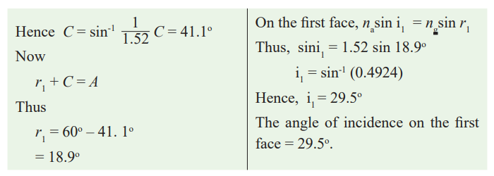
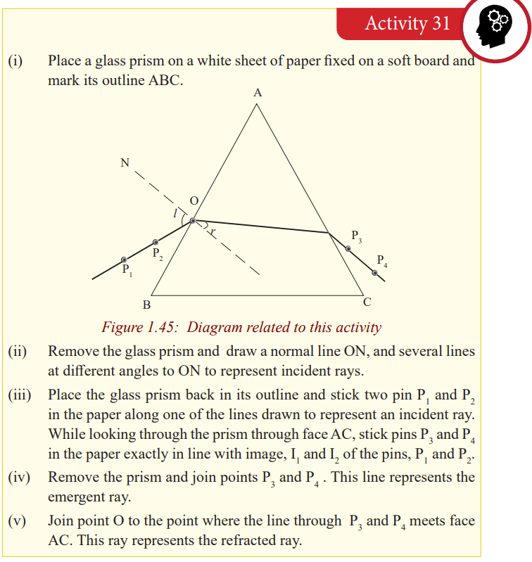
Refraction through prisms
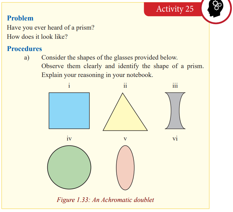
In optics, a prism is transparent material like glass or plastic that refracts light.
Atleast two of the flat surfaces must have an angle less than 90o between them.The exact angle between the surfaces depends on the application.
Terms associated with refraction through prism
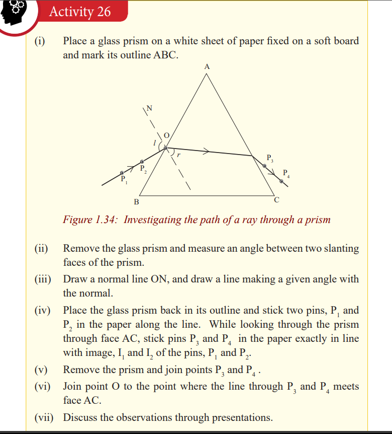
The position and shape of the third side of the prism does not affect the
refraction under consideration and so is shown as an irregular in Fig.
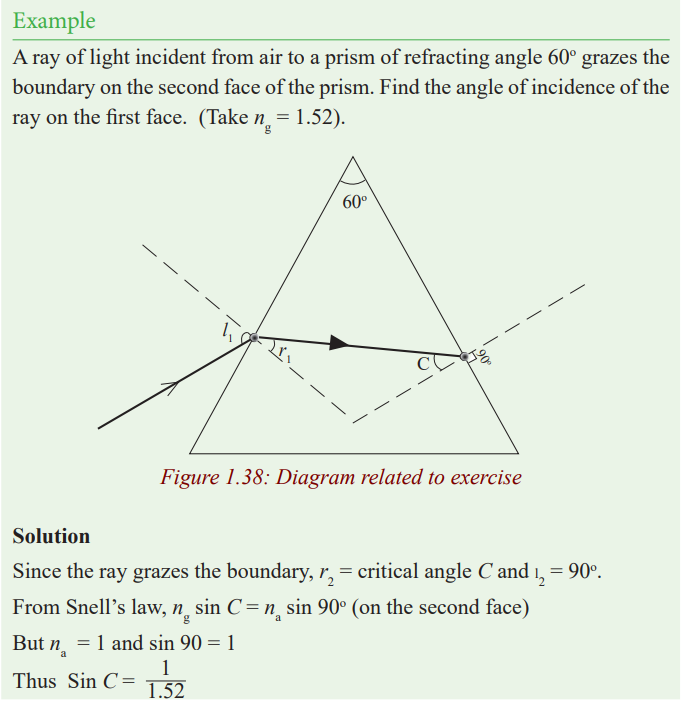
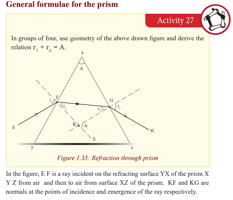
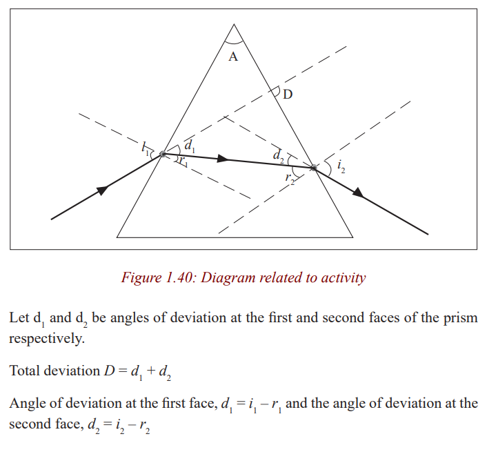
Deviation of light by a prism
Light can be deviated by reflection and refraction. Since a prism refracts light,
it therefore changes its direction.
A prism deviates light on both faces. These deviations do not cancel out as in a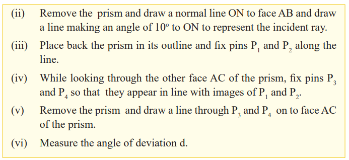
parallel sided block where the emergent ray, although displaced, is parallel to
the incident ray surface. The total deviation of a ray due to refraction at both
faces of the prism is the sum of the deviation of the ray due to refraction at thefirst surface and its deviation at the second face.
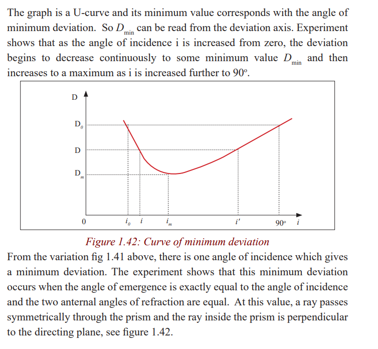
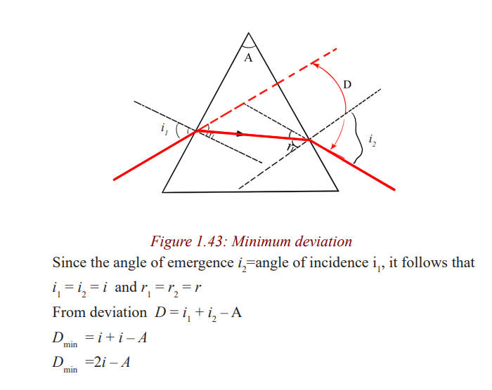
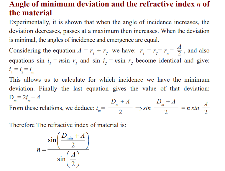
Angle of minimum deviation and determination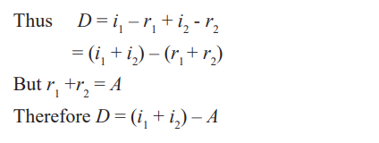
of refractive index n of a material of the prism
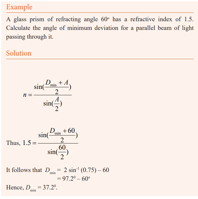
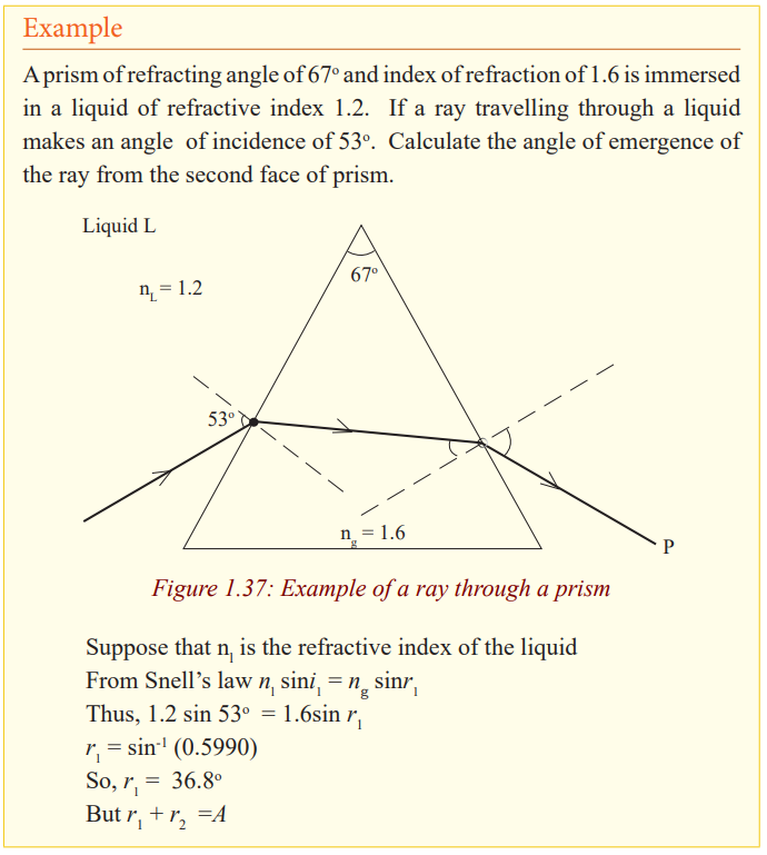
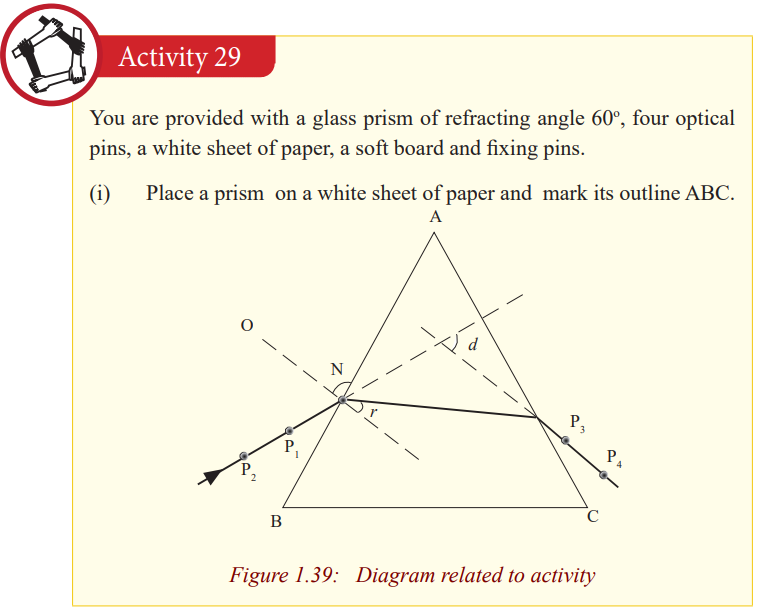
Application Activity 1.8
A glass prism of refracting angle 72o
and index of refraction 1.66 is immersed
in a liquid of refractive index 1.33. What is the angle of minimum deviationfor a parallel beam of light passing through the prism?
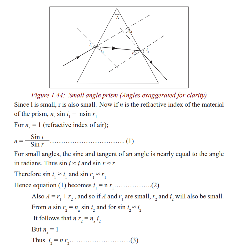
Deviation of light by a small angle prism
Consider a ray incident almost normally in air in a prism of small refracting
angle A (less than about 60 or 0.1 radian) so that the angle of incidence i issmall.
The expression D = A (n – 1) shows that for a given angle A, all rays entering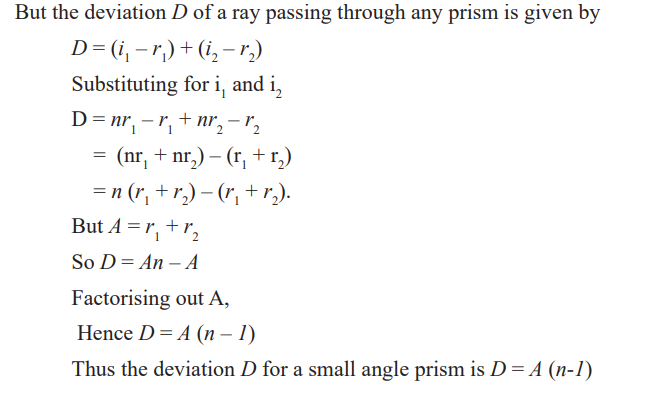
a small angle prism at small angles of incidence suffer the same deviation.
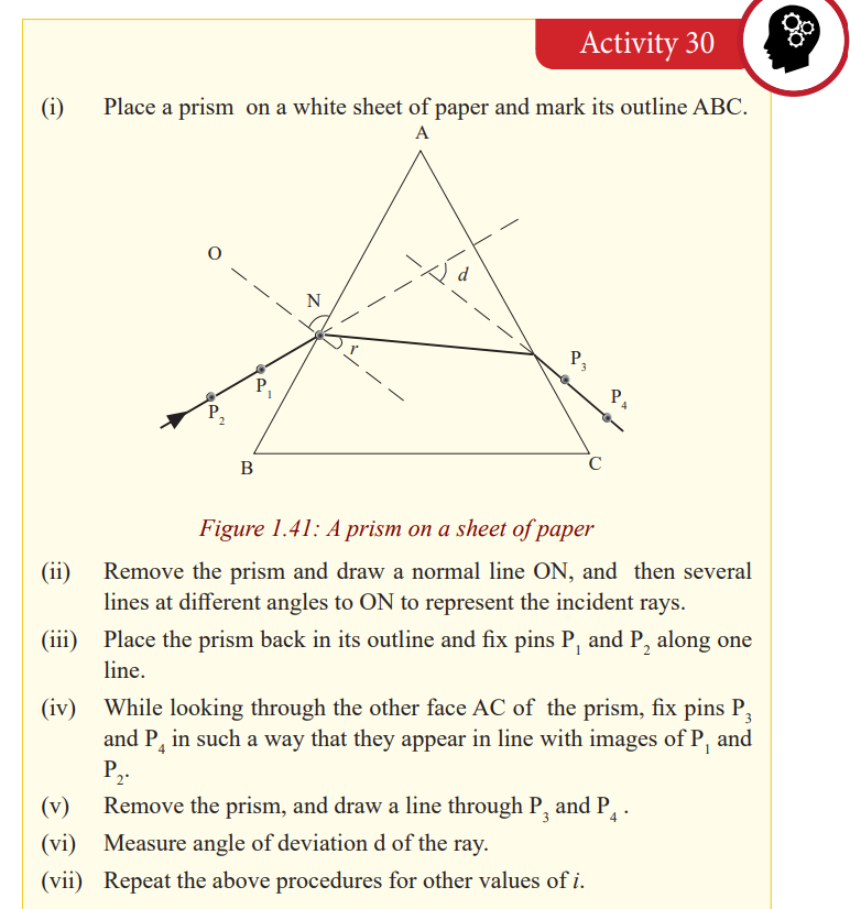
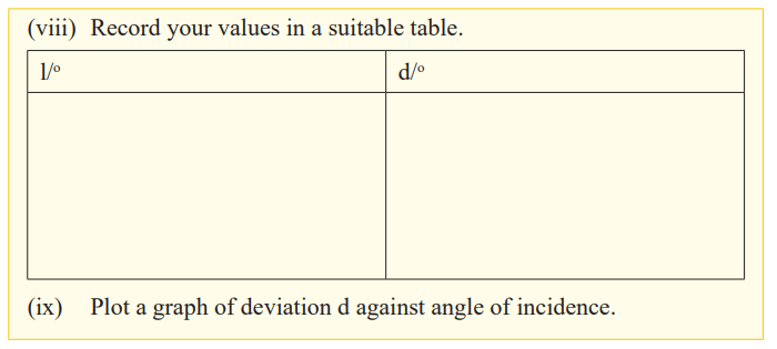
Determination of refractive index of a material of a prism
The graph is a straight line graph and the gradient represents the mean value
which is the refractive index of the material.
Dispersion of light by a prism
A band of seven colours is formed on the screen. The colours are in order of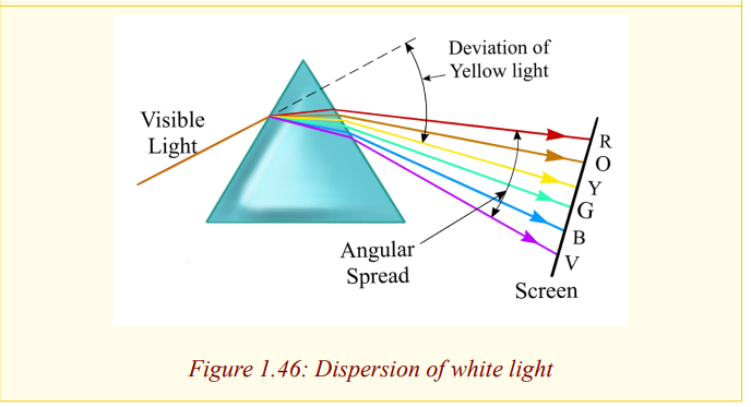
Red, orange, yellow, green, blue, indigo and violet (ROYGBIV) which are
colours of rainbow. This band of colours is called a spectrum. Thus, when
a narrow beam of white light falls on a glass prism, it splits into a range
of colours and these colours separate to form a spectrum, a process called
dispersion. This occurs because white is not a single colour but mixture of all
colours of the rainbow. The prism refracts each colour by a different amount
because the colours travel at different speeds in the glass and thus the glass
has different refractive indices for each colour. The speed of a red colour is
greatest and that of a violet colour is the least, and so the refractive index of a
material of the prism for red colour is the least and that of the violet colour is
the greatest. Now it follows that since the angle of incidence in air is the same
for all the colours, red in deviated least by the prism and the violet rays are the
most deviated as shown in the figure above (exaggerated for clarity because
the colours overlap).
Applications of total internal reflection of light by a prism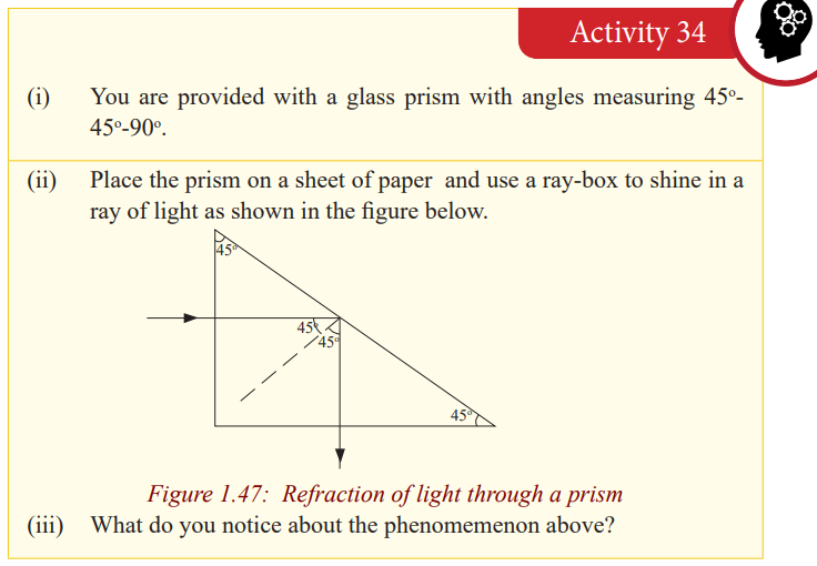
Notice that light goes straight through the first surface and when it meets the
second surface, it is internally reflected. So, the long side of the prism acts as
a mirror and turns light through an angle of 90o
. Two prisms of the same type
as above can be arranged in away and used in a periscope; an instrument used
to see the top of an obstruction.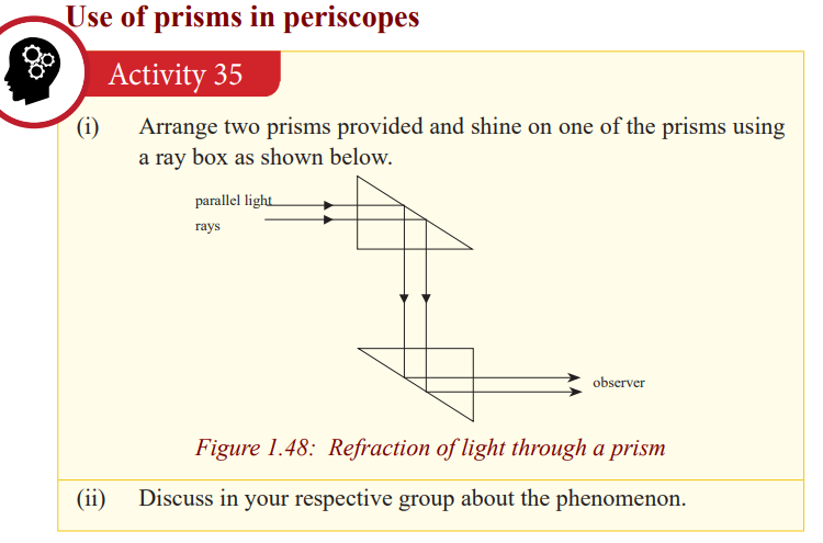
Light is tuned through 90oat each prism and it emerges parallel to the incident
light. In prism periscopes, light from an object is turned through 90o
at each prism ands reaches the observer at a different altitude to that of an object. Sothe image of the object is formed at another altitude but is same size as object.
An arrangement of two prisms each turning light through an angle of 180o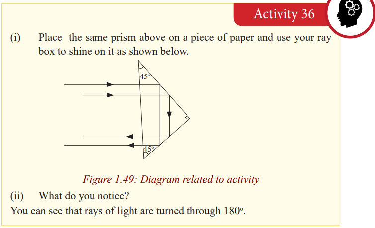
is used in prism binoculars; instruments used to view hidden objects. This willbe discussed in the next unit.
Critical Thinking Exercise
a) Give reasons why prism rather than plane mirrors are used in
periscopes and prism binoculars.b) Explain why diamonds are cut with their sides flat and others slanting.
In periscopes and prism binoculars, plane mirrors can be used but prisms arepreferred because of the following reasons.
In the first place, a prism allows light to undergo total internal reflection and
thus the images are formed by total internal reflection where as a mirror allows
light to both reflect and refract at its surface. So for a prism, all the light
(100%) from the object is reflected but for a mirror some light is absorbed
(about 95% is reflected) and thus a prism produces a brighter image than amirror
The silvering on the mirrors wears off with time but with prism no silveringis needed.
Some mirrors, for example, thick plate mirrors produce multiple images of
one object because of reflections and refractions at the surfaces and inside theglass but a prism produces anyone image.
Diamonds are cut that way so as to make use of total internal reflection. Themultiple reflections inside diamond make it bright.
END UNIT ASSESSMENT
1. An object of height h = 7 cm is placed a distance p = 25 cm in front of athin converging lens of focal length f = 35 cm.
a) What is the height, location, and nature of the image?
b) Suppose that the object is moved to a new location a distance p
= 90 cm in front of the lens. What now is the height, location,
and nature of the image?
2. How far must an object be placed in front of a diverging lens of focal
length 45 cm in order to ensure that the size of the image is fifteen
times less than the size of the object? How far in front of the lens is the
image located?
3. An object is placed (a) 20 cm, (b) 5 cm from a converging lens of focal
length 15 cm. Find the nature, position and magnification of the image
in each case.
4. Find the nature and position of the image of an object placed 10 cm from
a diverging lens of focal length 15 cm.
5. A coin 3 cm in diameter is placed 24 cm from a converging lens whose
focal length is 16 cm. Find the location, size, and nature of the image.
6. An object is placed 30.0 cm in front of a converging lens and then 12.5
cm in front of a diverging lens. Both lenses have a focal length of 10.0
cm. for both cases, find the image distance and describe the image.
7. A 4.00 cm tall light bulb is placed a distance of 45.7 cm from a double
convex lens having a focal length of 15.2 cm. Determine the image
distance and the image size.
8. A 4.00 cm tall light bulb is placed a distance of 8.30 cm from a double
convex lens having a focal length of 15.2 cm. Determine the image
distance and the image size.
9. A 4.00 cm tall light bulb is placed a distance of 35.5 cm from a diverging
lens having a focal length of 12.2 cm. Determine the image distance and
the image size.
10.A beam of parallel rays spreads out after passing through a thin diverging
lens, as if the rays all came from a point 20.0 cm from the center of the
lens. You want to use this lens to form an erect, virtual image that is the
height of the object.
a) Where should the object be placed? Where will the image be?
b) Draw a principal ray diagram.
11.A ray of light incident at an angle i on a prism of angle, A, passes
through it symmetrically. Write an expression for the deviation, d, of
the ray in terms of i and A. Hence find the value of d, if the angle of the
prism is 60o and the refractive index of the glass is 1.48.
12.A beam of monochromatic light in incident normally on the refracting
surface of a 60o glass prism of refractive index 1.62. Calculate the
deviation caused by the prism.
13. a) Define the critical angle of a medium.
b) One side of a triangular glass prism put in a pool of water of
refractive index 4/3 and the other side was left open to air. A ray
of light from water was incident on the prism at an angle i = 21.7o. The
light just grazes as it emerges out of the prism. Given that the
refractive index of glass 1.52, determine the refracting angle A ofthe prism.
14.A monochromatic light is incident at an angle of 45o
on a glass prism of refracting angle 70o
in air. The emergent ray grazes the boundary of
the other refracting surface of the prism. Find the refractive index ofthe material of glass.
15.A prism of diamond has a refracting angle of 60o
. A ray of yellow light is incident at an angle of 60o
on one face. Find the angle of emergenceif the refractive index of diamond for yellow light is 2.42.
16.A ray of light just undergoes total internal reflection at the second face
of a prism of refracting angle 60o
and refractive index 1.5. What is itsangle of incidence on the first face?
17.A sharp image is located 78.0mm behind a 65.0mm-focal-length
converging lens. Find the object distance (a) using a ray diagram, (b)by calculation.
18.What is (a) the position, and (b) the size of the image of a 7.6cm high
flower placed 1.00m from a 50.0mm focal length camera lens?
19.An object is placed 10cm from a lens of 15m of focal length.Determine the image position.
20.Two converging lenses A and B, with focal lengths fA=20cm and fB =
-25cm, are placed 80cm apart, as shown in the figure (1). An object is
placed 60cm in front of the first lens as shown in figure (2). Determine
(a) the position, and (b) the magnification, of the final image formed bythe combination of the two lenses.
21.Where must a small insect be placed if a 25cm focal length diverging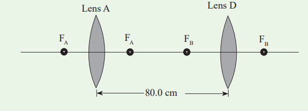
lens is to form a virtual image 20cm in front of the lens?
22.Where must a luminous object be placed so that a converging lens of
focal length 20cm produces an image of size four times bigger than theobject (Consider the case of a real image and the case of a virtual)
23.From a real object AB we want to obtain an inverted image four
times bigger than the object. We place a screen 5m away the object.
Specify the kind, the position and the focus of the lens to use. Give thegraphical and the algebraic.
24.In cinematography the film is located at 30m from the screen and the
image has a magnification of 100. Determine the focal length of thelens used in projection
25.An object AB of 1cm is placed at 8cm from a converging lens of focallength 12cm. Find its image (Position, nature and the size).
26.An object of 2cm is placed at 50cm from a diverging lens of focallength 10cm. Determine its image.
27.An object located 32.0 cm infront of a lens forms an image on a screen
8.00 cm behind the lens. (a) Find the focal length of the lens. (b)Determine the magnification. (c) Is the lens converging or diverging?
28.A movie star catches the reporter shooting pictures of her at home. She
claims the reporter was trespassing. To prove her point, she gives as
evidence the film she seized. Her 1.72m height is 8.25mm high on the
film and the focal length of the camera lens was 210mm. How far awayfrom the subject was the reporter standing?
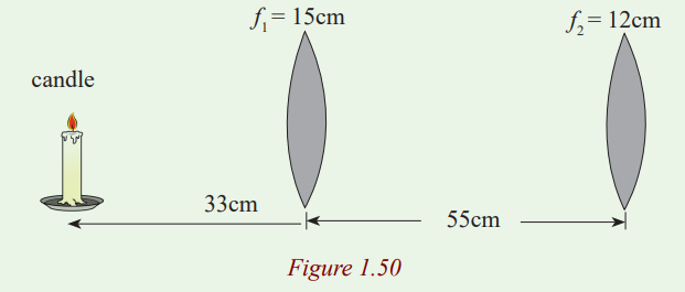
29.A lighted candle is placed 33cm in front of a converging lens of focal
length f1=15cm, which in turn is 55cm in front of another converging
lens of focal length f2=12cm. (a) Draw a ray diagram and estimate
the location and the relative size of the final image. (b) Calculate theposition and relative size of the final image.
30.When an object is placed 60cm from a certain converging lens, it forms
a real image. When the objet is moved to 40cm from the lens, the
image moves 10cm farther from the lens. Find the focal length of thislens.
Unit 2: Optical instruments
Key unit Competence
Describe and use optical instruments.
My goals
By the end of this unit, I will be able to:
* explain an optical instrument.
* explain the physical features of a human eye.
* describe the image formation by the eye.
* identify the physical features of a simple and compound microscope.
* explain the applications of simple and compound microscopes.
* differentiate between simple and compound microscopes.
* explain the operation of a lens camera and its application.
* explain the operation of a slide projector and its applications.
* describe the physical features of a telescope.
* list different types of telescopes.
* demonstrate the operation of telescopes.
* differentiate between telescopes and microscopes.
* identify the physical features of prism binoculars.
INTRODUCTORY ACTIVITY
When a patient goes to hospital having a headache and fever, a doctor may
require a blood test for malaria. When a sample of blood is taken, it is not
possible to check whether a patient has malaria or not. But a laboratory
technician may need to test the blood using some instrument and decidewhether the patient has malaria or not.
Questions:
(i) Which instrument do you think may be used to test malaria from
blood sample?
(ii) In summary, discuss how that instrument function.(iii) What other instrument do you think can be used for such purpose?
Introduction
Once the rules for predicting how rays travel through lenses have been
discussed; a fantastic range of practical devices began to appear which aided
the development of the modern world. The simple magnifying glass became
the basis for telescopes, microscopes and spectacles. These devices were
modified to improve the projection of images and with the discovery and
development of light-sensitive chemicals, gave birth to modern photographyand cinematography.
Definition of an optical instrument
Activity 2.1
In our daily activities and development, we observe different things in
environment or in universe. Sometimes, some objects cannot be easily
observed using our naked eyes. We need to see these very small things at
big distance.
(i) What do you think we use to observe those distant or very small
bodies?
(ii) Discuss the properties used by those instruments?
(iii) Name at least four instruments that people use to observe distant orvery small objects.
We use our eyes to see and view different objects. The eye cannot be used
to view clearly these objects at night, and some distant objects or hidden
objects. Objects which cannot be viewed by the eye can be focused using
other instruments. All the instruments used to aid vision are called Opticalinstruments.
Man has always shown interest in observing things in a more detailed manner.
In your early secondary, you looked at the uses of mirrors. We have also learnt
in unit 1 of this book that lenses are used to focus objects. When the lenses
or mirrors or both are arranged in a way, the arrangement can be used to
observe objects in a more detailed manner. The arrangement makes what we
call a compound optical instrument. The compound instruments include acompound microscope, telescopes, prism binoculars etc.
THE HUMAN EYE
The eye is a biological instrument used to see objects at different distances. It
uses a convex lens system to form a small, inverted, real image of an objectinfront of it.
Structure of the eye
Activity 2
(i) In groups of two, look at one another’s eye.
(ii) Observe critically its external shape.
(iii) Observe it carefully and note its behaviour as one tries to see some
objects in class.Notice that the eye ball is round and fleshy.
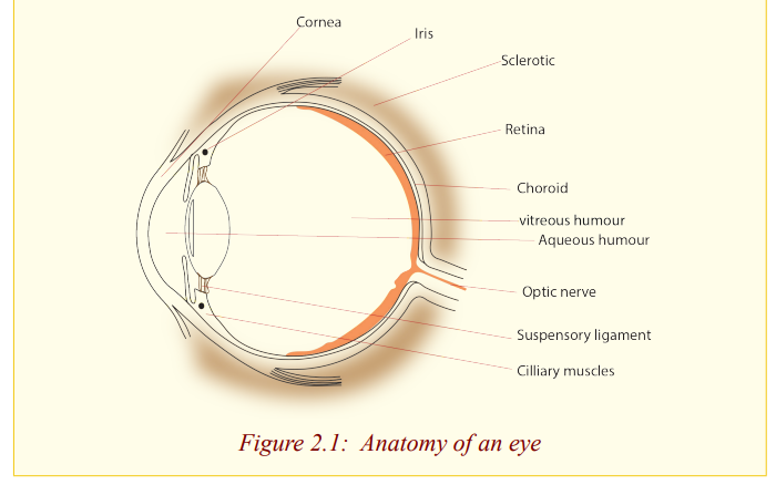
Functions of the parts of the eye
The cornea: It is made out of a fairly dense, jelly like material which provides
protection for the eye, and seals in the aqueous humour. It also
provides most of the power of the eye (59 Dioptres), having about46 Dioptres. So it provides most of the bending of light rays.
The aqueous humour: This is a waterly liquid that helps to keep the cornea ina rounded shape, similar to that of a lens.
The iris: This controls the amount of light entering the eye. The amount of
light that enters the eye is one of the factors determining how
focused an image is on the retina. The brighter the light the eye is
exposed to, the smaller the iris’ opening will be. The brighter the
light the eye is exposed to, the smaller the iris’ opening will be.
The iris is the coloured part of the eye as seen from the outside.
The iris opening or a gap through which light passes is called apupil.
The lens: This is used to focus an image on the retina. It controls the
bending of light rays by change of its shape, a process calledaccommodation, which is done by the ciliary muscles.
The ciliary muscles: These control the thickness of the lens during focusing.
By contracting or squeezing the lens, they make it thicker and
vice versa. Because the power of the lens is directly related to
its thickness, the ciliary muscles change the power of the lens by
their movement.
The retina: This is the light sensitive part of the eye and it is where images
are formed. It contains millions of tiny cells which are sensitive
to light. The cells send signals along the optic nerve to the brain.
So the retina is the screen of the eye and the image is formed by
successive refraction at the surfaces between air, the cornea, the
aqueous humour, the lens and vitreous humour. The retina is
black, which prevents any light rays that hit it from reflections
and thereby changing the image.
The vitreous humour: This is a jerry like substance that helps the eye to
keep its round shape. It is very close in optical density to the lensmaterial.
The yellow spot: This is a small area on the retina where the sharpest image,
that is, the finest detail can be seen.
The optic nerve: This is the nerve that transmits images received by the retina
to the brain for interpretation. The part of the eye where the optic
nerve joins the retina is called the blind spot because no imagescan be observed at at this point.
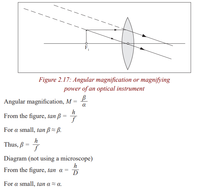
Angular magnification or magnifying power of an opticalinstrument
Accommodation of the eye
Accommodation of the eye is the ability of the eye to see near and distant
objects. The eye is capable of focusing objects at different distances by
automatic adjustment of the thickness of the eye lens which is done by the
ciliary muscles. To focus a distant object, the eye lens is made thinner, so less
powerful, and the rays from the object are brought to focus on the retina by
the eye lens. In this case, the ciliary muscles are relaxed and pull the lens. For
nearer objects, the eye lens must be made thicker and hence more powerful so
that the rays from the near object can be brought to a focus on the retina. Inthis case, the ciliary muscles tighten and squeeze the lens.
Near point and far point of the eye
Activity 5
(i) Hold a book at an arm’s length and move it closer to find the nearest
distance that you can focus the words clearly without straining your
eyes.
(ii) Approximate the distance between your eyes and the book.(iii) What does this distance represent?
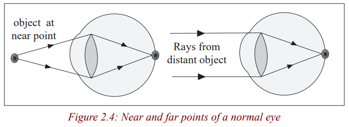
The near point of the eye is the nearest point that can be focused by the un
aided eye. It is a closest distance that the ‘normal’ human eye can observe
clearly; without any strain to the eye. It is called the least distance of distinctvision. The near point of a normal eye is 25 cm.
Activity 6
(i) Look at the trees around your school.
(ii) Now, try to look at objects far from the school.
(iii) Are you able to focus the distant objects?
(iv) Measure this distance from the object to your eye.(v) Write down your observation in the notebook.
Notice that you can not be able to measure this distance. The distance from a
distant object to the eye is the far point of the eye. The far point of the eye isinfinity. The far point is the farthest point that can be focused by the eye.
The distance of 25 cm from the eye is called distance of most distinct vision or
least distance for distinct vision. The range of accommodation of the normal
eye is thus from 25 cm to infinity. This range is based upon the average human
eye which has an age of 40 years. Young persons have a much wider range butthe average 70 year – old has a reduced range.
People with normal vision can focus both near and distant objects.
Defects of vision and their correction
Activity 7
(i) Have you seen before some people putting on eye glasses?(ii) What do you think these glasses(spectacles) are used for.
People put on eye glasses for different reasons. Some people wear them in
order to read a text, some put them on to see near objects if their eyes cannot
be able to do so while others put them on so as to focus distant objects; otherswear them for fan like sun goggles
Short-sightedness (myopia)
Activity 8
(i) Hold a book at an arm’s length and move the lens so that the prints
are read without the eye getting strained.
(ii) Now, try to read the words on a chalkboard a distance from the book.(iii) Are you able to focus both near and distant objects?
People with normal vision can focus clearly near and distant objects. Those
who only focus near objects are said to be short-sighted, meaning that theysee nearer
Short-sightedness is the defect whereby a person can see near objects clearly
but cannot focus distant objects. His far point is nearer than infinity. This is
because the eyeball is too long or the lens is too strong so that rays of lightfrom a distance object are focused in front of the retina.
The rays are focused in front of the retina because the focal length of the eye lens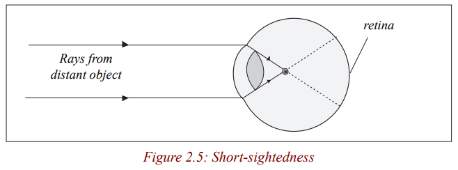
is too short for the length of the eye ball. This defect can be corrected by wearing
a concave (diverging) spectacle lens. The rays of light from a distant object are
diverged so that they appear to come from a point near, and so they are focused bythe eye.
Rays from object at infinity appear to come from a near point F and converge to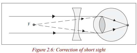
the retina.
Long-sightedness (hypermetropia)
This is where a person is able to see distant objects clearly but cannot focus near
objects. This is because either his eye ball is too short or the eye lens is too weak
(thin) so that rays of light from a close object are focused behind the retina.This eye’s near point is further than 25 cm.
The image of the near object is focused behind the retina because the focal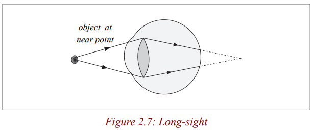
length of the eye lens is too long for the length of the eye ball. This defect can
be corrected by wearing a convex lens spectacle. The rays of light from a near
object are converged so that the rays appear to come from a point far, and soare focused by the eye.
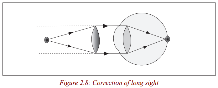
Rays from a near object O appear to come from a distant object.
Presbyopia
Activity 9
(i) How many of you still have their grandparents?
(ii) Have you ever tried to observe how grand parents observe objects?
(iii) Discuss with your neighbour and write in your notebook results ofyour discussion.
When people grow older, their eye lens become stiff and it becomes hard for
the ciliary muscles to adjust it. Such people have a defect called Presbyopia.
Presbyopia is the stiffening of the eye lens such that it is less capable of being
adjusted by the ciliary muscles. This means that the eye lens becomes less
flexible and loses its power (ability) to accommodate for objects at different
distances. This defect is corrected by wearing bifocals spectacles whose lenses
have a top part for looking at distant objects and a bottom part for close ones.
These bifocal spectacles have a diverging top part to correct for distant visionand converging lower part for reading.
Astigmatism
This is the defect that occurs if the curvature of the cornea varies in different
directions so that rays in different planes from an object are focused in
different positions by the eye and the image is distorted. A person suffering
from astigmatism sees one set of lines more sharply than others. This defect is
corrected by wearing corrected lenses. These help to bend the incoming raysto correct for irregular refraction.
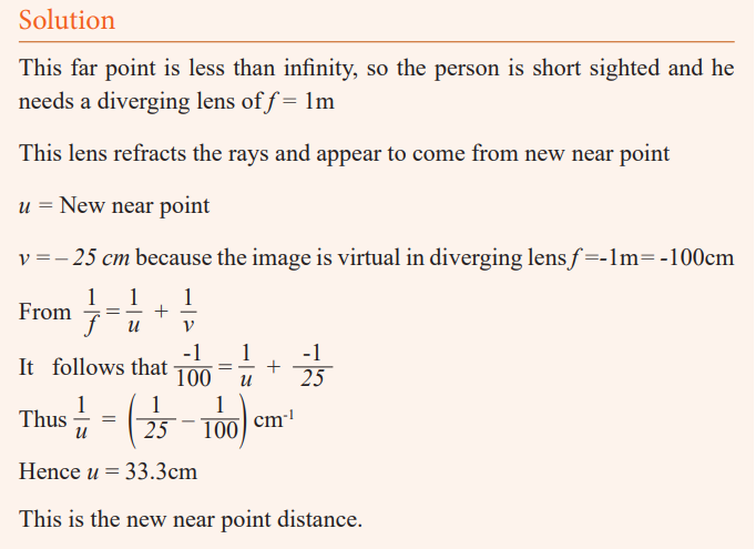
Example
The far point of the defective eye is 1m. What lens is needed to correct
this lens. With this lens, at what distance from the eye is its near point, ifthe near point is 25cm without the lens?
Formation of an image by the eye
Light enters the eye through the transparent cornea, passes through the
lens and is focused on the retina. The retina is sensitive to light and sends
messages to the brain for interpretation. Although the image is inverted, thebrain interpretes it correctly.
Visual Angle
Activity 3
(i) Go outside class and view the trees around.
(ii) Are the trees of the same height?
Notice that some trees at a distance, look shorter than the nearby trees
when it is not the case? Why do you think it is so?Discuss and write down in your notebook about your observation.
The height of an object depends on the angle of elevation of its top from the
eye. The larger the angle, the taller the objects. This angle is called the visualangle.
The visual angle is the angle subtended at the eye by an object.
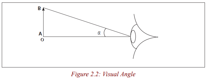
This angle decreases when the distance D increases and increases when the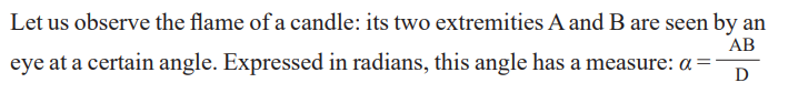
distance D decreases. It also increases when the length AB increases anddecreases when AB decreases. We call it visual angle of the object.
Lead the learners to define the visual angle of an object as the angle between
two rays of light from extremities of the object and penetrating into the eye ofan observer.
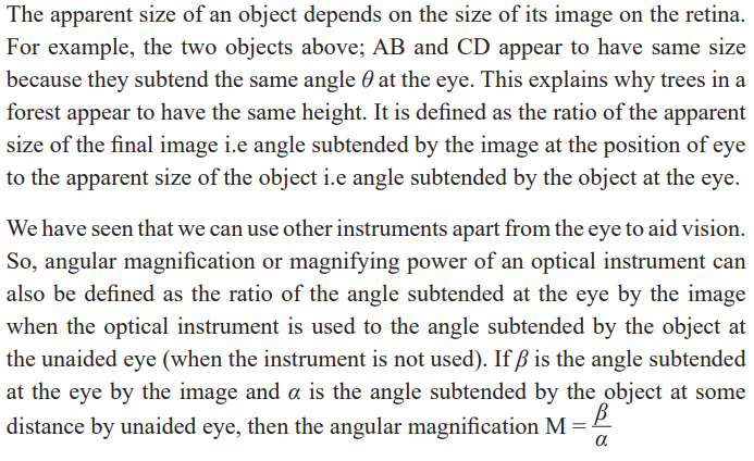
Activity 4
Objects that subtend the same angle at the eye appear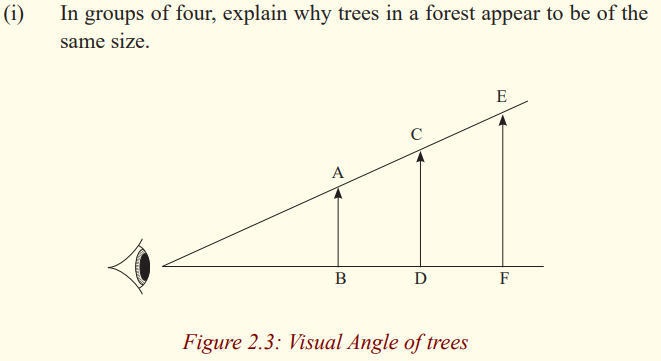
to be of the same size as viewed by the eye.
Application activity 2.1
1. Name the part of the eye
a) which controls how much light enters it,
b) on which the image is formed,
c) which changes the focal length of the crystalline lens.
2. A farsighted person has a near point of 100 cm. Reading glasses
must have what lens power so that this person can read a
newspaper at distance of 25 cm? Assume the lens is very
close to the eye.
3. A nearsighted eye has a near and far point of 12 cm and 17 cm,
respectively.
a) What lens power is needed for this person to see distant objects
clearly, and
b) What then will be the near point?Assume that the lens is 2.0 cm from the eye (typical for eyeglasses).
A lens camera
Activity 10
(i) Make a paper box and carefully use a pin to make a tiny hole in the
centre of the bottom of the paper box.
(ii) Place a piece of wax paper on the open end of the box. Hold the
paper in place with the rubber band.
(iii) Turn off the room lights. Point the end of the box with a hole in a
bright window.
(iv) Look at the image formed on the wax paper.
Which kind of image have you seen? Is it upside down or right side up. Isit smaller or larger than the actual object? What type of image is it?
The image is upside down. The pin hole helps you to see the image of theobject. This device is called a pin hole camera.
Activity 11
(i) When you were going to register for Rwanda National Examinations,
you took some photographs.(ii) What device did the person that took your photograph use?
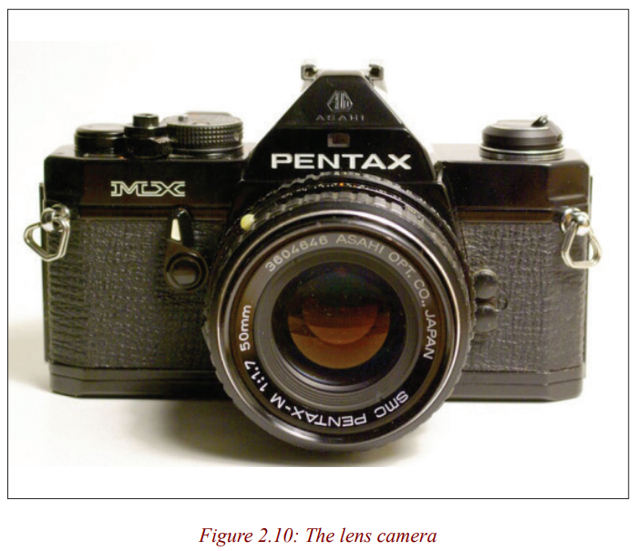
In our daily lives, we take photographs. We use a lens camera to take these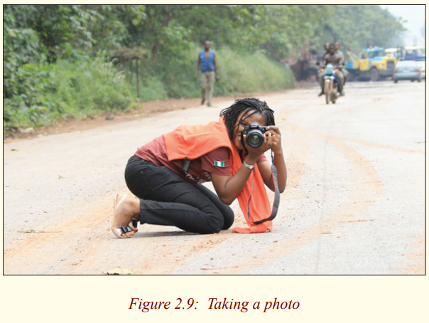
photographs.
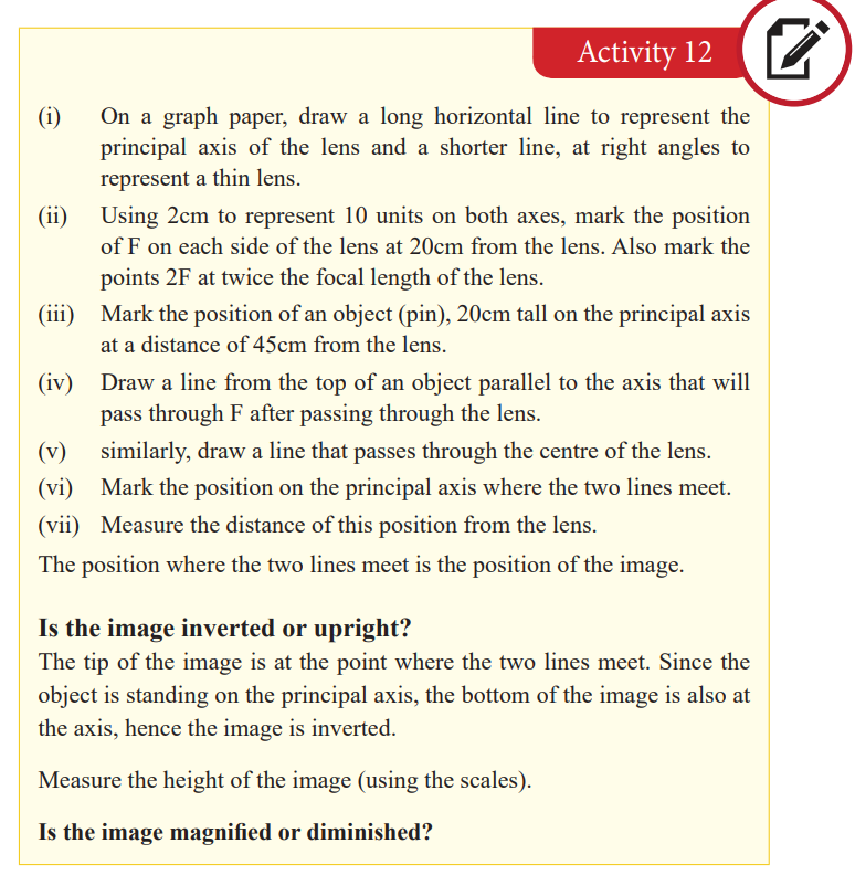
Activity 12
(i) Enlarge the hole in the pinhole camera above at the front of the box
and hold convex lens over the hole.
(ii) Adjust the position of the lens for either near or far objects to make
a sharp image on the screen.
(iii) Is the image erect or inverted? If the objects are coloured, is theimage coloured?
Notice that the image formed is inverted and coloured if the object is coloured.
By placing a lens above the hole, you are making a lens camera from a pinhole camera.
Formation of images by a lens camera
Activity 13
(i) Draw a ray diagram for the formation of an image of an object
placed at a point beyond 2F of a thin converging lens.
(ii) State the nature and size of the image.Is the image bigger or smaller?
We have already seen that when an object is beyond 2F of a thin converginglens, the image formed is smaller than the object.
A camera consists of a light- tight box with a convex (converging) lens at
one end and the film at the other end. It uses the convex lens to form a small,inverted, real image on the film at the back.
The lens focuses light from the object onto a light sensitive film. It is moved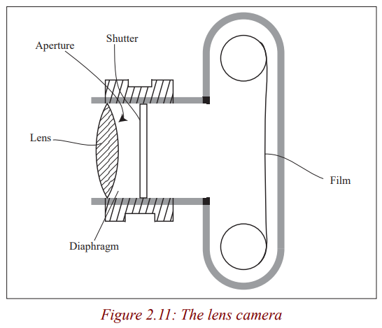
to and fro so that a sharp image is formed on the film. In many
cameras, this happens automatically. In cheaper cameras, the lens
is fixed and the photographer moves forwards and backwards tofocus the object.
The diaphragm is a set of sliding plates between the lens and the film. It
controls the aperture (diameter) of a hole through which light
passes.
In bright light, a small aperture is used to cut down the amount
of light reaching the film and in dim light, a large hole is needed.
Very large apertures give blurred images because of aberrations
so the aperture has to be reduced to obtain clear images.
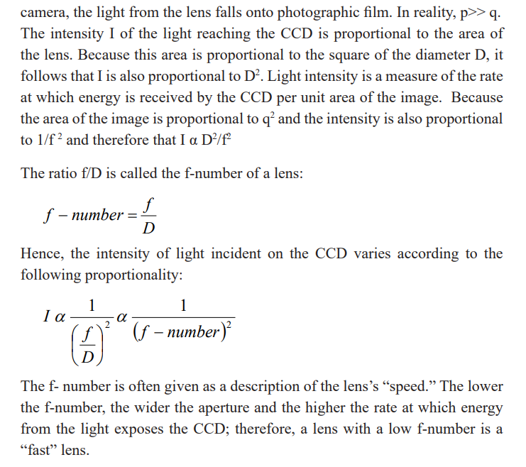
In many cameras, the amount of light passing through the lens
can be altered by an aperture control or stop of variable width.
This size of the hole is marked in f – numbers i.e 1.4, 2, 2.8, 4,
5.6, 8, 11, 16, 22, 32. The smaller the f-number, the larger the
aperture. An f-number of 4 means the diameter d of the aperture
is ¼ the focal length, f of the lens. To widen the aperture, the f
number should therefore be decreased.
The aperture also controls the depth of field of the lens camera.
The depth of field is a range of distances in which the camera can
focus objects simultaneously. This depth of field is increased byreducing the aperture.
This large depth of field ensures a large depth of focus. The
depth of focus is the tiny distance the film plane can be moved
to or from the lens without defocusing the image. A large depth
of focus means that both near and far objects appear to be in
focus at the same time which is obtained by a small hole in thediaphragm.
The shutter controls the exposure time of the film. It opens and closes quicklyto let a small amount of light into the camera.
The exposure time affects the sharpness of the image. When the exposure
time is short, the image is clear (sharp) but when it is long theimage becomes blurred.
The film. This is where the image is formed. It is kept in darkness until the
shutter is opened. It is coated with light sensitive chemicals
which are changed by the different shades and colours in the
image. When the film is processed, these changes are fixed andthe developed film is used to print the photograph.
Note that a diminished image is always formed on the film and that the image
of distant object is formed on a film at distance f from the lens. For near
objects, the lens is moved further away from the film (closer to the object) to
obtain a clear image. In this case, the film is at a distance greater than f of the
lens. Digital cameras are similar to film cameras except that the light does not
form an image on photographic film. The image in a digital camera is formedon a charge-coupled device (CCD).
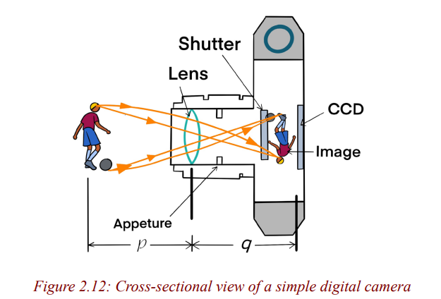
The CCD is the light-sensitive component of the camera. In a nondigital
Application activity 2.2
1. A camera gives a clear image of a distant landscape when the lens
is 8 cm from the film. What adjustment is required to get a
good photograph of a map placed 72 cm from the lens?
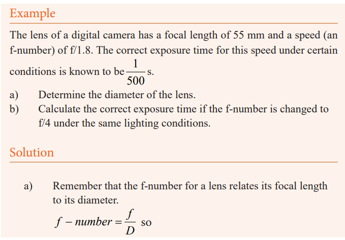
2. The lens of a certain 35 mm camera (where 35 mm is the width of
the film strip) has a focal length of 55 mm and a speed (an
f-number) of f/1.8. The correct exposure time for this speed
under certain conditions is known to be (1/500) s.
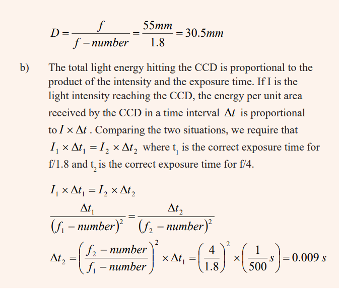
a) Determine the diameter of the lens.
b) Calculate the correct exposure time if the f-number ischanged to f/4 under the same lighting conditions.
The slide projector
Activity 14
(i) Have you ever seen an instrument called a slide projector?
(ii) What is that instrument used for?
(iii) Have you ever watched a cinema where the pictures are seen on the
white wall?
(iv) What device were they using to throw the pictures on the screen
(wall or white cloth)?
(v) Where do you think the pictures came from?(vi) Are the images small or large?
The pictures are thrown on the screen using a slide projector.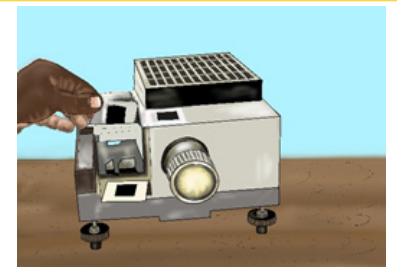
A projector is a device used to throw on a screen a magnified image of a filmor a transparent slide. It produces a magnified real image of an object.
A slide projector is an opto-mechanical device for showing photograhic slides.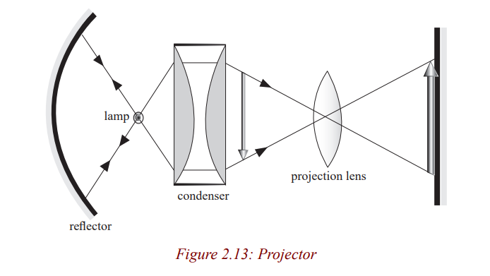
It consists of an illumination system and a projection lens. The illumination
system consists of a lamp, concave reflector and the condenser. The illuminant
is either a carbon electric arc or a quartz lamp to give a small but very highintensity source of light in order to make the image brighter.
The lamp is situated at the centre of curvature of the mirror so that the rays are
reflected back along their original path. The concave mirror reflects back light
which would otherwise be wasted at the back of the projector housing. The
condenser consisting of two Plano concave lenses collects light which would
otherwise spread out and be wasted, and concentrates it on to the film (slide)so that it is very bright and evenly illuminated.
The light is then scattered by the film and focused by a convex projection lens
on to the film. The projection lens is mounted in the sliding tube so that it ismoved to and fro to focus a sharp image on the screen.
Application activity 2.3
1. A colour slide has a picture area 2.4 cm x 3.6 cm. Find the focal
length of the projection lens which will be needed to throw an image1.2m x 1.8m on a screen 5m from the lens.
2. A projector projects an image of area 1 m2
onto a screen placed 5m
from the lens. If the area of the slide is 4 cm2
, calculate;
(i) The focal length of the projection lens.(ii) The distance of the slide from the lens
Activity 15
Make a projector on the bench using a ray box lamp, a single convex lens (focal
length about 5 cm) for the condenser; a slide; a convex lens (focal length 5cm or
10cm) as the projection lens and a sheet of paper for the screen.
Is the image inverted?By how much is it magnified?
Note that if the film is placed just after the lamp, the object would be poorly
illuminated. So to give a bright picture, a condenser is included. The film O
is placed between F and 2F of the projection lens so that the image I is real,
inverted and magnified. The film is put in the projector while it is upside downso that the picture on the screen is upright.
Microscope
Simple Microscope (Magnifying Glass)
Activity 16
(i) Hold a hand lens at above the word Rwanda at a distance of about
4cm from the word.
(ii) Move the lens farther away slowly from the word while observing
the word through the lens.
(iii) What changes do you notice after observing?
(iv) Share ideas with your neighbour and write your observation inyour notebook.
The word Rwanda becomes larger and larger and finally disappears. This word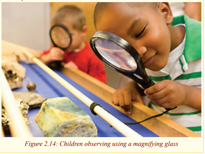
gets larger because of the lens. We say that it is being magnified by the lens.
Activity 17
(i) Place your hand on a table and hold a hand lens above it and do the
same as in activity 16.(ii) What do you notice?
Notice that the hair (fur) and other small holes on the skin are seen clearly.
These parts of the skin are made bigger by the glass lens and this enables one
to see them clearly. This lens which magnifies images is called a magnifyingglass or a simple microscope.
A magnifying glass consists of a thin converging lens and It is used to view
very small organisms or parts of organisms which cannot be easily seen by thenaked eye.
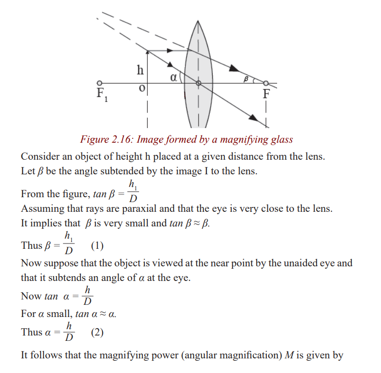
Formation of images by a magnifying glass
Activity 18
Using the knowledge from thin lenses, draw a ray diagram to show the
formation of an image by a magnifying glass.State the characteristics of the image formed.
We have already seen in unit 1 that when an object is between the lens and its
principal focus, the image formed is magnified and upright. So, a magnifying
glass forms a virtual, upright, magnified image of an object placed betweenthe lens and its principal focus.
Activity 19
Making a simple microscope
(i) Use a pin or a nail to make a hole about 2 mm in diameter in a piece
of a kitchen foil or glass.
(ii) Carefully let a drop of water fall on the hole so that it stays there
and acts as a tiny lens with short focal length.(iii) Use it to observe prints on a piece of paper.
Simple microscope (magnifying glass) in normal adjustment.
The magnification of a magnifying glass depends upon where it is placed
between the user’s eye and the object being viewed and the total distancebetween them.
Activity 20
(i) Carefully place a magnifying glass above some prints on a piece of
paper and adjust it until they are seen clearly.
(ii) Make sure that you don’t feel any strain in the eye while you are
observing.(iii) What do you think is the position of the image from the eye?
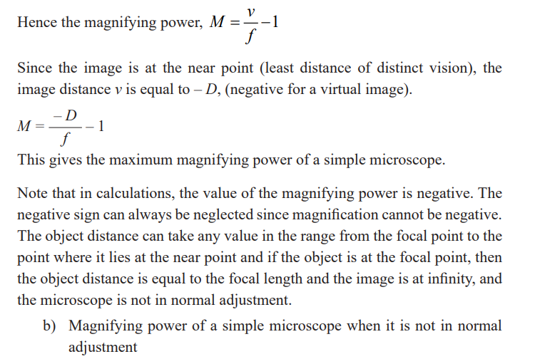
The image is at the least distance of vision since the eyes are not strained andthe magnifying glass is said to be in normal adjustment.
A microscope is in normal adjustment if the final image is formed at the nearpoint, and it is not in normal adjustment if the final image is at infinity.
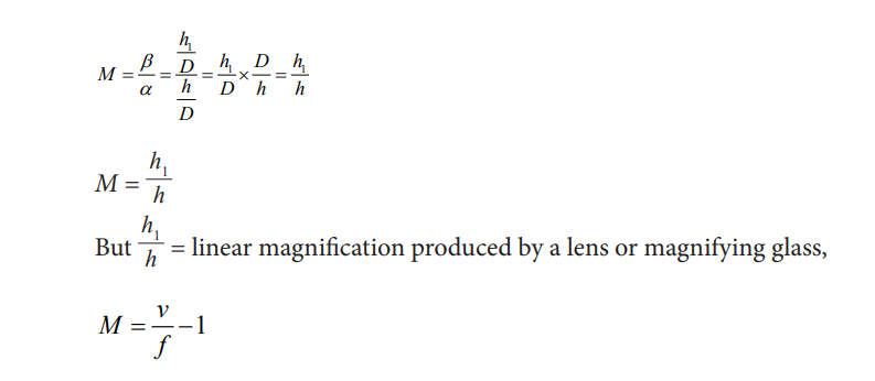
Magnifying power of a simple microscope
We have already seen that the size of the image depends on the angle subtended
by the object on the eye called the visual angle. Thus, the magnifying powerdepends on the visual angle.
It is defined as the ratio of the angle subtended by the image to the lens to the
angle subtended by the object at the near point to the eye.a) Magnifying power of a simple microscope in normal adjustment
Application activity 2.4
1. Find the angular magnification produced by a simple microscope of
focal length 5cm when used not in normal adjustment.
2. Explain why angular magnification of a simple microscope is high
for a lens of short local length.
3. Why the image formed by magnifying glass is free from chromaticabberation.
Activity 21
In groups of five, discuss why the image formed in a magnifying glass is
almost free of chromatic abbreviation.
When an object is viewed through the magnifying glass, various coloured
images corresponding to IR, IV for red and violet rays are formed but each
image subtends the same angle at the eye close to the lens and therefore these
colours overlap. The overlap of these colours makes a virtual image seen in amagnifying glass free of a chromatic abberation.
Group Activity 22
Provided a magnifying glass, go outside and pick different kinds of leaves.
Examine, with the use of a magnifying glass, the structures of the leaves.Discuss in details the structural characteristics of each leaf
Group Activity 23
You are provided with dirty water in a glass container.
Use the magnifying glass provided and view some living organisms in it.Record what you see.
Activity 24
(i) Observe critically and describe the activity being done in the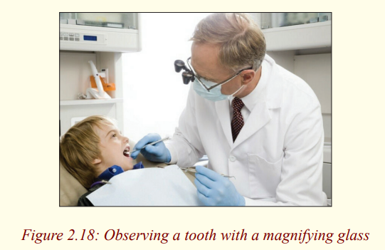
photograph.(ii) State other uses of a magnifying glass.
Uses of magnifying glass: Magnifying glasses have many different uses.
Some people use it for fun activities such as starting fires, or use the lens to
help them read. You can start a fire with a magnifying glass when the sun rays
are concentrated on the lens. Some retail stores sell reading glasses with the
double convex lens. In everyday life, magnifying glasses can be used to do a
variety of things. The most common use for magnifying glasses would be howscientists use them, they use magnifying glasses to study tiny germs
The compound microscope
Activity 25
Have you ever heard or seen an instrument called a compound
microscope?What is it used for?
The compound microscope is used to detect small objects; is probably the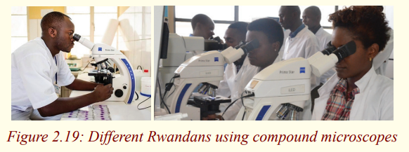
most well-known and well-used research tool in biology.
Activity 26
Observe the above pictures carefully and discuss places where a compound
microscope is used in daily life.In daily life, microscopes are used in hospitals, in biology laboratories, etc.
Activity 27
(i) You are provided with two lenses of focal lengths 5cm and 10cmtogether with a half meter ruler and some plasticine.
(iii) Move the object to and fro until it appears in focus.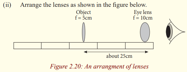
What do you notice about the image? Is it distorted? Is it coloureddifferently in any way?`
By arranging the lenses as above, you have actually made a compound
microscope. We have already seen how a single lens (magnifying glass) can
be used to magnify objects. However, to give a higher magnifying power, twolenses are needed. This arrangement of lenses makes a compound microscope.
It produces a magnified inverted image of an object.
A compound microscope is used to view very small organisms that cannot beseen using our naked eyes for example micro organisms.
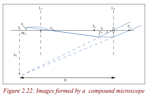
A compound microscope consists of two convex lenses of short focal lengths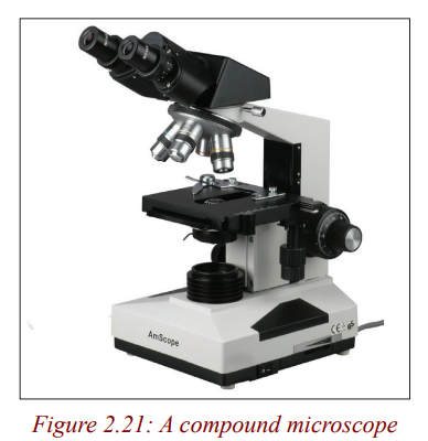
referred to as the objective and the eye piece. The objective is nearest to the
object and the eye piece is nearest to the eye of the observer. The object to be
viewed is placed just outside the focal point (at a distance just greater than the
focal length) of the objective lens. This objective lens forms a real, magnified,
inverted image at a point inside the principal focus of the eye piece. This
image acts as an object for the eye piece and it produces a magnified virtual
image. So the viewer, looking through the eye piece sees a magnified virtualimage of a picture formed by the objective i.e of the real image.
Image formation in a compound microscope
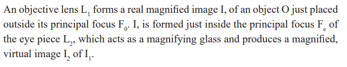
Compound microscope in normal adjustment (normal use)
Activity 28
You are provided with a bird's feather; observe it critically using a
compound microscope and draw it in a fine detail.Make sure you observe the features when your eyes are relaxed.
When the eyes are relaxed, the image is at the near point and the compound
microscope is said to be in normal adjustment. The compound microscope is
in normal adjustment when the final image is formed at the near point (leastdistance of distinct vision), D of the eye.
Angular magnification (magnifying power) of a compound
microscope
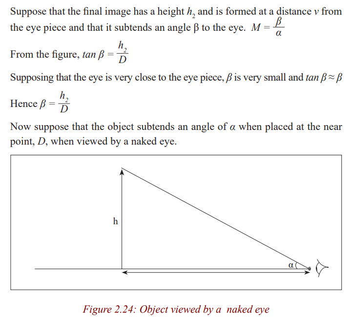
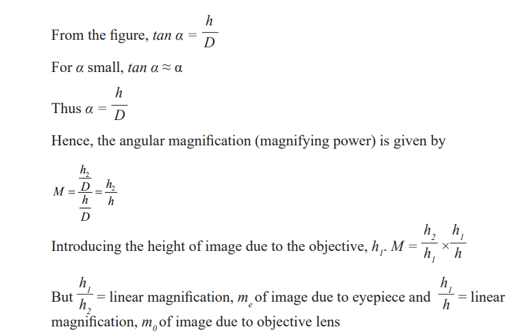
The magnifying power of a compound microscope is the ratio of the angle
subtended by the final image to the eye when the microscope is used to theangle subtended by the object the unaided eye.
Angular magnification of a compound microscope in normal use
We have already seen that when a microscope is in normal use, the image I2is formed at the least distance of distinct vision, D from the eye. Thus v = D.
Consider an object of height h at a given distance slightly greater than the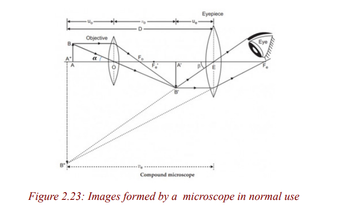
focal length of the objective lens.
Example
A compound microscope has an eye piece of focal length 2.50cm and an
objective of focal length 1.60cm. If the distance between the objective
and eye piece is 22.1cm, calculate the magnifying power produced whenthe final image is at infinity.
Activity 29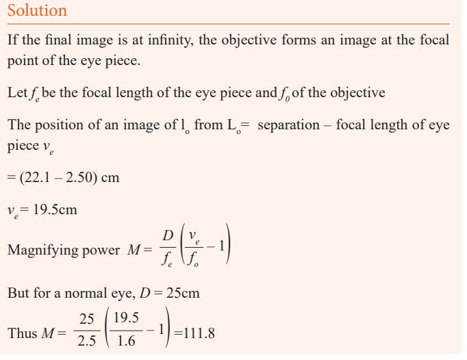
Viewing specimens
The purpose of this exercise is to view micro organisms found in pond
water while learning to operate a microscope.
Equipment
* Microscope
* Jar of pond water
* Slide
* Coverslip* Dropper
Procedure
1. Collect a jar of pond water containing micro organisms. To ensure
that you capture the largest number of micro organisms, do not
simply scoop a jar of water from the centre of a pond. Instead, fill the
jar partway with pond water and then squeeze water into the containerfrom water plants or pond scum.
3. Set up the microscope.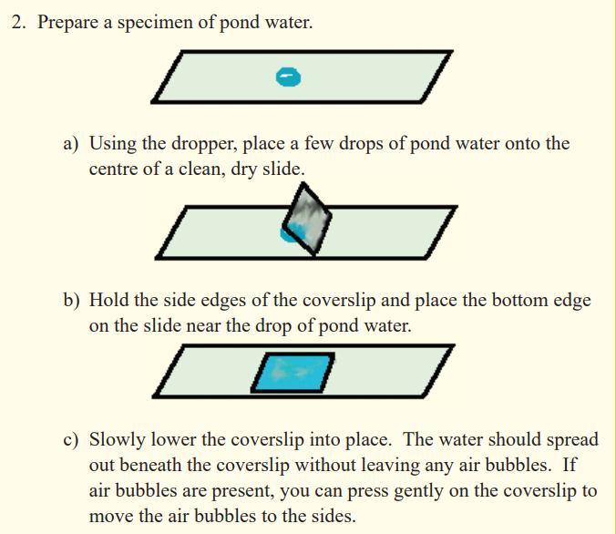
a) Remove the dust cover from the microscope.
b) Plug in the microscope.c) Turn on the microscope’s light source.
4. View the specimen with the low-power objective. Move the slide
around on the stage using your fingers or the control knobs until youfind a micro organism.
5. View the micro organism with the high-power objective.
6. Sketch a picture of the micro organism.
7. Repeat steps 4, 5, and 6 until you have sketched atleast five differentmicro organisms.
8. Turn off the microscope.
a) Carefully, lower the objective to its lowest position by turning
the coarse’ adjustment knob.
b) Turn off the light source.
c) Remove your slide. Clean the slide and cover slip with water.
d) Unplug the microscope and store it under a dust cloth.
Application activity 2.5
A compound microscope consists of a 10× eyepiece and 50× objective
17.0 cm apart. Determine (a) the overall magnification, (b) the focal length
of each lens, (c) the position of the object when the final image is in focuswith the eye relaxed. Assume a normal eye, so N = 25 cm.
Telescopes
Activity 30
You have heard in your early secondary that there are some heavenly and
distant earthly bodies that cannot be seen by our naked eyes. How did thepeople know that there exist such bodies?
Which instrument do you think is used to see these bodies and to observewhat takes place on these bodies?
Why do you think it is difficult to see distant objects using our eyes?
Telescopes are instruments used to view distant objects such as stars and other
heavenly bodies. Distant objects are difficult to see because light from them
has spread out by the time it reaches the eyes, and since our eyes are too smallto gather much light.
There are two kinds of telescopes; refracting telescopes and reflectingtelescopes.
Refracting telescopes
Activity 31
(i) Hold a convex lens of focal length 5cm close to your eye.
(ii) Hold another lens of focal length 20cm at an arm’s length.
(iii) Use the lens combination to view distant objects.
(iv) Adjust the distance of the farther lens until the image is clear (take
care not to drop the lenses).What type of image do you see?
The above lens combination is a refracting telescope. It is called a refracting
telescope because it forms an image of the object by refracting light. Therefore,
Refracting telescopes use lenses and they form images by refraction of light.Below are different kinds of refracting telescopes.
Astronomical telescope
The telescope made in the above activity is called an astronomical telescope.
It consists of two convex lenses, the objective lens of long focal length and aneye piece lens of short focal length.
An astronomical telescope in normal adjustment
Activity 32
Using a telescope made in activity (30) above, view a distant object by
moving the lenses so that the eyes are relaxed.What do you think is the position of the image?
When the eyes are relaxed, the image is at infinity and the telescope is in
normal adjustment. Therefore, an astronomical telescope is in normaladjustment when the final image is formed at infinity.
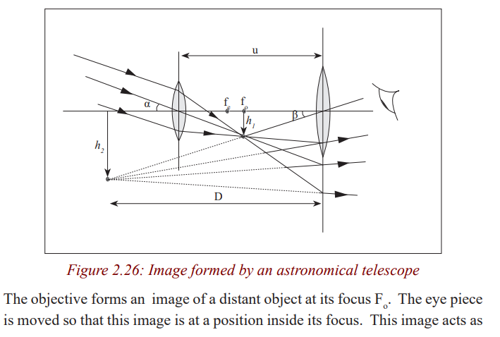
The rays of light coming from a distant object form a parallel beam of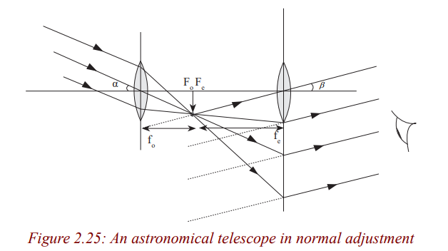
light. This parallel beam is focused by the objective lens and it forms a real,
diminished image at its principal focus Fo
. The eye piece is adjusted so that
this image lies in its focal plane. This image acts as the object for the eyepiece and the eye piece produces the image at infinity.
Note that in normal adjustment, the eye is relaxed or un accommodated whenviewing the image. In this case, the eye has minimum strain.
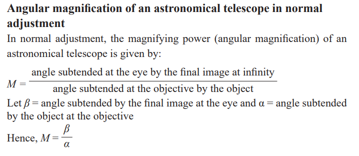
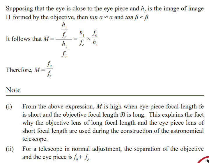
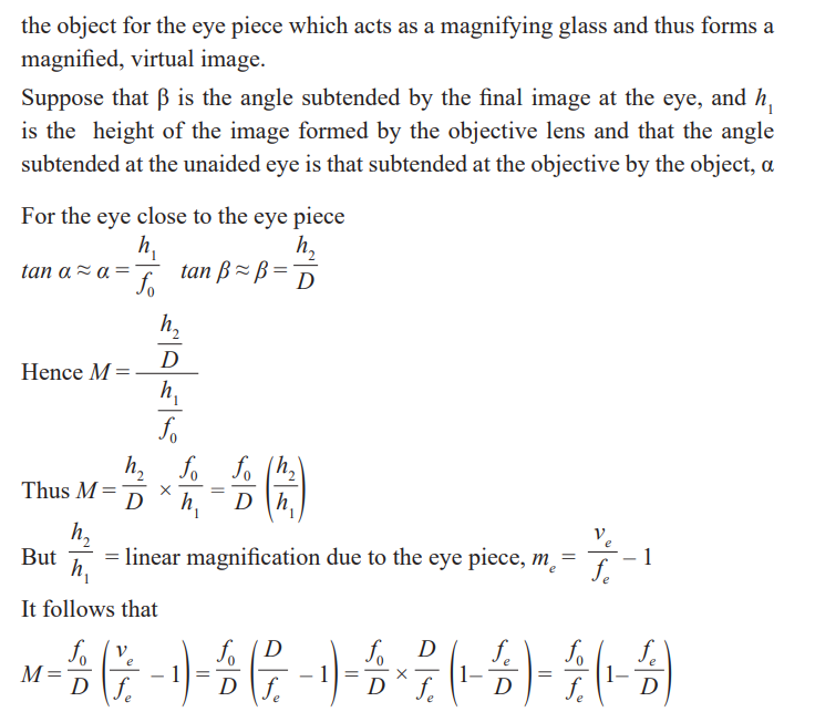
Magnifying power or angular magnification of an astronomicaltelescope
The magnifying power of a telescope is the ratio of the angle subtended by
the image to the eye when the telescope is used to the angle subtended at the
unaided eye by the object. Since the telescope length is very small compared
with the distance of the object from either lens, the angle subtended at the
unaided eye by the object is the same as that subtended at the objective by theobject.
Activity 33
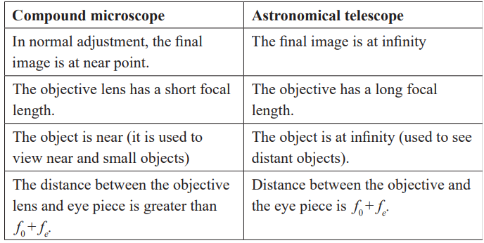
Discuss and give a summary of differences between a compoundmicroscope and an astronomical telescope.
The table below shows the differences between a compound microscope andan astronomical telescope.
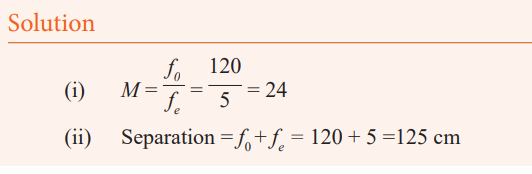
Example
An astronomical telescope has an objective lens of focal length 120
cm and an eye piece of focal length 5 cm. If the telescope is in normaladjustment, what is;
(i) The angular magnification (magnifying power)(ii) The separation of the two lenses?
Application activity 2.6
An astronomical telescope is used to view a scale that is 300 cm from the
objective lens. The objective lens has a focal length of 20cm and the eye
piece has a focal length of 2 cm. Calculate the angular magnification whenthe telescope is adjusted for minimum eye strain.
An astronomical telecope with the final image at the near point
In this case, the image is seen in detail but the telecope is not in normaladjustment (use) because the eyes are strained.
The eye ring
The eye ring is the best position to place the eye in order to be able to view
as much of the final image as possible. The best position for an observer to
place the eye when using a microscope is where it gathers most light from that
passing through the objective. In this case, the image is brightest and the field
of view is greatest. In case of the telescope, all the light from a distant object
must pass through the eye ring after leaving the telescope. So by placing
the eye at the eye ring, the viewer is able to see the final image as much aspossible.
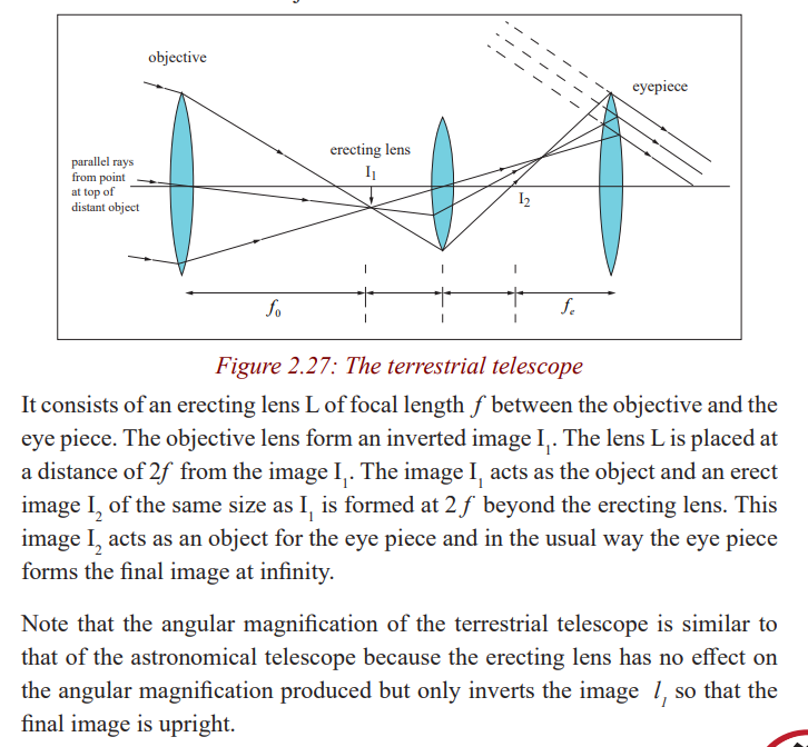
Terrestrial telescope
An astronomical telescope produces an inverted image, so it is not suitable
for viewing objects on the earth. It is suitable for viewing stars and other
heavenly bodies. A terrestrial telescope provides an erect image and thismakes it suitable to view objectives on the earth.
Activity 34
Discuss the advantages and disadvantages of a terrestrial telescope overan astronomical telescope.
Galilean Telescope
Activity 35
(i) Hold a concave lens of focal length 5cm close to your eye.
(ii) Hold another convex lens of focal length 20cm at an arm’s length.
(iii) Use the lens combination to view distant objects.(iv) What is the nature of the image?
The above lens combination is a Galilean telescope. A Galilean telescope
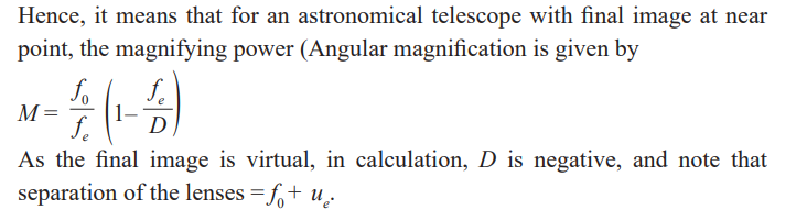
consists of an objective lens which is a convex lens of long focal length and an
eye piece which is a concave lens of short focal length. It forms erect imagesboth in normal and not in normal adjustment.
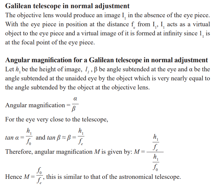
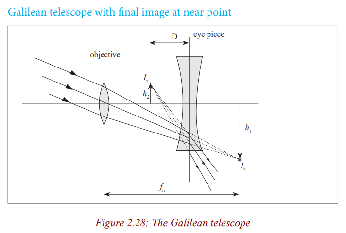
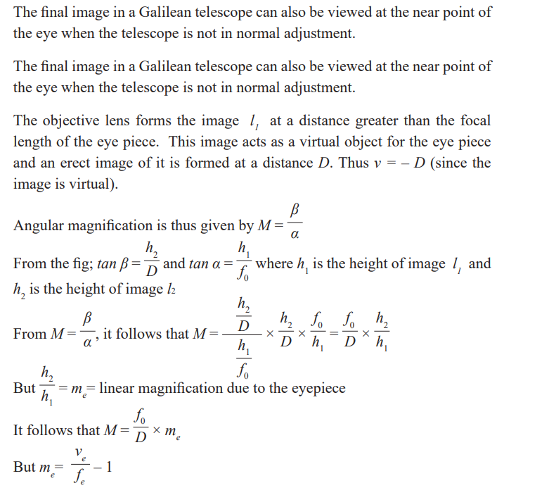
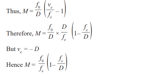
Activity 36
Discuss the advantages and disadvantages of a Galilean telescope over anastronomical telescope and write them in your notebook.
Reflecting telescopes
Activity 37
Take the case of a TV satellite dish in the neighborhood. Discuss andexplain the functioning and principle of a satellite dish
Reflecting telescopes consist of a large concave mirror of long focal length as
their objective. There are three kinds of reflector telescopes, all named aftertheir inventors.
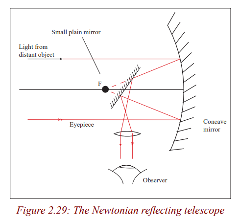
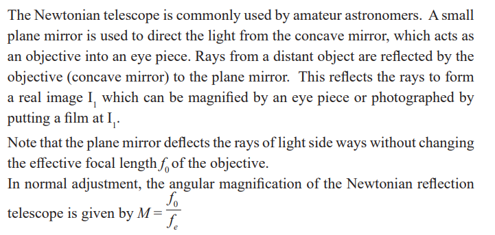
Cassegrain reflecting telescope
This is the type used in most observatories It consists of a concave mirror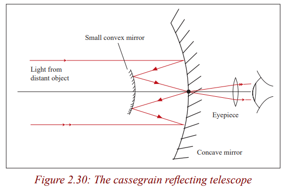
which acts as an objective, a small convex mirror and the eye piece lens. Light
from a distant object is reflected by the concave mirror to the convex mirror
which reflects it back to the centre of the concave mirror where there is a small
hole to allow the light through. So the convex mirror forms the final image(real) at the pole of the objective.
Coude Reflector Telescope
This is a combination of Newtonian and cassegrain reflector telescopes.
The plane and convex mirrors used in reflecting telescopes are used to bring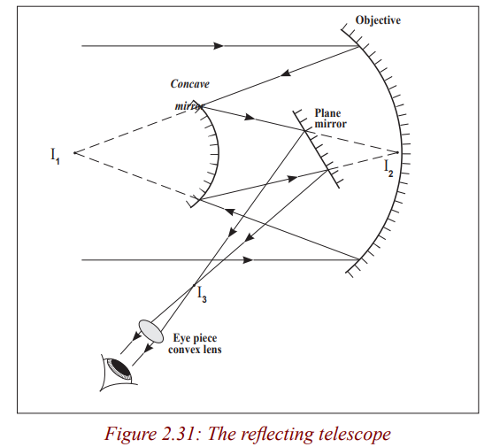
the light to a more convenient focus where the image can be photographed andmagnified several times by the eye piece for observation.
Activity 38
Discuss and explain the advantages of reflecting telescopes over refractingtelescopes.
The reflecting telescopes are free from chromatic aberration since no refraction
occurs. The image formed is brighter than in refracting telescopes where thereis some loss of light during refraction at the lens surfaces.
Spherical aberration can be eliminated by using a parabolic mirror instead of a
spherical mirror as an objective. They have a power because of higher ability
to distinguish two closely related objects because of the large diameter of
the parabolic mirror. We say that they have a high resolving power. They areeasier to construct since only one surface requires to be grounded.
Critical Thinking Exercise
What is meant by the resolving power of an optical instrument? Explain its
usefulness.
Explain why astronomers use reflecting telescopes rather than refractingtelescopes?
Prism binoculars
Activity 39
Have you ever asked yourself how tourists and scientists are able to see
distant animals and birds in a forest or any hidden places?Discuss with your neighbour and write in your notebook the observation.
Tourists and scientists use prism binoculars to view wild animals and birds inhidden places such as caves and forests.
These consist of a pair of refracting astronomical telescopes with two totally
reflecting prisms between each objective and eyepiece. The prisms use total
internal reflection to invert rays of light so that the final image is seen the
correct way. These prisms reflect up and down the light and by doing so, theyshorten the length of the instrument.
Prism A causes lateral inversion and prism B inverts vertically so that the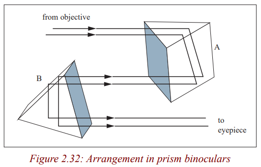
final image is the same way round and same way up as the object. Each prism
reflects light through 180o
. This makes the effective length of each telescope
three times shorter than the distance between the objective and the eye piece.So good magnifying power is obtained with compactness.
END UNIT ASSESSMENT
1. A certain nearsighted person cannot see distinctly objects beyond 80
cm from the eye. What is the power in diopters of the spectacle lensesthat that will enable him to see distant objects clearly?
2. Explain the difference between the terms magnifying power and
magnification, as used about optical systems. Illustrate this, by
calculating both, in the case of an object placed 5.0 cm from a simple
magnifying glass of focal length 6.0 cm, assuming that the minimumdistance of distinct vision for the observer is 25 cm.
3. An eyepiece is made of two positive thin lenses, each of focal length f
= 20 mm, separated by a distance of 16 mm.
(a) Where must a small object viewed by the eyepiece be placed so
that the eye receives parallel light from the eyepiece?
(b)Does the eye see an erect image relative to the object? Is it
magnified?(c) Use a ray-trace diagram to answer these questions by inspection.
4. A common telephoto lens for a 35 mm camera has a focal length of
200 mm; its range from to (a)What is the corresponding range of
aperture diameters? (b)What is the corresponding range of imageintensities on the film?
5. What is the maximum stop rating of a camera lens having a focal
length of and a diameter of ? If the correct exposure at , whatexposure is needed when the diaphragm setting is changed to ?
Unit 3 : Moments and Equilibrium of Bodies
Key Unit Competence
Analyse the principle of moments and equilibrium of bodies. .My goals
By the end of this unit, I should be able to:
* Explain the principle of moments and apply it to equilibrium of a
body.
* Come out with the effects of forces when applied onto a body.* Know the effects of forces.
INTRODUCTORY ACTIVITY
When a patient goes to hospital having a headache and fever, a doctor may
require a blood test for malaria. When a sample of blood is taken, it is not
possible to check whether a patient has malaria or not. But a laboratory
technician may need to test the blood using some instrument and decidewhether the patient has malaria or not.
Questions:
(i) Which instrument do you think may be used to test malaria from
blood sample?
(ii) In summary, discuss how that instrument function.(iii) What other instrument do you think can be used for such purpose?
Introduction
In here, we shall majorly concetrate on the turning effect of force. As you
know, it is very hard to close a door when you apply force near its turning
point. That’s why door handles are always put at the end of the door so that
the distance from the turning point to where force is applied increases. This
increases the turning effect of the force applied. Which is the effect of forceson bodies one of our interest in this unit.
Scalar and vector quantities
Activity 1
Try to stand bricks in a line behind one another. Push one brick.
(i) What happens to other bricks?(ii) What if in the process one brick stops, what would happen?
In daily life, we normally pull the objects from one place to another. When
pulling a goat that is to be tethered, obviously it will take the direction of the
pull. We can call this a force. This is a quantity that changes body’s state ofrest or uniform motion.
You noticed that after pushing your friend he/she changed position and
direction. Hence, a force has both magnitude and direction. This quantity can
be termed as a vector quantity. This is a quantity with both magnitude anddirection.
Activity 2
(i) Using the above example, discuss in groups or as a class other
vector Quantities.
(ii) Analyse the effects of these physical quantities.
(iii) In daily life, how are these quantities utilised?(iv) Ask your friend what time is it?
You will realise that he/she will tell the exact time not even indicating direction.Such a quantity is termed to be a scalar quantity.
A scalar quantity is a physical quantity that is defined by only magnitude(size).
Other examples of scalar quantities are volume, mass, speed, and time
intervals. The rules of ordinary arithmetic are used to manipulate scalarquantities.
Application activity 3.1
Of the following physical quantities, group them in different
sets of scalar and vector quantities: mass, energy, power, weight,
acceleration, velocity, momentum, time, impulse, magnetic flux density,pressure, displacement.
Force as vector
Activity 3
1. As an individual or a group push the desk.
2. What happens to it?
3. What causes the change in position?
a) Let as a class move to:
(i) Football pitch.
(ii)Net ball pitch.
(iii) Basket ball play ground.
Try to kick a ball. What happens to it? What causes it to change its
position?Note what you observe.
Also, as you sit reading this book, you eventually feel tired. This is because ofgravitational force acting on your body and yet you remain stationary.
From the above examples, we can define the “quantity force”. We have to
know the direction and the magnitude. For that matter, we conclude that the
force is vector quantity. We can think of force as that which causes an objectto accelerate.
What happens when several forces act simultaneously on an object? In this case,
the object accelerates only if the net force acting on it is not equal to zero. The
net force acting on an object is defined as the vector sum of all forces acting on
the object. (We sometimes refer to the net force as the total force, the resultantforce, or the unbalanced force.)
Application activity 3.2
1. ............................ is an example of a scalar quantity
a) Velocity.
b) Force.
c) Volume.d) Acceleration.
2. ............................ is an example of a vector quantity
a) Mass.
b) Force.
c) Volume.d) Density.
3. A scalar quantity:
a) always has mass.
b) is a quantity that is completely specified by its magnitude.
c) shows direction.d) does not have units.
4. A vector quantity
a) can be a dimensionless quantity.
b) specifies only magnitude.
c) specifies only direction.d) specifies both a magnitude and a direction.
5. A boy pushes against the wall with 50 kilogrammes of force. The wall
does not move. The resultant force is:
a) -50 kilogrammes.
b) 100 kilogrammes.
c) 0 kilogrammes.d) -75 kilogrammes.
6. A man walks 3 miles north then turns right and walks 4 miles east. The
resultant displacement is:
a) 1 kilometre SW
b) 7 kilometres NE
c) 5 kilometres NEd) 5 kilometres E
7. A plane flying 500km/hr due north has a tail wind of 45 mi/hr the
resultant velocity is:
a) 545 kilometres/hour due south.
b) 455 kilometres/hour north.
c) 545 kilometres/hour due north.d) 455 kilometres/hour due south.
8. The difference between speed and velocity is:
a) Speed has no units.
b) Speed shows only magnitude, while velocity represents both
magnitude (strength) and direction.
c) They use different units to represent their magnitude.d) Velocity has a higher magnitude.
9. The resultant magnitude of two vectors
a) Is always positive.
b) Can never be zero.
c) Can never be negative.d) Is usually zero.
10.Which of the following is not true.
a) Velocity can be negative.
b) Velocity is a vector.
c) Speed is a scalar.d) Speed can be negative.
Table summarising Scalar and vector Quantities
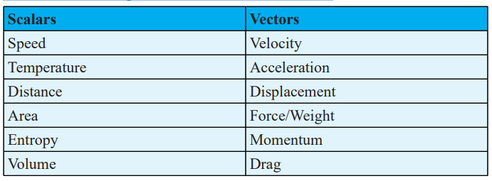
Turning effect of force
Moment of a force about a point
Every time we open a door, turn on a tap or tighten up a nut with a spanner,
we exert a turning force. The combined effect of the force and distance which
determines the magnitude of the turning force is called the moment of theforce or torque and is defined as follows:
“The moment (turning effect) of a force about a point is the force multiplied
by the perpendicular distance from the place where the force is applied to thatpoint.” Fig. a
Or Moment is force times lever arm where is the lever arm, and the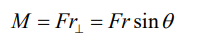
perpendicular symbolreminds us that we must use the distance from the
axis of rotation that is perpendicular to the line of action of the force (Fig.3.1a). The SI unit for moment is N m.
A lever arm or moment arm is the perpendicular distance from the axis ofrotation to a line drawn along the direction of the force.
An equivalent way of determining the torque associated with a force is to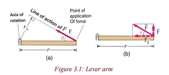
resolve the force into components parallel and perpendicular to the line that
connects the axis to the point of application of the force, as shown in Fig. 3.1b.
The component exerts no torque since it is directed at the rotation axis (its
lever arm is zero). Hence the torque will be equal to times the distance r fromthe axis to the point of application of the force:
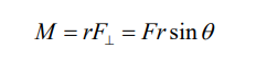
Activity 4
(i) Suspend a meter rule at its middle point, either by passing a string
through a hole or a knife edge. If necessary stick plasticine one one
and to make it balance exactly.
(ii) Tie loops of thread to several
(iii) Hang a 0.5 N weight A (the load) one the left hand side of the ruler
on the 34 cm mark (16 cm ) from the fulcrum)
(iv) Place another weight 0.2 N (the effort) on the other side and moveit until the ruler balances.
(v) Note the distances of the weights from the fulcrum, i.e from the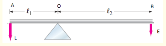
midpoint.(vi) Record the results in a suitable as shown in the table.
(vii) Reapeat several times with (a) the same weights in differentposition, and (b) different weights.
The table suggests that when the turning effects of forces acting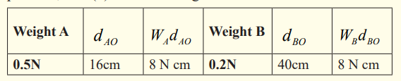
on an object are balanced the sum of clock wise moments is the
same as the sum of anticlockwise moments. This is the principle ofmoment
Principle of moment of force
When a body is in equilibrium (balanced), the sum of the anticlockwise
moments about any point is equal to the sum of the clockwise moments aboutthe same point.
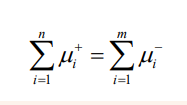
Example
In kinesiology (the study of human motion), it is often useful to know the
location of the center of mass of a person. This can be determined with
the arrangement shown fig A. A plank of weight 40 N is placed on two
scales separated by 2.0 m. A person lies on the plank and the left scale
reads 3214 N and the right scale reads 216 N as shown in fig B. What isthe distance from the left scale to the person’s center of mass?
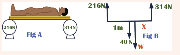
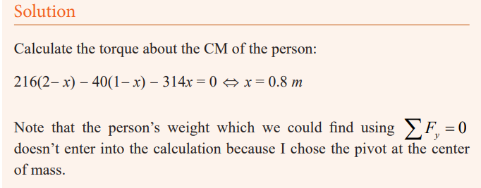
A torque is a quantity that measures the ability of a force to rotate an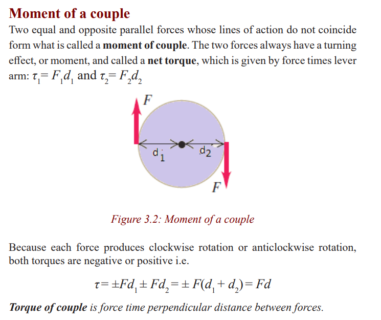
object around some axis. Net torque produces rotation. A torque is positive
or negative; depending on the direction the force tends to rotate an object.Torques that produce counterclockwise rotation are defined to be positive.
Example
A basketball is being pushed by two basketball players during tip-off.
Assuming each force acts perpendicular to the axis of rotation throughthe centre of ball the ball; find the net torque acting on the ball.
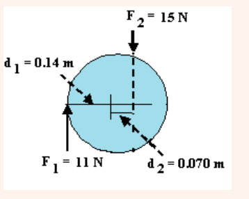
Torque should not be confused with work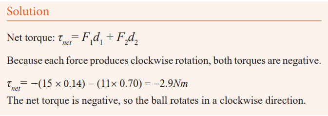
Torque (τ = Fd sin θ ) and work (W = Fd cos θ ) can both be expressed in
units of N m, so be careful to distinguish torque and work. The components of
a force that produces work is parallel to a distance (the displacement), while
the component of force that produces torque is perpendicular to a distance (thelever arm).
Torque should not be confused with force. Forces can cause a change in
linear motion, as described by Newton’s second law. Forces can also cause a
change in rotational motion, but the effectiveness of the forces in causing this
change depends on both the forces and the moment arms of the forces, in thecombination that we call torque.
If two or more forces are acting on a rigid object, as shown in Fig.3.3, each
tends to produce rotation about the pivot at O. We use the convention that the
sign of the torque resulting from a force is positive if the turning tendency
of the force is counterclockwise and is negative if the turning tendency isclockwise.
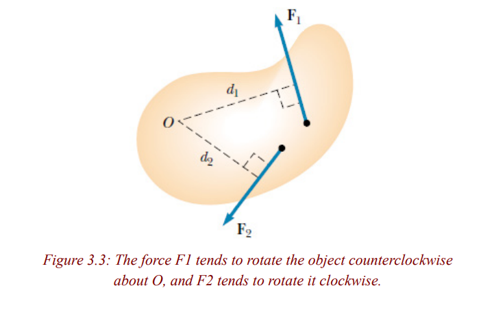
Equilibrium of a body
Conditions for equilibrium
Objects in daily life have at least one force acting on them (gravity). If they are
at rest, then there must be other forces acting on them as well so that the net
force is zero. A book at rest on a table, for example, has two forces acting on
it, the downward force of gravity and the normal force the table exerts upwardon it (Fig. 3.4).
Because the book is at rest, Newton’s second law tells us that the net force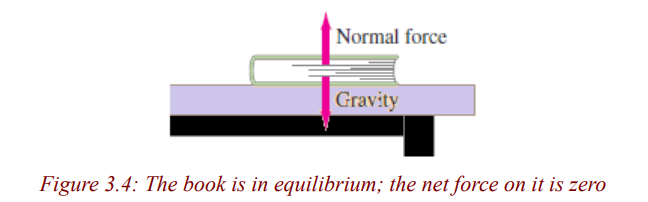
on it is zero. Thus the upward force exerted by the table on the book must be
equal in magnitude to the force of gravity acting downward on the book. Such
an object is said to be in equilibrium (Latin for “equal forces” or “balance”)
under the action of these two forces. This is often called the first conditionfor equilibrium (Fig.3.5a).
Force not only push or pull but have a turning-effect or moment about an
axis. In cases of equilibrium the moments have also to be considered. If forces
act at different points on an extended body an additional requirement must
be satisfied to ensure that the body has no tendency to rotate: The sum of the
torques about any point must be zero (Fig.3.5.b). This is called the secondcondition for equilibrium.
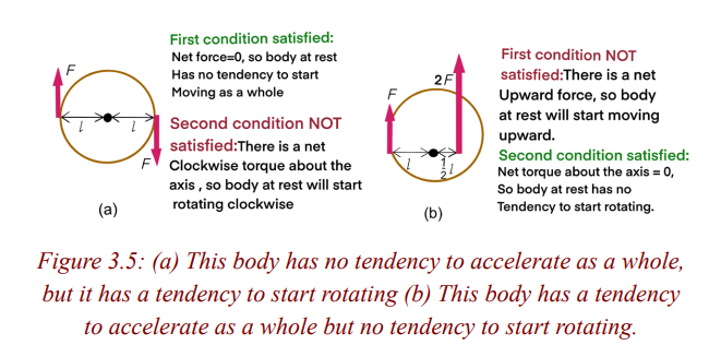
A rigid body is in mechanical equilibrium when the sum of all forces on all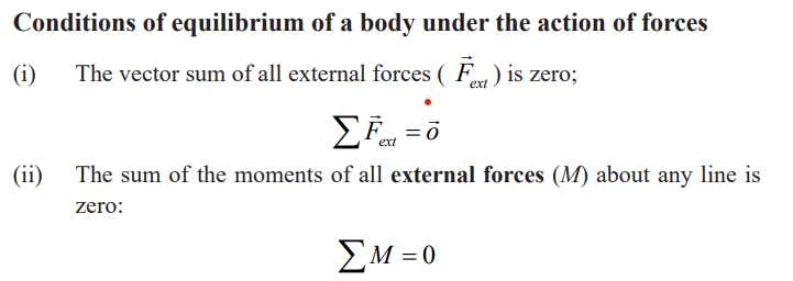
particles of the system is zero (i.e. when all the particles of the system are
at rest or that its center of mass moves with constant velocity relative to the
observer and the total force on each particle is permanently zero)., and also
the sum of all torques on all particles of the system is zero so that its state of
rotational motion remains constant. The bodies are rigid if they do not deformunder the action of applied forces.
We will apply the first and second conditions for equilibrium to situations
in which a rigid body is at rest (no translation or rotation). Such a body is
said to be in static equilibrium (Fig. 3.6). But the same conditions apply to
a rigid body in uniform translational motion (without rotation), such as an
airplane in flight with constant speed, direction, and altitude. Such a body is inequilibrium but is not static.
The above conditions of equilibrium are also used to determine the resultant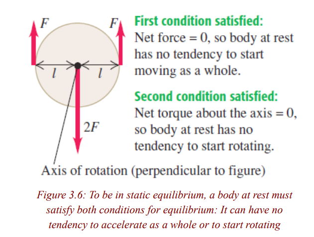
of non-parallel, non-concurrent systems of forces i.e. all of the lines of
action of the forces in this system do not meet at one point. The parallel force
system was a special case of this type. Since all of these forces are not entirely
parallel, the position of the resultant can be established using the graphical oralgebraic methods of resolving co-planar forces
There are a number of ways in which one could resolve the force system that
is shown. One graphical method would be to resolve a pair of forces using the
parallelogram or triangle method into a resultant. The resultant would then be
combined with one of the remaining forces and a new resultant determined,
and so on until all of the forces had been accounted for. This could prove to
be very complex if there are a great number of forces. The algebraic solution
to this system would potentially be simpler if the forces that are applied to thesystem are easy to break into components.
■ Addition of Forces in a Plane (Stevinus law)
If all the forces acting on a body act in a plane, they are called coplanar forces.
If they have a common point of application they are called concurrent forces
Consider a body that is subjected to two forces F1 and F2, whose lines of
action intersect at point A (Fig. 3.7). It is postulated that the two forces can
be replaced by a statically equivalent force R. This postulate is an axiom; it is
known as the parallelogram law of forces. The force R is called the resultant
of F1 and F2 . It is the diagonal of the parallelogram for which F1 and F2 areadjacent sides.
Now consider a system of n forces that all lie in a plane and whose lines of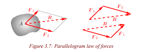
action intersect at point A (Fig. 3.8). Such a system is called a coplanar system
of concurrent forces. The resultant can be obtained through successive
application of the parallelogram law of forces. Mathematically, the summationmay be written in the form of the following vector equation:
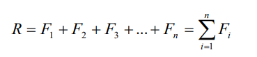
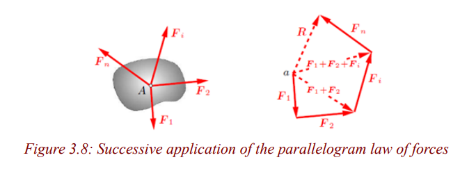
■ Representation in Cartesian Coordinates
It is usually convenient to resolve forces into two components that are
perpendicular to each other. The directions of the components may then be
given by the axes x and y of a Cartesian coordinate system (Fig. 3.8). The
quantities Fx and Fy are called the coordinates of the vector F or componentsof F.
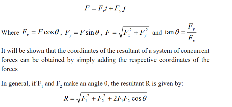
Examples
1. A hiker begins a trip by first walking 25.0 km southeast from her car.
She stops and sets up her tent for the night. On the second day, she
walks 40.0 km in a direction 60.0° north of east, at which point she
discovers a forest ranger’s tower.
(a) Determine the components of the hiker’s displacement for each
day.
(b)Determine the components of the hiker’s resultant displacement
R for the trip. Find an expression for R in terms of unit vectors.(c) Determine the magnitude and direction of the total displacement.
Solution
(a) If we denote the displacement vectors on the first and second days by
A and B, respectively, and use the car as the origin of coordinates, weobtain the vectors shown in Figure below.

2. Under what circumstances would a nonzero vector lying in the xy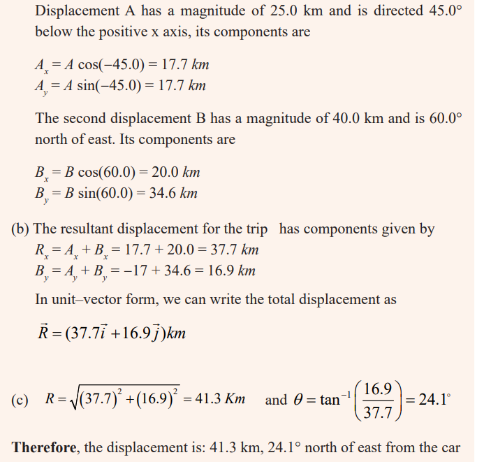
plane have components that are equal in magnitude?
Solution
Any vector that points along a line at 45° to the x and y axes has componentsequal in magnitude.
3. In what circumstance is the x component of a vector given by themagnitude of the vector times the sine of its direction angle?
Solution
If the direction of a vector is specified by giving the angle of the vector
measured clockwise from the positive y-axis, then the x-component of the
vector is equal to the sine of the angle multiplied by the magnitude of thevector.
4. If A = B, what can you conclude about the components of A and B?
Solution
Any vector that points along a line at 45° to the x and y axes has componentsequal in magnitude.
■ Lami’s theorem
Lami’s theorem gives the conditions of equilibrium for three forces acting at
a point O. Lami’s theorem states that if three forces acting at a point are in
equilibrium, then each of the force is directly proportional to the sine of theangle between the remaining two forces.
Branch of mechanics which deals with state of equilibrium is called statics.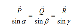
Statics is the branch of mechanics concerned with the analysis of loads
(force, torque/moment) on physical systems in static equilibrium, that is, in
a state where the relative positions of subsystems do not vary over time, or
where components and structures are at a constant velocity. When in static
equilibrium, the system is either at rest, or its center of mass moves at constant
velocity. The study of moving bodies is known as dynamics, and in fact theentire field of statics is a special case of dynamics.
Stability and Balance
An object in static equilibrium, if left undisturbed, will undergo no translational
or rotational acceleration since the sum of all the forces and the sum of all the
torques acting on it are zero. However, if the object is displaced slightly, threeoutcomes are possible:
• Equilibrium is said to be stable if small, externally induced
displacements from that state produce forces that tend to oppose the
displacement and return the body or particle to the equilibrium state.
Examples include a weight suspended by a spring or a brick lying on alevel surface.
• Equilibrium is unstable if the least departure produces forces that tend
to increase the displacement. An example is a ball bearing balanced onthe edge of a razor blade.
• Static Equilibrium (neutral equilibrium) is equilibrium where
all forces are balanced, but it also applies to bodies in uniform or
accelerated motion. For example, a book resting on a table applies a
downward force equal to its weight on the table. According to the third
law, the table applies an equal and opposite force to the book. This
force occurs because the weight of the book causes the table to deformslightly so that it pushes back on the book like a coiled spring.
By summing up
• A system is said to be in stable equilibrium if, when displaced from
equilibrium, it experiences a net force or torque in a direction oppositethe direction of the displacement.
• A system is in unstable equilibrium if, when displaced from equilibrium,
it experiences a net force or torque in the same direction as thedisplacement from equilibrium.
• A system is in neutral equilibrium if its equilibrium is independent ofdisplacements from its original position.
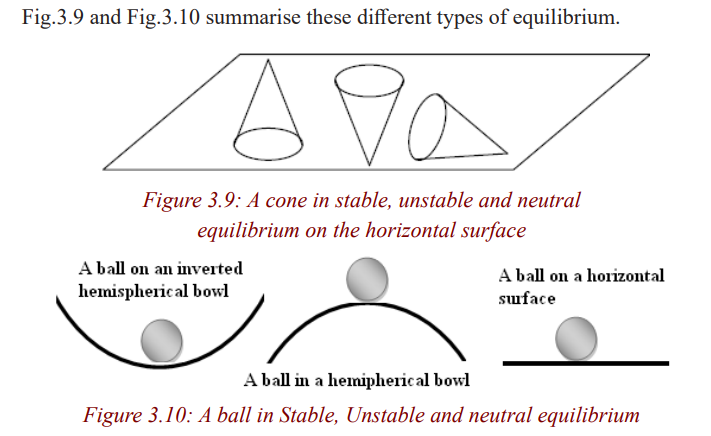
Centre of gravity and center of mass
Concept of centre of gravity and center of mass
The center of gravity is the average location of the weight of an object. The
centre of gravity is defined as the point of application of the resultant force
due to the earth’s attraction on it. The center of gravity is a geometric propertyof any object.
The centre of gravity of a body also coincides with its centre of mass. The
center of mass of an object may be defined as the point at which an appliedforce produces acceleration but no rotation
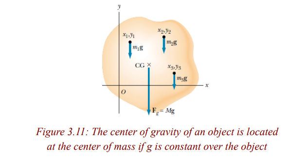
Centre of gravity and base of support of a body
1. For balance to exist, the line of gravity must intersect the base of support.
2. If the area of the base of support of an object is increased, this tends to
increase the stability of the object.
3. The lower the center of gravity is above the base of support the more
stable the object tends to be. (This is true even though the size of the
base of support is unchanged.)
4. Objects that are more massive tend to be more stable.
5. For an object, the farther the line of gravity’s intersection is from the
edge of its base of support the more stable the object tends to be in that
direction.Determining the center of gravity
Determining the center of gravity is very important for any flying object. In
general, determining the center of gravity (cg) is a complicated procedure
because the mass (and weight) may not be uniformly distributed throughout the
object. If the mass is uniformly distributed, the problem is greatly simplified.
If the object has a line (or plane) of symmetry, the center of gravity lies on theline of symmetry.
For a solid block of uniform material, the center of gravity is simply at theaverage location of the physical dimensions.
Example
Activity 5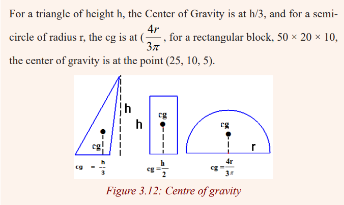
To determine the centre of gravity of different regular shapes
Apparatus* Manila paper, scissors, a pencil and a ruler
Procedure• Make a number of shapes from a manila paper, as below:
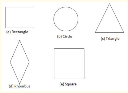
• Find the centre of gravity of those different figures.
Conclusion
The point of intersection of diagonals (a,d and e), bisectors (c) ,diameters(b) is the centre of gravity of those figures
For a general shaped object, there is a simple mechanical way to determinethe center of gravity:
In Step 1, you hang the object from any point and you drop a weighted string(plumb line) from the same point. Draw a line on the object along the string.
For Step 2, repeat the procedure from another point on the object you now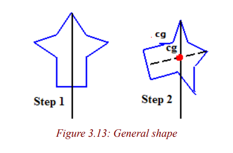
have two lines drawn on the object which intersect. The center of gravity is
the point where the lines intersect. This procedure works well for irregularlyshaped objects that are hard to balance.
Activity 6
To determine the centre of gravity of an irregularly shaped lamina
Apparatus* A plumb line, a thread, a stand and a cardboard
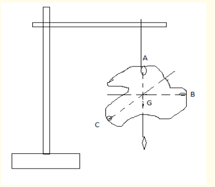
Procedure
• Make 3 holes, A, B and C on the edges the cardboard.
• Suspend it by a rod through the hole A as shown in Figure2.4
• Tie a plumb line on the rod beside the cardboard.
• After the cardboard and plumb line have stopped swinging, draw
a vertical line on the cardboard as set by plumb line.
• Repeat the experiment using other holes B and C. The lines
intersect at a point noted G
• Balance the cardboard with the tip of a pencil at the point ofintersection of the three lines. What do you observe?
Observation
The suspended object will always rest with its centre of gravity vertically
below the point of support. The object balances on the tip of the pencil ifplaced at its centre of gravit.
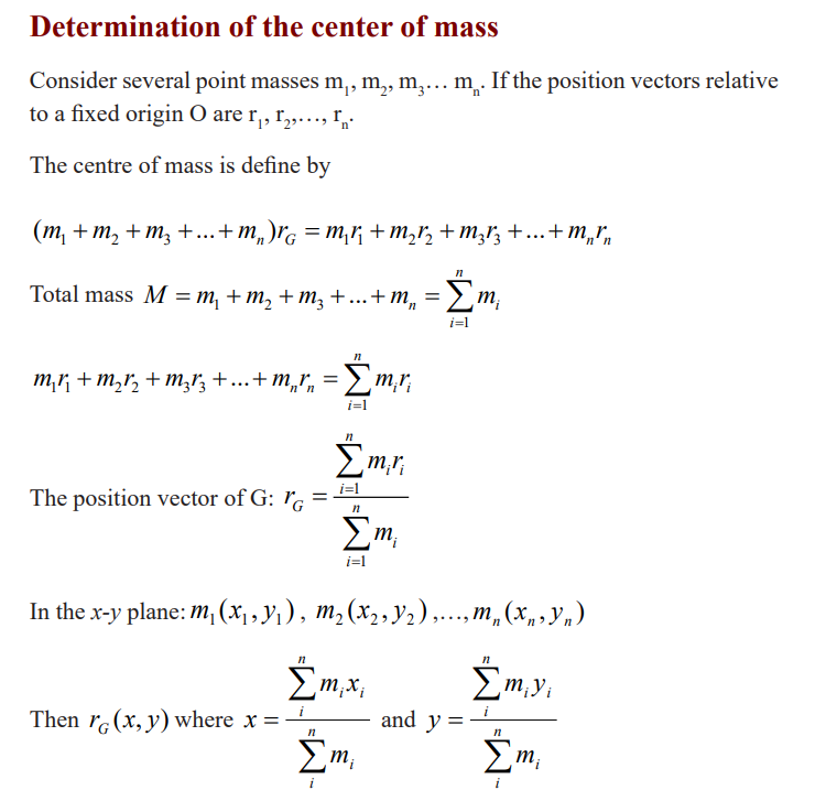
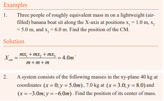
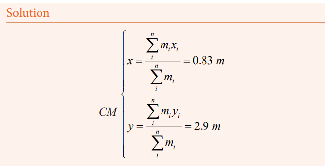
Stability and center of gravity
Consider a ball suspended freely from a string is in stable equilibrium, for if it
is displaced to one side, it will return to its original position (Fig. 3.14a) due
to the net force and torque exerted on it. On the other hand, a pencil standing
on its point is in unstable equilibrium. If its center of gravity is directly over
its tip (Fig. 3.14b), the net force and net torque on it will be zero. But if it
is displaced ever so slightly as shown—say, by a slight vibration or tiny air
current—there will be a torque on it, and this torque acts to make the pencil
continue to fall in the direction of the original displacement.
Finally, an example of an object in neutral equilibrium is a sphere resting on a
horizontal tabletop. If it is moved slightly to one side, it will remain in its newposition—no net torque acts on it.
In general, an object whose center of gravity (CG) is below its point of support,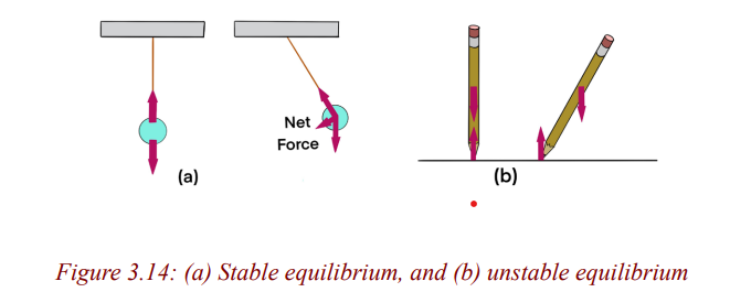
such as a ball on a string, will be in stable equilibrium. Consider a standing
refrigerator (Fig. 3.15a). If it is tipped slightly, it will return to its original
position due to the torque on it as shown in Fig. 3.15b. But if it is tipped too
far, Fig. 3.15c, it will fall over. The critical point is reached when the CG shifts
from one side of the pivot point to the other.When the CG is on one side, the
torque pulls the object back onto its original base of support, Fig. 3.15b. If the
object is tipped further, the CG goes past the pivot point and the torque causesthe object to topple, Fig. 3.15c.
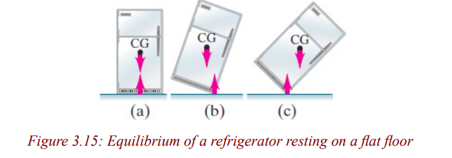
In general,
• an object whose center of gravity is above its base of support will be
stable if a vertical line projected downward from the CG falls within the
base of support. This is because the normal force upward on the object
(which balances out gravity) can be exerted only within the area of
contact, so if the force of gravity acts beyond this area, a net torque will
act to topple the object.
• the larger the base and the lower the CG, the more stable the object.
• an object tends to fall when its center of gravity is away from the basethat supports it.
Applications of equlilibrium
Tower Crane – Method of Joints
The tower crane shown in the figure below consists of tower DCE fixed at the
ground and two jibs AC and CB. The jibs are supported by tie bars AD and
DB, and are assumed to be attached to the tower by pinned connections. Thecounterweight WC weighs and the crane has a lifting capacity of W.
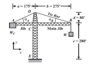
Beam balance
It consist of pivoted horizontal lever of equal length arms called the beam,
with a weighing pan also called scale, scale pan or boson, suspended fromeach arm.
The unknown mass is placed on one pan and standard masses are added on the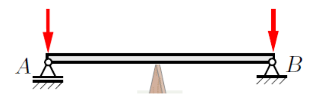
other pan until is as close to equilibrium as possible. In precision balances a
slider mass is moved along a graduated scale. The slider position gives a finecollection to the mass value.
Example
A uniform meter stick supported at the 25 cm mark is in equilibrium
when a 1 kg rock is suspended at the 0 cm end (as shown in Fig.). Is the
mass of the meter stick greater than, equal to, or less than the mass of therock? Explain your reasoning.
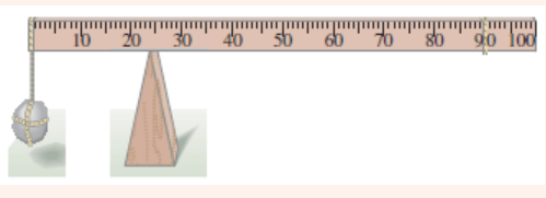
Solution
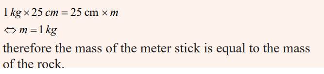
Application Activity 3.3
A friend of yours that has been sick comes from the hospital where he
had gone for medication telling you that he is 62 kg and that is what is
indicated on his medical papers.
Imagine you have the following
* A strong wood bar of a bout 5m (or any length as long as you know
its actual length) and has a mass of 10kg.
* A wood that you can use as a pivot
a)Since you know the exact mass of your friend and that of the
wood. Explain all the procedures you can follow to know your
mass. In your procedures include all the necessary equations and
diagrams you may need to use.
b)Do you think the mass (your mass) you obtained is accurate?
Explain your reasoning.
c)What do you think may be the source of errors in determining
your mass? Or any unknown mass?
d)Basing on your knowledge and understanding you have obtained
from this unit, how can this unit be applied in your career you arepursuing?
END UNIT ASSESSMENT
1. The uniform bar shown below weighs 40 N and is subjected to the
forces shown. Find the magnitude, location, and direction of the forceneeded to keep the bar in equilibrium.
2. System given below is in equilibrium. If the potential energies of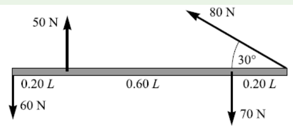
objects A and B are equal, find the mass of object A in terms of G.(Rod is homogeneous and weight of it is G.)
A 172 cm tall person lies on a light (massless) board which is sup-ported by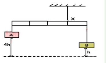
two scales, one under the top of her head and one beneath
the bottom of her feet see Fig. The two scales read respectively 35.1
kg and 31.6 kg. What distance is the center of gravity of this personfrom the bottom of her feet?
3. A) A seesaw consisting of a uniform board of mass M =10kg and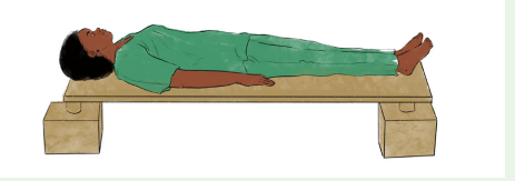
length l=2m supports a father and daughter with masses mf and md, 50and 20kg respectively as shown in the Figure below.
The support (called the fulcrum) is under the center of gravity of the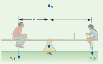
board, the father is a distance d from the center, and the daughter is adistance l / 2 from the center.
a. Determine the magnitude of the upward force n exerted by thesupport on the board.
b. Determine where the father should sit to balance the system.
B) Three children are trying to balance on a seesaw, which consists of
a fulcrum rock, acting as a pivot at the center, and a very light board3.6 m long (see fig.).
Two playmates are already on either end. Boy A has a mass of 45 kg, and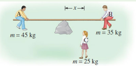
girl B a mass of 35 kg. Where should girl C, whose mass is 25 kg, placeherself so as to balance the seesaw?
4. A uniform 1500kg beam, 20m long, supports a 15,000kg printing press
5 from the right support column, see the figure. Calculate the force oneach of the vertical support columns.
5. A horizontal rod AB is suspended at its ends by two strings. (See the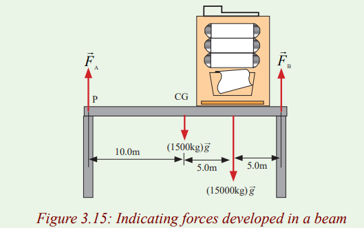
figure below). The rod is 0.6m long and its weight of 3N acts at Gwhere AG is 0.4m and BG is 0.2m. Find the tensions X and Y
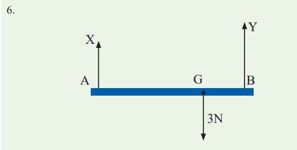
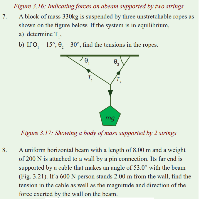
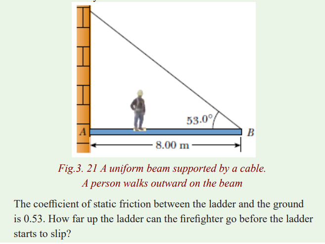
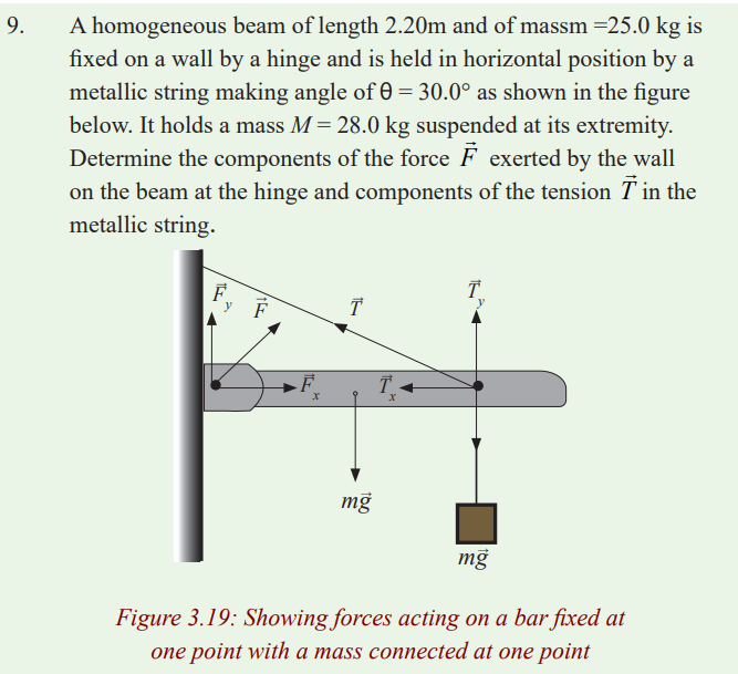
Unit 4 Work, Energy and Power
Key Unit Competence
Evaluate the relation between work, energy and power and the resulting
phenomena.
My goals
By the end of this unit, I will be able to:
* define work done, energy and power.
* state the formulae of work, energy and power.
* explain how power depends on energy.
* explain how gravitational potential energy.
* identify the difference between potential energy and kinetic energy
* describe strain and work done in deforming materials
INTRODUCTORY ACTIVITY
Kaliza and Kalisa are classmates in senior four sciences. When Kaliza
mops the class alone; she can do it in only 30 minutes. But when Kalisa
is given the same task of mopping the class, he can do it in 45 minutes.
Questions
1. Discuss the work being done as in the above case study. In your own
words define the term work.
2. Sometimes people do confuse the term work and energy. Are they
different? Are they the same? Explain your choice.
3. Between Kaliza and Kalisa who is more powerful? Why?
4. By research find the meaning of the terms: Work, energy and power
Introduction
In real life, we always use the term work. Which means “task to be
accomplished. But before the task to be done, one must have energy. Then if
a given work is done in a given time, we say that one has power i.e work done
in a given time.
Work
Review of the idea of work
Activity 1
Study and interprete the diagram below
CASE I
Work is done when a force moves its point of application along the
direction of its action.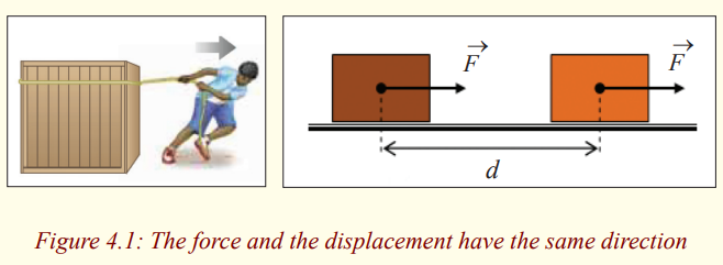
* How is the force applied onto the body?
* Why does it change its position?
* What if the body is 10 times the mass of the boy. Would the body
change its position? Why?
* State the direction of application of force.
From the fig. 4.1 and your deductions, how can you define Work?
CASE II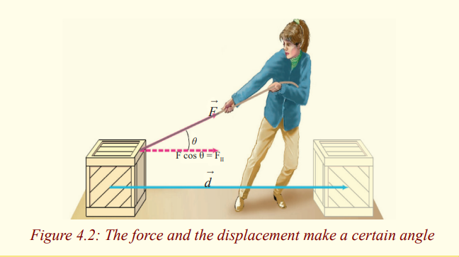
Activity 2
Aim; To relate distance, force and work
Let us as a class visit any where people are constructing a house,a bride,
road.
Ask them why they are paid?
Ask them how they measure what they do.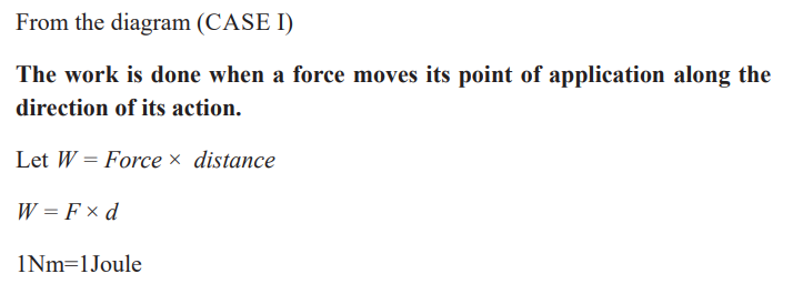
Expressions of some kinds of work
Work of the gravitational force
Activity 3
a) Hold a book in your hands at a height say h.
b) Leave it to fall vertically onto the ground.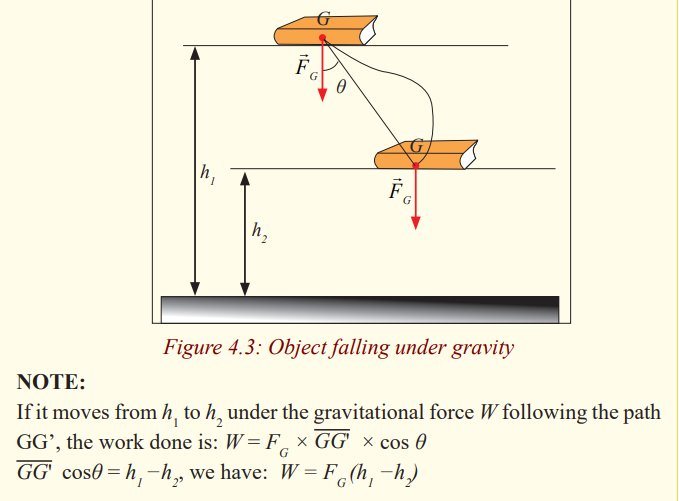
From the deductions, it can be noted that:
The work done by the gravitational force does not depend on the path
followed but on the change of the height.
Work done by the force of pressure
Activity 4
Requirements
* A syringe with a piston.
Aim: To determine work done by a piston.
* Pull the piston through a small distance ∆x as shown in the figure below.
Assuming you applied a force F, What is the work done?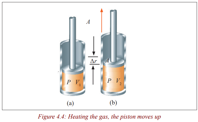
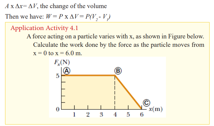
Energy
Activity 5
Ask yourself why some times you feel like not working or bored. What
do you normally say when you are asked why you are not performing any
duty? Use what comes into your mind to define energy.
Normally we say that Energy is ability of a body to do work.
It’s measured in Joules like work. When an interchange of energy occurs
between two bodies, we can consider the work done as a measure of the
quantity of energy transferred between them. It has the same units as work
and heat i.e. Joule.
The displacement is that of the point of application of the force. If the
force is applied to a particle or a non-deformable, non-rotating system, this
displacement is the same as the displacement of the particle or system. For
deformable systems, however, these two displacements are often not the same.
Force is not necessarily the cause of the object’s displacement. For example,
if you lift an object, work is done by the gravitational force, although gravity
is not the cause of the object moving upward! An important consideration
is that work is an energy transfer. If W is the work done on a system and W
is positive, energy is transferred to the system; if W is negative, energy is
transferred from the system. Whenever work is done energy is transferred or
converted from one form to another. Work is performed not only in motion and
displacement (mechanical work); it is done also by fire flame and electricity
in electric lamps.
Example
The gravitational force exerted by the Sun on the Earth holds the Earth in
an orbit around the Sun. Let us assume that the orbit is perfectly circular.
The work done by this gravitational force during a short time interval in
which the Earth moves through a displacement in its orbital path is
(a) zero (b) positive (c) negative (d) impossible to determine.
Solution
(a). The force does no work on the Earth because the force is pointed
toward the center of the circle and is therefore perpendicular to the
direction of the displacement.
Categories of Energy in Our Environment
There are several forms of energy in our environment e.g. mechanical energy,
heat energy, light energy, electromagnetic energy, electric energy, nuclear
energy, sound energy, chemical energy stored in petrol, food and other
materials, moving matter such as water, wind, falling rocks, etc.
Furthermore, one form of energy can be converted to another. For example,
when an electric motor is connected to a battery, the chemical energy in the
battery is converted to electrical energy in the motor, which in turn is converted
to mechanical energy as the motor turns some device.
Scientists classify forms of energy into two major categories: Potential energy
and Kinetic energy.
Potential energy
Activity 6
How do we know that things have energy just because of their height?
Well, let’s think about the following process:
1. You lift a ball off the ground until it is above your head.
2. You drop it.
3. It is moving fast right before it hits the ground.
4. Draw a conclusion.
Potential energy may be defined as the energy possessed by an objects or
bodies due to their position or state of strain or the position of their parts.
Potential energy is energy deriving from position. Potential energy is referred
to as stored energy because it can be looked at as energy which will be used
when time comes for it to be used. Thus a stretched rubber band has elastic
potential energy.
Kinds of potential energy:
a) Chemical potential energy
Activities such as tug of war or riding a bicycle, we use energy provided by
the food we eat. In cars or motorcycles, petrol is used to provide energy. Petrol
contains energy which makes these vehicles move. Food and petrol contain
energy called chemical potential energy. It is called chemical energy because
it is from the chemical bonds found in the food or petrol it is potentially
available for use when it is needed.
b) Elastic potential energy
Restoring force
A block on a horizontal, frictionless surface is connected to a spring. If the
spring is either stretched or compressed a small distance from its unstretched
(equilibrium) configuration, it exerts on the block a force that can be expressed
as F = −k x
x is the position of the block relative to its equilibrium (x = 0) position
• k is a positive constant called the force constant or the spring
constant of the spring. The units of k are N/m.
• The negative sign in Equation signifies that the force exerted by
the spring is always directed opposite to the displacement from
equilibrium.
This force law for springs is known as Hooke’s law. Because the spring force
always acts toward the equilibrium position (x = 0), it is sometimes called a
restoring force.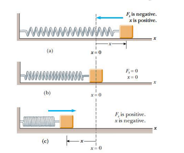
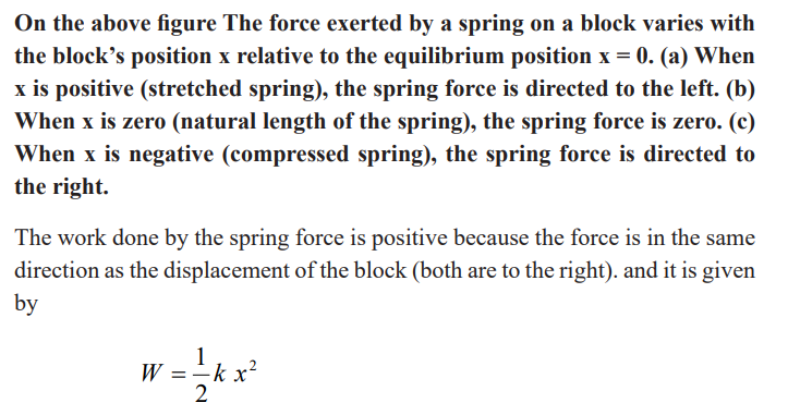
Elastic Potential Energy
Activity 7
Aim; To find out whether there is energy stored in elastic Materials
In laboratory,
* Try to perform experiment arranging your apparatus as shown in the
figure below.
* What do you observe after putting a mass on the spring.
* What would happen if the mass of the body is given a small
displacement downwards?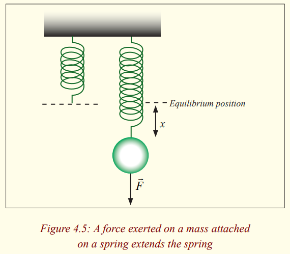
The elastic potential energy of the system can be thought of as the energy
stored in the deformed spring (one that is either compressed or stretched from
its equilibrium position.
Consider Figure below, which shows a spring on a frictionless, horizontal
surface.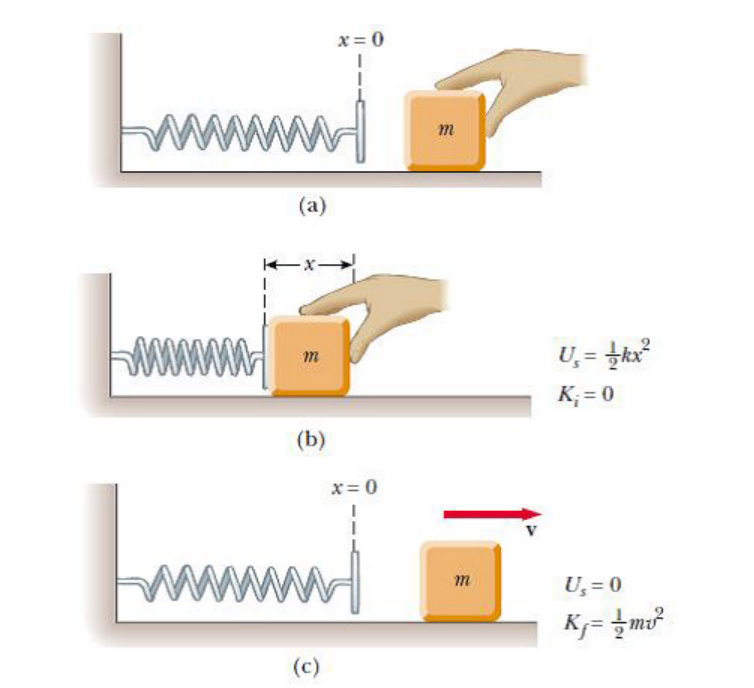
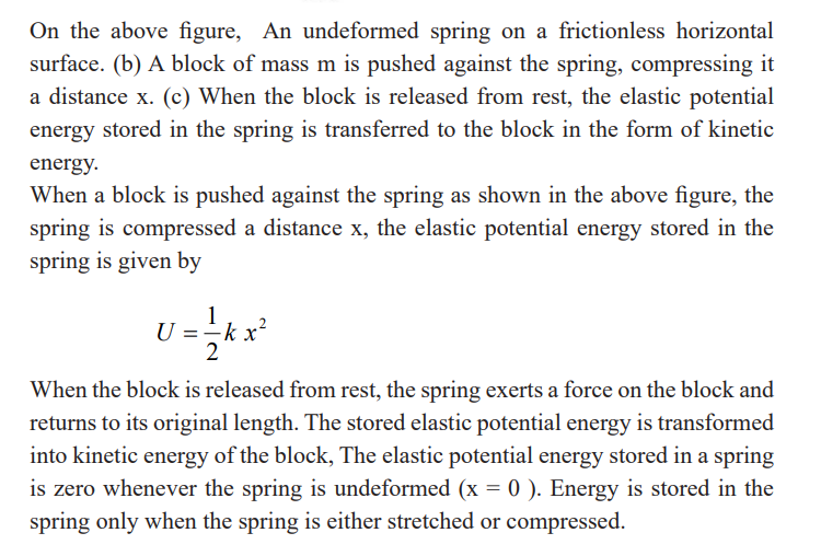
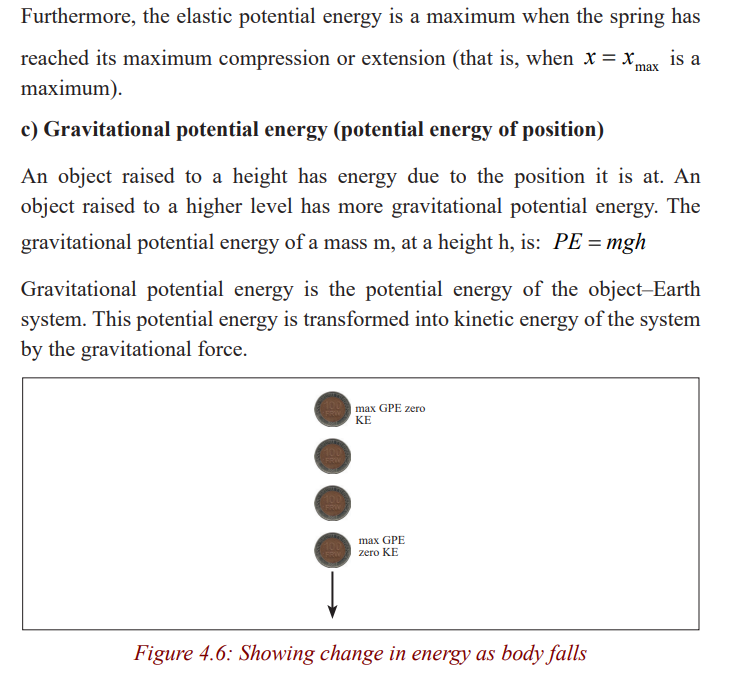
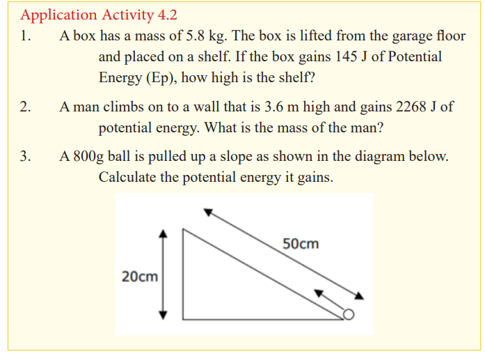
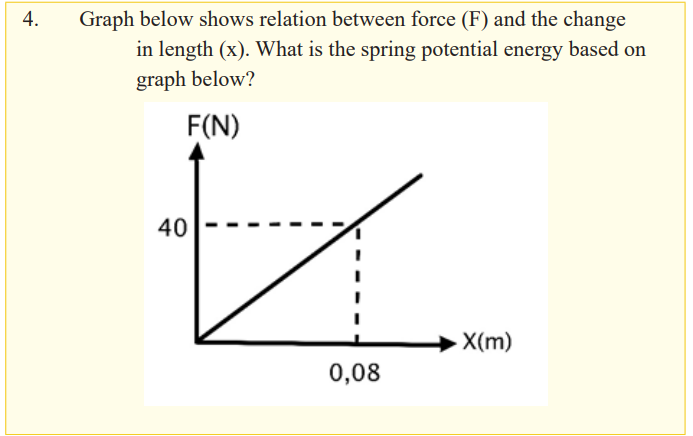
Kinetic energy
Kinetic energy is the form of energy possessed by moving bodies. Such bodies
have the ability to do work e.g. a flying bullet can kill a dangerous wild animal.
Wind (a moving mass of air) flowing streams, falling rocks, heat flowing from
a body at high temperature to one at a lower temperature, electricity (flowing
electrons), moving cars, lorries, busses, etc, all have kinetic energy. Kinetic
energy of a body is dependent upon both the body’s mass and speed.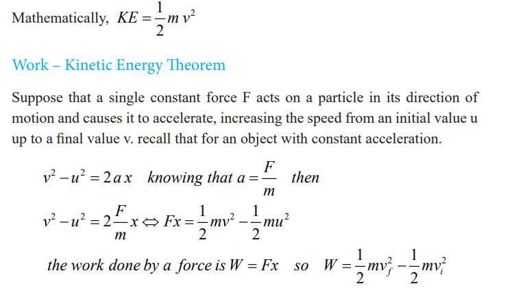
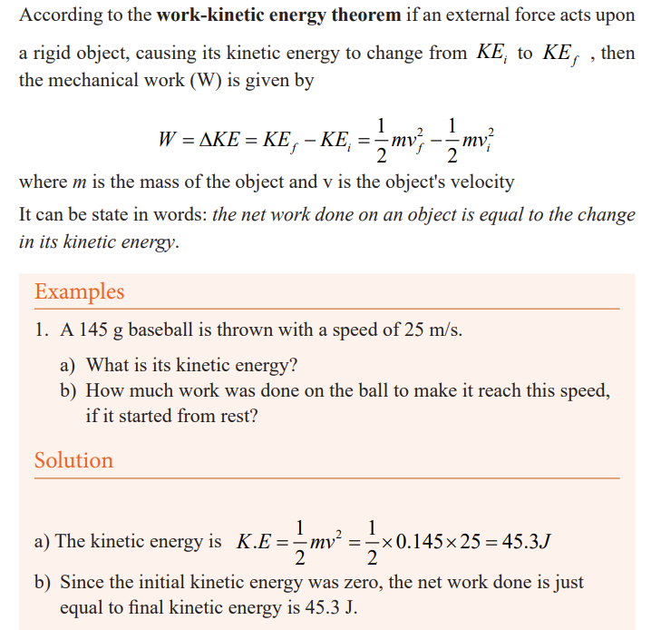
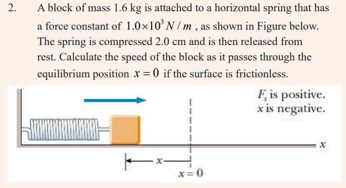
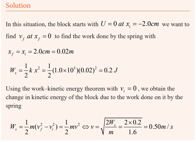
Total Mechanical energy
Mechanical energy can be either kinetic energy (energy of motion) or potential
energy (stored energy of position). Objects have mechanical energy if they are
in motion and/or if they are at some position relative to a zero potential energy
position (for example, a brick held at a vertical position above the ground or
zero height position).
We call Mechanical energy is the sum of kinetic energy and all forms of potential
energy associated with an object or group of objects i.e. E PE KE = +Conservation of mechanical energy
If a body of mass m is thrown vertically upwards with an initial velocity v0 atA, it has to do work against the constant force of gravity.
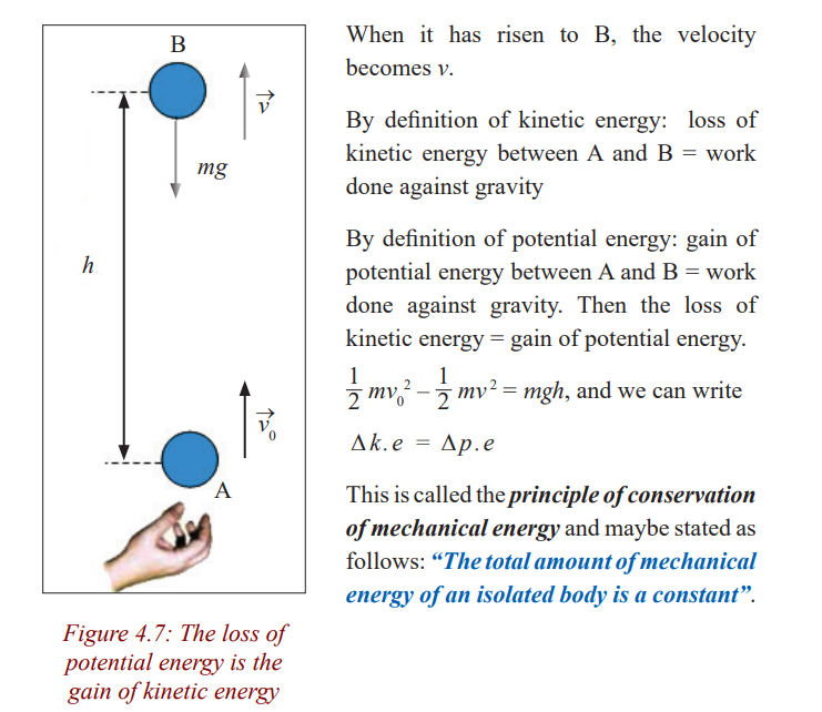
Example
A 6.0 kg block initially at rest is pulled to the right along a horizontal by
a constant horizontal force of 12 N; Find the speed of the block after it
has moved 3.0 m.
a) If the surfaces in contact is frictionless surface.
b) If the surfaces in contact have a coefficient of kinetic friction of
0.15.
c) Suppose the force F is applied at an angle as shown in( Fig.b).
At what angle should the force be applied to achieve the largest
possible speed after the block has moved 3.0 m to the right?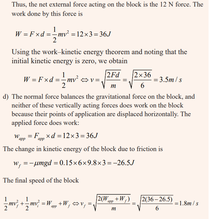
Power
Activity 8
Interpret the diagrams below
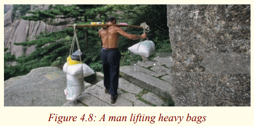

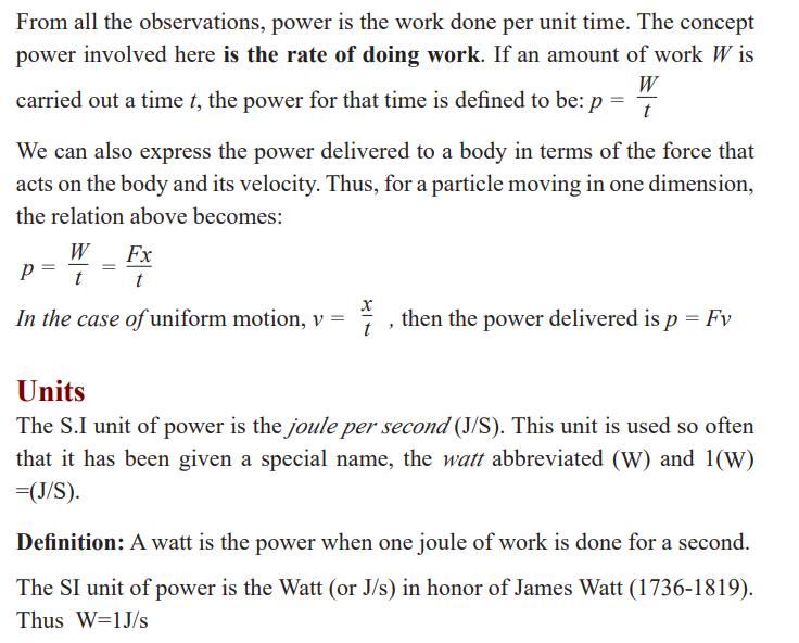
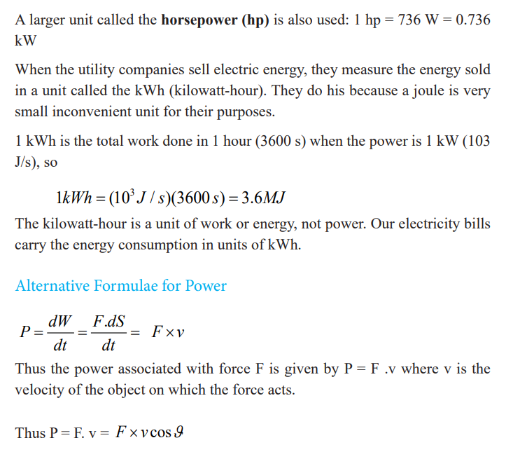
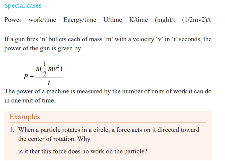
Solution
The force is perpendicular to every increment of displacement. Therefore,
p mv =
2. Discuss whether any work is being done by each of the following
agents and, if so, whether the work is positive or negative: (a) a
chicken scratching the ground, (b) a person studying, (c) a crane
lifting a bucket of concrete, (d) the gravitational force on the bucket
in part (c), (e) the leg muscles of a person in the act of sitting down.Solution
(a) Positive work is done by the chicken on the dirt.(b) No work is done,
although it may seem like there is. (c) Positive work is done on the bucket.
(d) Negative work is done on the bucket. (e) Negative work is done on theperson’s torso.
3. When a punter kicks a football, is he doing any work on the ball
while his toe is in contact with it? Is he doing any work on the ball
after it loses contact with his toe? Are any forces doing work on theball while it is in flight?
Solution
Yes. Force times distance over which the toe is in contact with the ball.
No, he is no longer applying a force. Yes, both air friction and gravity dowork.
4. Cite two examples in which a force is exerted on an object withoutdoing any work on the object.
Solution
Force of tension on a ball rotating on the end of a string. Normal forceand gravitational force on an object at rest or moving across a level floor.
5. As a simple pendulum swings back and forth, the forces acting on
the suspended object are the gravitational force, the tension in the
supporting cord, and air resistance. (a) Which of these forces, if
any, does no work on the pendulum? (b) Which of these forces does
negative work at all times during its motion? (c) Describe the workdone by the gravitational force while the pendulum is swinging.
Solution
a) Tension (b) Air resistance (c) Positive in increasing velocity on thedownswing.
Negative in decreasing velocity on the upswing.
Everyday usage of the term momentum is in accord with the definition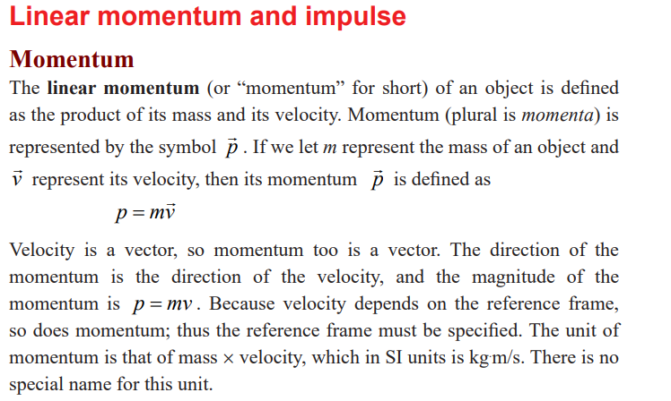
above. According to the equation of momentum, a fast-moving car has more
momentum than a slow-moving car of the same mass; a heavy truck has
more momentum than a small car moving with the same speed. The more
momentum an object has, the harder it is to stop it, and the greater effect it will
have if it is brought to rest by striking another object. A football player is more
likely to be stunned if tackled by a heavy opponent running at top speed than
by a lighter or slower-moving tackler. A heavy fast-moving truck can do moredamage than a slow-moving motorcycle.
Momentum (symbol: p) of an object is the product of the mass and velocityof a moving body.
Example
Calculate the linear momentum of the car in the figure below.
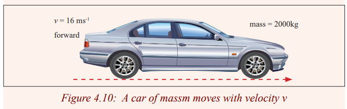
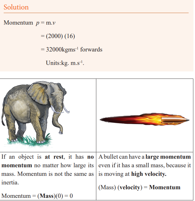
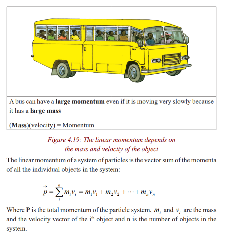
Example
A 2250 kg pickup truck has a velocity of 25 m/s to the east. What is themomentum of the truck?
Solution
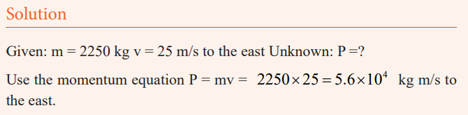
Conservation of momentum
Activity 9: Field work
As a class, visit a place with a pool table.
Let each and every body try to hit the ball using the playing stick.
What happens when one ball hits another?
State and observe what you notice.Draw a conclusion.
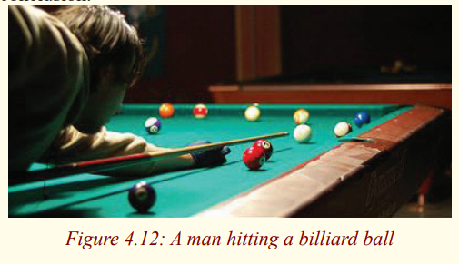
Activity 10: Fieldwork
* As a class, visit a place where there is billiard.
* Try to arrange the balls with the help of your teacher or any of the
learners who have ever played it.
* Let one of you hit the white ball to strike/hit the rest.
* State what you observe after the white ball has hit the balls.
* Draw your conclusion from your observations.* Repeat the same procedures using balls in the play grounds.
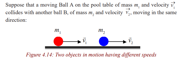
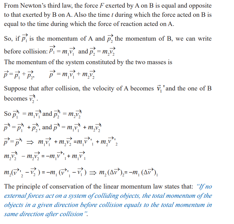
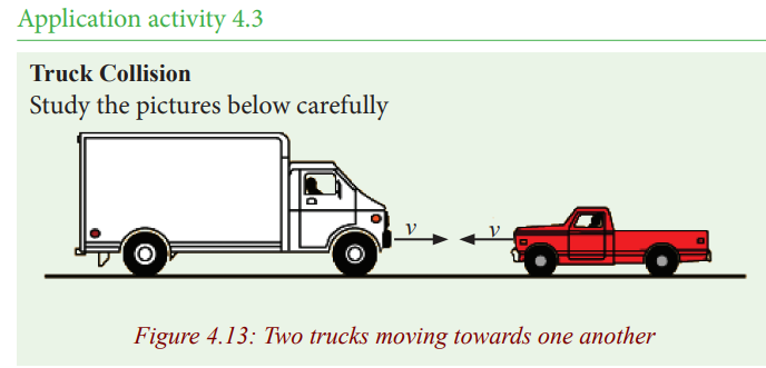
In a head-on collision:
1. Which truck will experience the greatest force?
2. Which truck will experience the greatest change in momentum?
3. Which truck will experience the greatest change in velocity?
4. Which truck will experience the greatest acceleration?5. Which truck would you rather be in during the collision?
Impulse
Activity 11
* Move out the class to the play ground.
* In pairs (one pair at a time), kick a ball so that it is moving with a
low speed. Let your friend stop it. Ask him/her what he/she felt. Let
your friend do the same.
* For the second time, make sure that you kick the ball by applying a
strong force so that it moves faster. Let your friend try to stop it. Ask
him/her what this time he/she has felt?
* Go back in class and summarise what you observed and felt while inthe play ground.
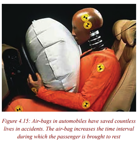
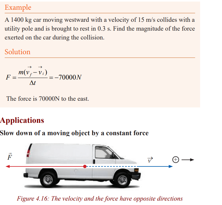
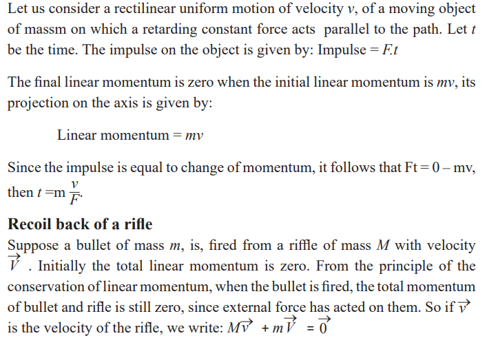
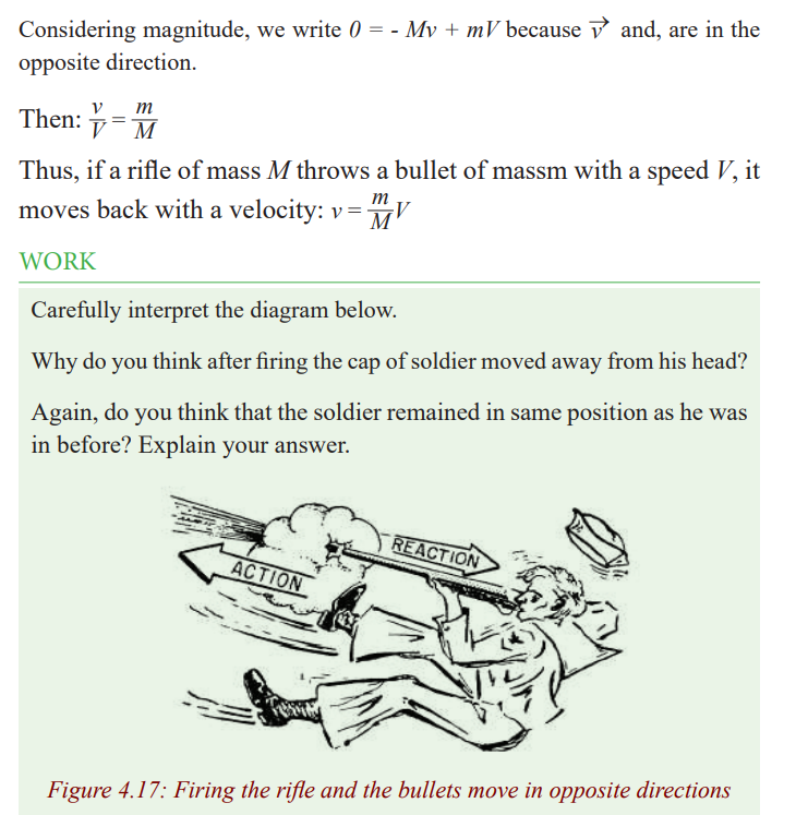
Application activity 4.5
1. Two bodies of mass 3kg and 5kg travelling in opposite directions
on a horizontal surface collide. The velocities of the bodies before
collision are 6m/s and 5m/s respectively. Given that after collision
the two separate and move in the same direction in which the 5kg
body was moving before collision, and the velocity of the 5kg mass
is 1m/s, find the speed of the 3kg body after impact. Find also theloss in the energy.
2. A body of mass 2kg initially moving with a velocity of 1m/s is
acted upon by a horizontal force of 6N for 3seconds. Find
(i) Impulse given to the body(ii) Final speed of the body
Collisions
Activity 12
To know what happens to bodies after impact/colliding.
To know the effect of collision on the velocities and masses of bodies aftercolliding.
Observe the diagram below carefully assuming the black car to have alarger mass than a white one and answer the questions that follow.
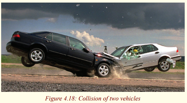
Questions about the picture above:
a) Do you think after collision , the two cars continue moving?
Explain why?
b) From what you observed, what is the effect of collision?
c) After separating the cars, do you think the masses of thecars changed? Explain why.
Note: We can define collision as an interaction between bodies in
which the time intervals during which the bodies interactionis small relative to the time for which we can observe them.
In collision the total momentum of colliding objects is always conserved.
Usually, however, their total kinetic energy is not conserved; some of it is
changed to heat or sound energy, which is recoverable. Such collisions aresaid to be inelastic.
For example, when a lump of putty falls to the ground, the total momentum of
putty and earth is conserved, that is, the putty loses momentum and the earth
gains an equal amount of momentum. But all the kinetic energy of putty ischanged to heat and sound on collision.
An Inelastic collision is the collision where the total kinetic energy is not
conserved (total momentum always conserved in any type of collision). If the
total kinetic energy is conserved, the collision is said to be elastic. For example,the collision between two smooth smoker balls is approximately elastic.
Elastic collision
In here, we shall consider objects colliding in a straight line and thereafterthey move with different speeds in the same direction.
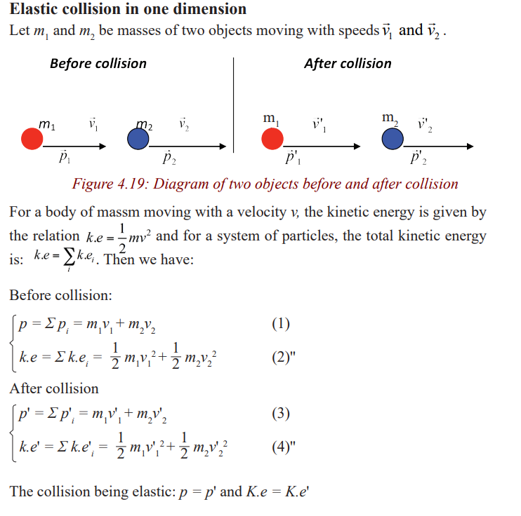
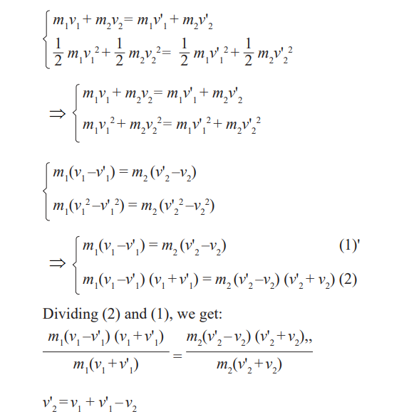
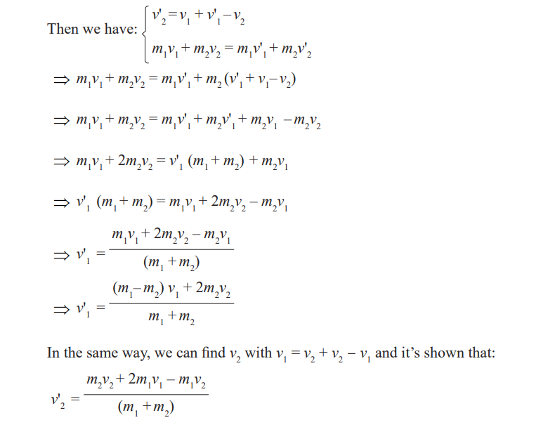
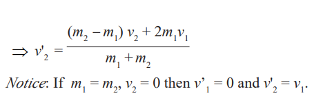
Special cases:
• Consider the case when the mass of one body, is equal to that of the
other. And the particle 2 is initially at rest, when they collide the velocity
of the first become zero and the velocity of the second is equal to thevelocity of the first one before collision.
That is a heavy particle collides with head-on with alight one that is at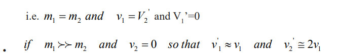
rest , heavy particle continue its motion unaltered after the collision and
the light particle rebounds with a speed equal to about twice the initial
speed of the heavy particle. an example of such collision would be that
of the moving heavy atom such as uranium stricking a light atom such ashydrogen.
That is a light particle collides with head-on with a heavy one that is at
rest, heavy particle remain approximatively at rest , the light particle hasa velocity reversed.
Example is that a golf ball hitting a brick wall. The wall remains at rest,and the ball bounces back with its speed unchanged.
Example
A Ball of 0.1kg makes an elastic head-on collision with a ball of
unknown mass that is initially at rest. If the 0.1 kg ball rebounds at onethird of its original speed. what is the mass of the other ball?
Solution
Elastic collision in two or three dimensions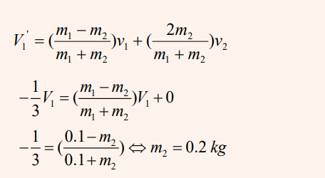
To understand this, use billiards as shown in the previous lesson
Some times after hitting the balls, they do not move in a straight line most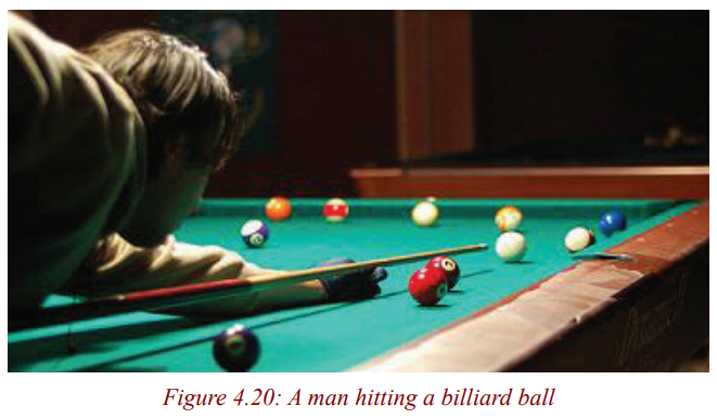
especially (those who know how to play it) when you want to score in the
centre hole. You must make sure that you hit the ball in target so that it movesat a certain angle.
Activity 13
• Try to hit a billiard ball as shown in figure above.
• Observe what happens when one ball hits another.
• Note down your observations.• Present your findings/observation to the whole class.
On Striking the balls ,energy and momentum is conserved.
Conservation of momentum and energy can also be applied to collisions in
two or three dimensions and in this case the vector nature of momentum isimportant.
One common type of non-head-on collision is one for which one particle
(called the “projectile”) strikes a second particle initially at rest (the “tangent”particle). This is the common situation in games such as billiards.
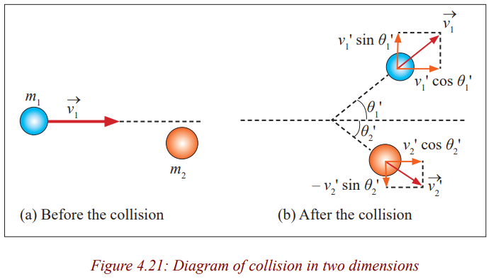
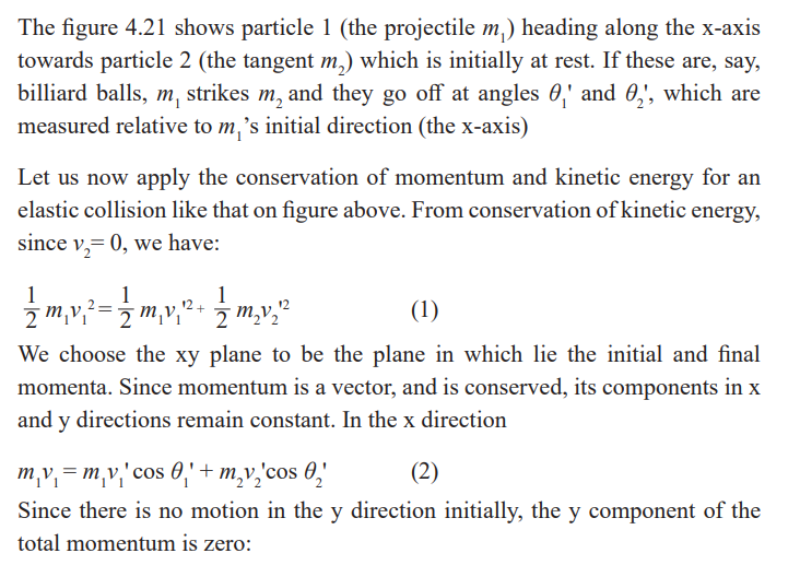
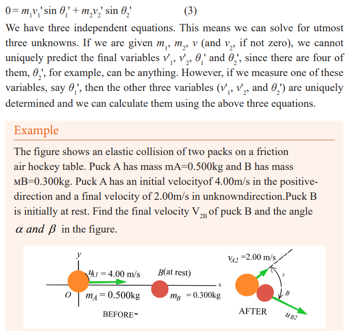
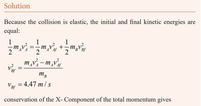
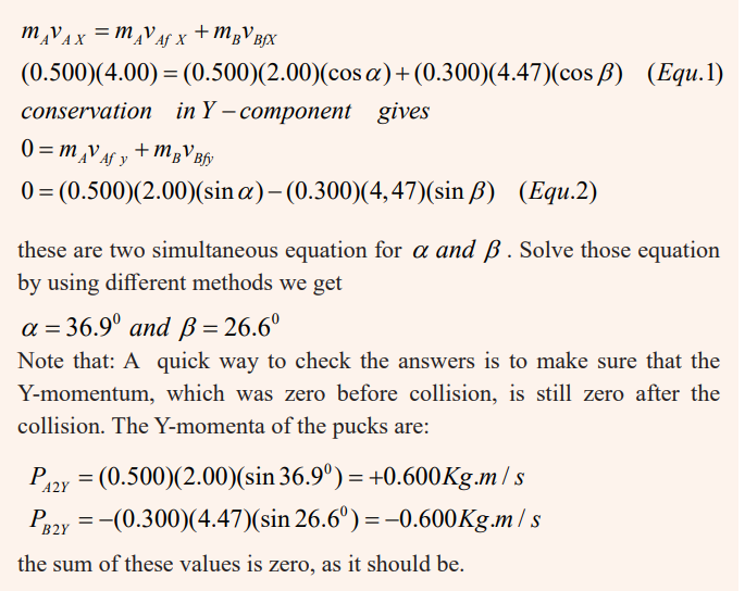
Inelastic collision
Collisions in which kinetic energy is not conserved are called inelastic
collisions. Some of the initial kinetic energy in such collisions is transformedinto other types of energy, such as thermal or potential energy.
A common example of a perfectly inelastic collision is when two objects
collide and then stick together afterwards and move with a common velocityafter colliding.
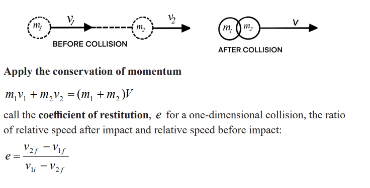
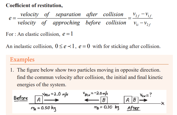
2. An Object A of mass 2 kg is moving with a velocity of 3 m/s and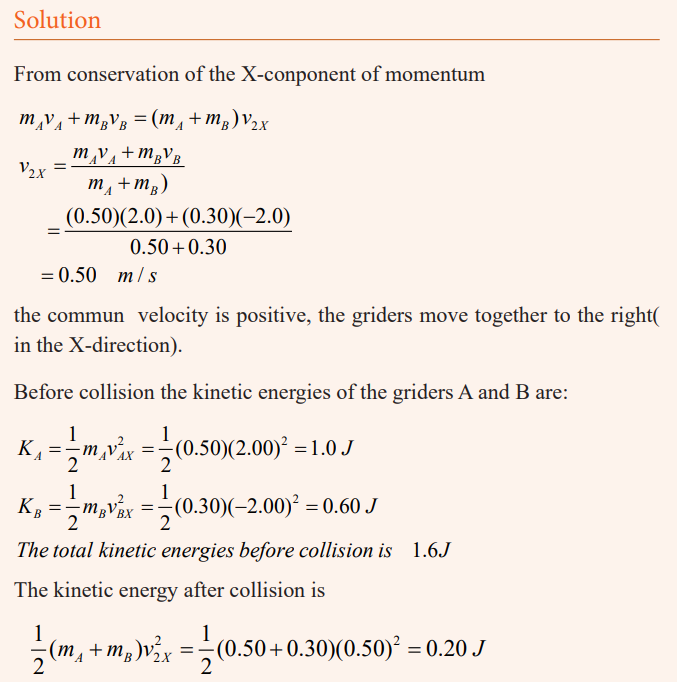
collides head on with an object B of mass 1 kg moving in the opposite
direction with a velocity of 4 m/s. After collision both objects sticks,so that they move with a common velocity v. calculate v.
Solution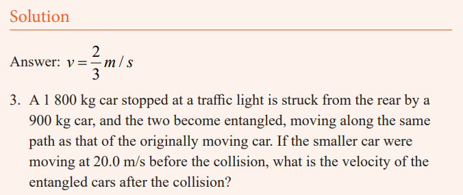
The phrase “become entangled” tell us that this is a perfectly inelastic
collision.Answer: v=6.67m/s
Other examples of collision
The Ballistic Pendulum
1. The ballistic pendulum (seen figure below) is an apparatus used to
measure the speed of a fast-moving projectile, such as a bullet. A
bullet of mass mB is fired into a large block of wood of mass mw
suspended from some light wires and makes a completely inelastic
collision with it. The bullet embeds in the block, and the entire system
swings through a height h. How can we determine the speed of thebullet from a measurement of h??
Solution
Let configuration (A) be the bullet and block before the collision, and
configuration (B) be the bullet and block immediately after colliding.
The bullet and the block form an isolated system, so we can categorize thecollision between them as a conservation of momentum problem.
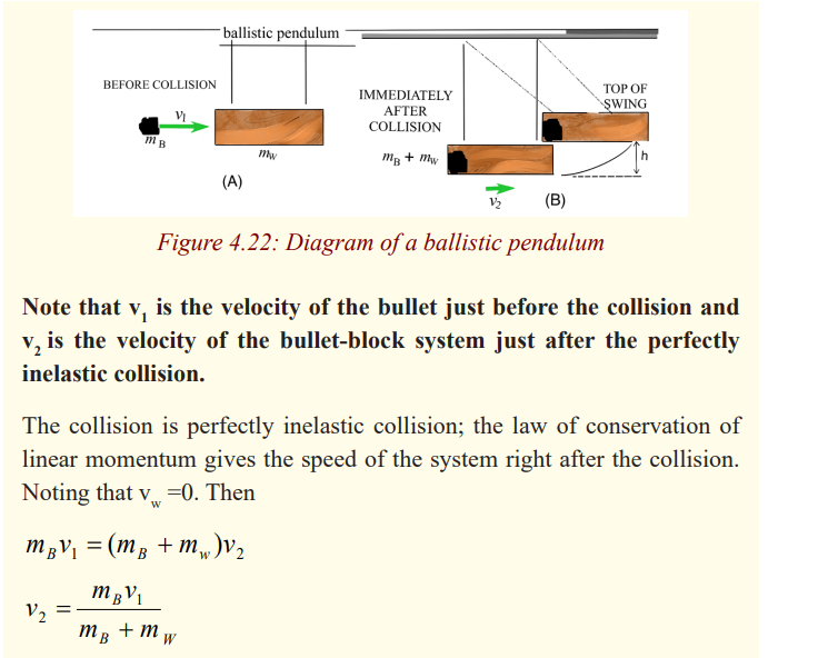
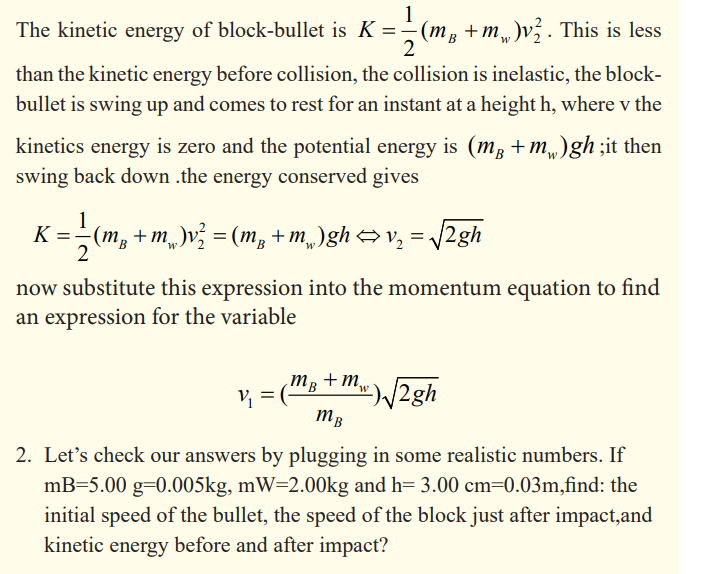
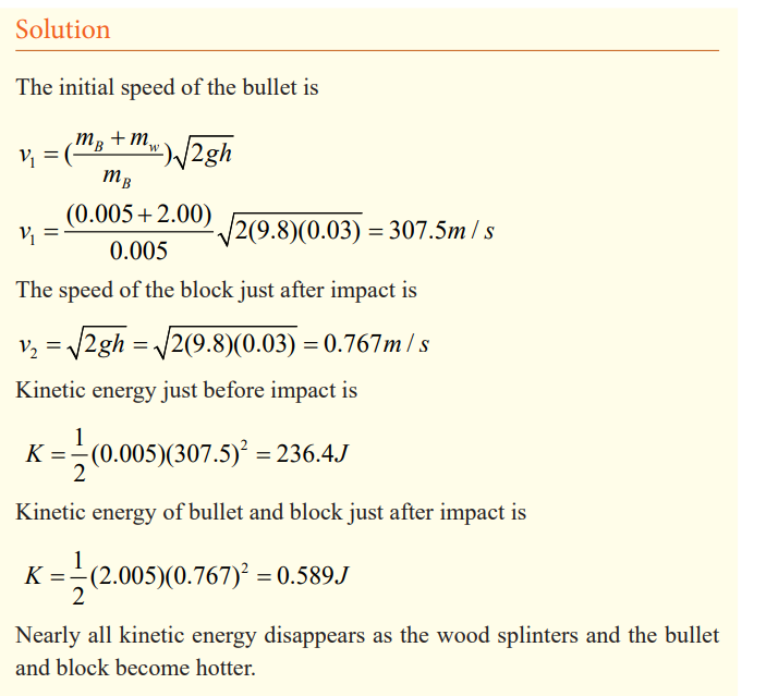
An automobile collision
A 1000Kg compact car is travelling North at 15 m/s when it collides with
a 2000 kg truck travelling East at 10m/s. all occupants are wearing seat
belts are there are no injuries, but the two vehicles are thoroughly tangled
and move away from the impact point as one mass. The insurance adjustor
has asked you to find the velocity of the wreckage just after the impact.What do you tell her? The figure below show the situation
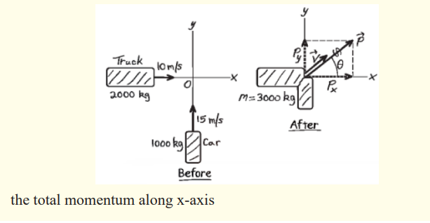
If the velocities of the two objects make a certain angle before collision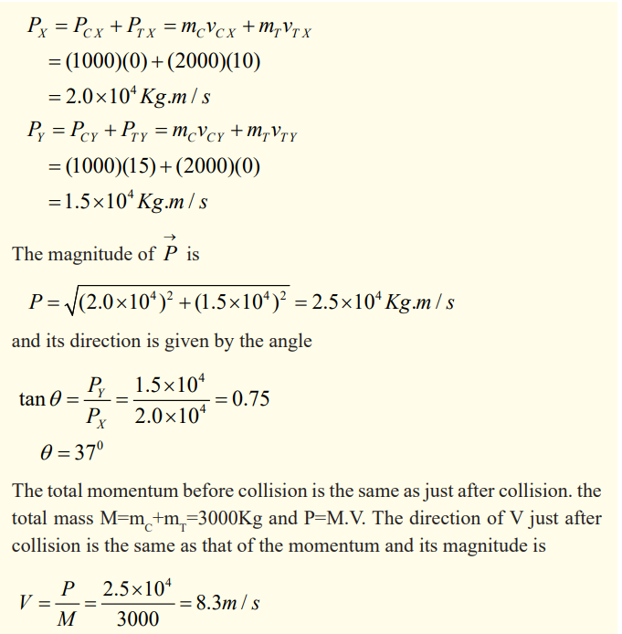
and after collision they stick together, analytically we have this situation:
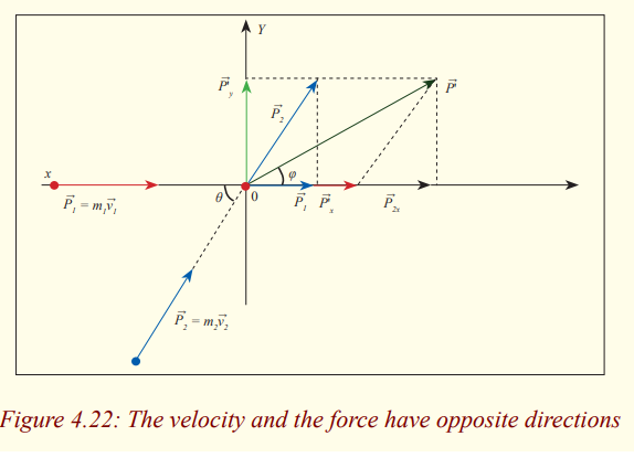
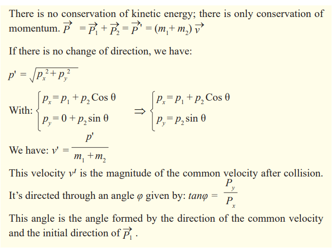
END UNIT ASSESSMENT
“Work, Energy and Power”
1. A worker lifts up a stone of 3.5kg to a height of 1.80m each 30s. Findthe work done in one hour.
2. Calculate the kinetic energy and the velocity required for a 70kg pole
vaulter to pass over a 5.0m high bar. Assume the vaulter’s centre of
mass is initially 0.90m off the ground and reaches its maximum heightat the level of the bar itself.
3. Calculate the power required of a 1400 kg car under the following
circumstances
a) The car climbs a 10° hill at a steady 80km/h and
b) The car accelerates from 90 to 110km/h in 6.0s to pass another
car on a level road. Assume the force of friction on the car is700N in both parts of the problem.
4. A woman of mass 75kg walks up a mountain of height 20m.
a) What is the work done?
b) The walking up being done in 1.5 min, find the power,
c) What time will be taken by this woman to walk up the 20m inorder to develop a power of 73W?

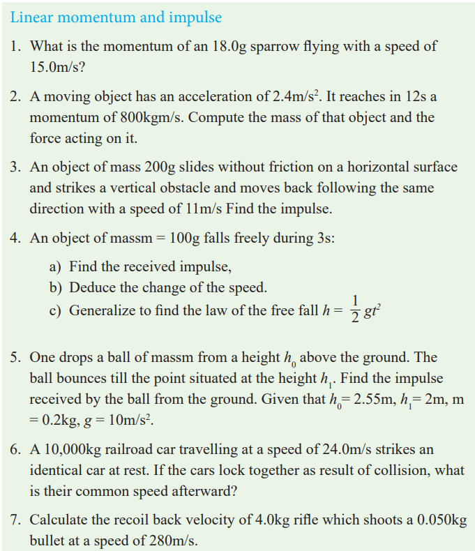
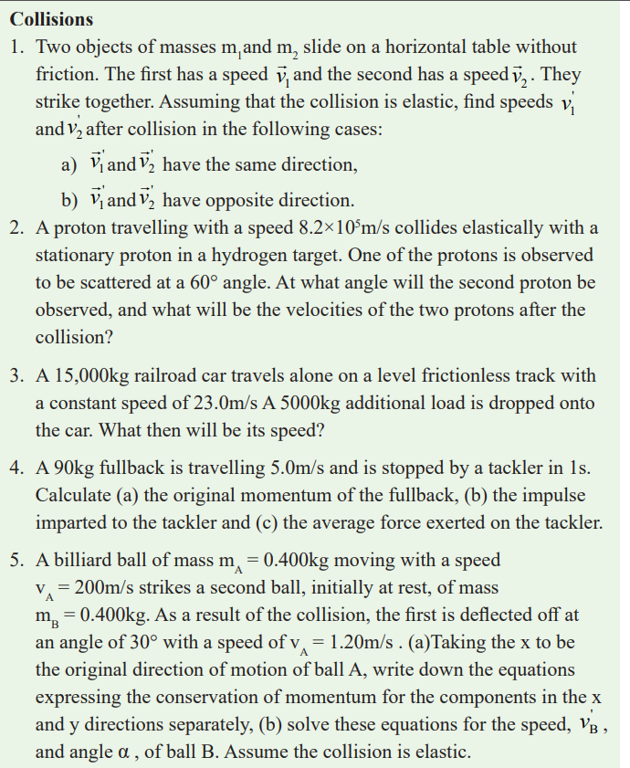
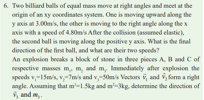
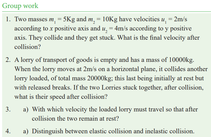
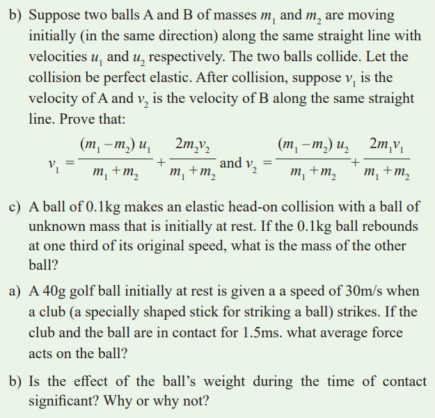
Unit 5 : Kirchhoff ’s Laws and Electric Circuits
Key Unit Competence
Analyse the complex electric circuits using Kirchhoff’s laws
My goals
By the end of this unit, I will be able to:
* analyse complex electric circuits using Kirchhoff’s laws.
* identify sources of electric current.
* describe components of simple electric circuits.
* state Kirchhoff’s laws and apply them to solve problems in electric
circuits.
* acquire practical skills to manipulate apparatus and evaluate
experimental producers.
* explain the differences between the potential difference and
electromotive forces.
Introductory activity
Provided two bulbs, cell holder, bulb holder, voltmeter, ammeter, connecting
wires and a switch.
1. Make a simple electric circuit (as in the above figure) and comment
on your observation
2. On the circuit made in (1), add a voltmeter and an ammeter.
3. What would happen if you remove one bulb from the circuit?
4. Would there be another type of connection of the circuit? Try it and
comment your observation.
5. Discuss on the function of each element in provided list.
Introduction
This unit is one of the most interesting units in Physics. Even if you
ask someone who did not have enough studies in Physics he or she
will tell you that People studying physics will be engineers specifically
electricians. This Unit addresses the principles those electricians use in
their career.
Review of elements of simple electric circuits
and their respective role
An electric current consists of moving electric charges. Electric current must
flow in electric devices connected by conductors (wires). The motion of
electrons in a conductor is compared to water flow in a pipe. To move electrons,
there must be a source of electric current, a cell, a battery, a generator which
acts as a pump of water.
Making a simple circuit
Activity 1
Making a simple electric circuit with a bulb, a battery and wires
Materials:
* 2 pieces of copper wire
* 1 bulb
* 1 battery
Procedure
1. Examine diagrams A-J below. Predict whether the circuit will be
complete, and record your prediction on the chart below.
2. Demonstrate the arrangements to test your predictions..
PREDICTION CHART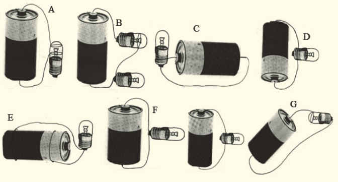
Activity 1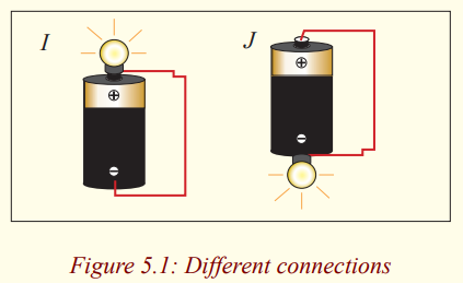
What makes the bulb light?
You may already understand an electrical circuit, or this may seem
like magic to you. Give what your teacher demonstrated some thought.
Why do you think the bulb in the diagram lights?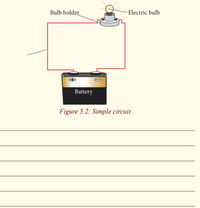
It would be useful here to summarize some basic electricity points which
you may know already.
a) A current flows along a metal or wire when a battery is
connected to it.
b) The current is due to free electrons moving along the metal.
c) The battery has a potential difference p.d or voltage
between its poles due to chemical changes inside thebattery. The p.d. pushes the electrons along the metal.
One pole of the battery is called the positive (+) pole, the other is called the
negative (-) pole. The “conventional” current, shown by an arrow, flows
in a circuit connected from the + to the – pole. The electrons carrying the
current along the circuit wires actually move in the opposite direction to the
conventional current but this need not to be taken in account in calculations
or circuit formulae.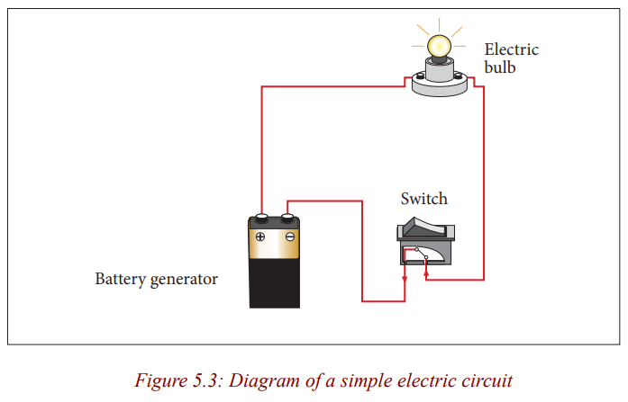
Any path along which electrons can flow is a circuit. For a continuous flow
of electrons, there must be a complete circuit with no gaps. A gap is usually
provided by an electric switch that can be opened or closed to either cut off orallow energy flow.
Most circuits contain more than one device that receives electric energy
from the circuit. These devices are commonly connected in a circuit in one
of two ways, series or parallel. When connected in series, the devices and
wires connecting them form a single pathway for electron flow between the
terminals of the battery, generator or wall socket. When connected in parallel,
the devices and wires connecting them form branches, each of which is aseparate path for the flow of electrons.
Making a series and parallel circuit
Activity 2
Making a series circuit
Materials:
* 1 Battery .
* 3 Bulbs.
* 3 bulb holders .
* Assembled battery holder.* 4 Pieces of copper wire (as needed).
Procedure
1. Construct a complete circuit with a battery and a bulb.
2. Using another wire, add a second bulb as shown on the picturebelow.
3. What did you notice happened to the first bulb when the second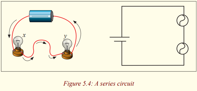
bulb was added?
_____________________________________________________
_____________________________________________________
_____________________________________________________
4. Look carefully at how the series circuit is set up. Write a prediction
of what you think will happen if you unscrew one of the bulbs.
_____________________________________________________
__________________________________________________________________________________________________________
Why did you make this prediction?
_____________________________________________________
__________________________________________________________________________________________________________
5. Unscrew bulb “X”. Describe what happens to bulb “Y”.
_____________________________________________________
__________________________________________________________________________________________________________
6. Tighten bulb “X”, and unscrew bulb “Y”. Describe what happens
to bulb “X”.
_____________________________________________________
__________________________________________________________________________________________________________
7. Add a third bulb to your series circuit. What happens to the brightness
of the bulbs each time another bulb is added to the series?
_____________________________________________________
__________________________________________________________________________________________________________
8. Add a third bulb to your series circuit. What happens to the brightness
of the bulbs each time another bulb is added to the series?
_____________________________________________________
__________________________________________________________________________________________________________
9. Draw a schematic diagram of the circuit you constructed with
three bulbs.
Activity 3
Making a parallel circuit
Materials:
* 1 battery
* 3 bulbs
* Assembled battery holder 3 bulb holders* 6 pieces of copper wire
Procedure
1. Construct a complete circuit with one battery and one bulb.
2. Using another two wires, add a second bulb as shown in the figurebelow.
3. What do you notice happened to the first bulb when the second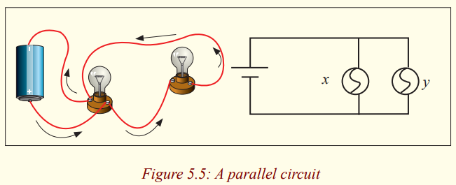
bulb was added?
_____________________________________________________
__________________________________________________________________________________________________________
4. Look carefully at how a parallel circuit is set up. Write a
prediction of what you think will happen if you unscrew one of
the bulbs in the parallel circuit.
_____________________________________________________
__________________________________________________________________________________________________________
Why did you make this prediction?
_____________________________________________________
__________________________________________________________________________________________________________
5. Unscrew bulb “X”. Describe what happens to bulb “Y”.
_____________________________________________________
__________________________________________________________________________________________________________
6. Tighten bulb “X” and unscrew bulb “Y”. Describe what happens
to bulb “X”.
_____________________________________________________
__________________________________________________________________________________________________________
After carrying out experiments for series and parallel circuits,
* What advantages and disadvantages can you note for the two cases?
* What are the characteristics of a series connection and a parallelconnection?
Application activity 5.1
1. If a battery provides a high voltage, it can ____.
a. do a lot of work over the course of its lifetime
b. do a lot of work on each charge it encounters
c. push a lot of charge through a circuit
d. last a long time
2. Which of the following is true about the electrical circuit in your
flashlight?
a) Charge moves around the circuit very fast - nearly as fast as
the speed of light.
b) The battery supplies the charge (electrons) which move
through the wires.
c) The battery supplies the charge (protons) which move through
the wires.
d) The charge becomes used up as it passes through the light
bulb.
e) The battery supplies energy which raises charge from low to
high voltage.f) Nonsense! None of these are true.
series connections of resistors
For a series combination of two resistors, the currents are the same in both
resistors because the amount of charge that passes through R1 must also passthrough R2 and R3 in the same interval of time.
The potential difference at the generators is equal to the sum of potential
difference at each resistor mean that The potential difference applied acrossthe series combination of resistors will divide between the resistors.
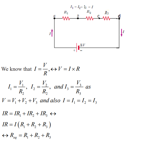
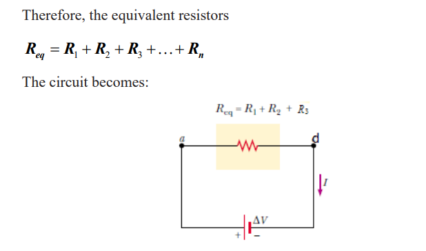
Parallel connection of resistors
The total current equal to the sum of the current pass through the separatebranches.
The potential difference is the same at each resistor and at the generator or
cell.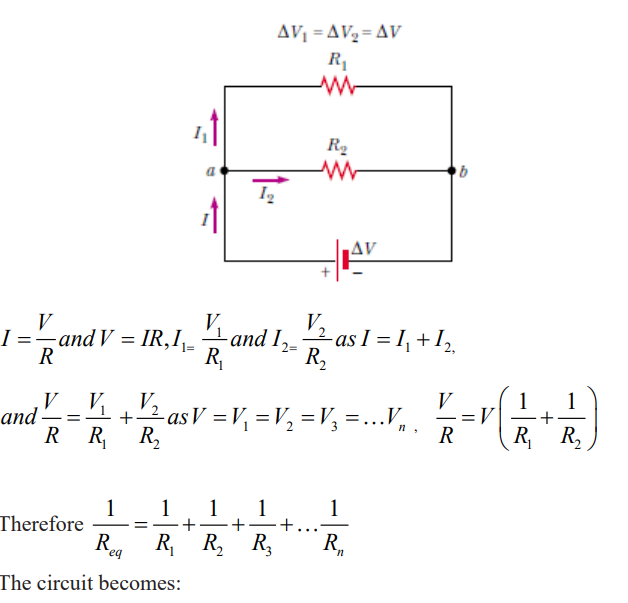
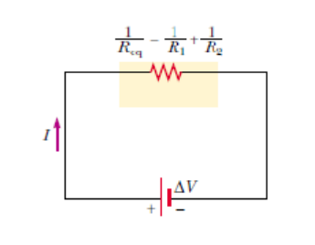
Conclusion
Series and parallel connections each have their own distinctive characteristics.
In a series circuit, the current is the same at all points; it is not used up. In a parallelcircuit the total current equals the sum of the currents in the separate branches.
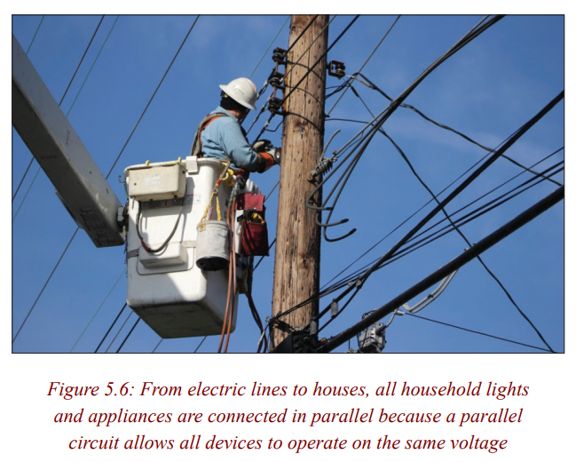
Application activity 5.2
1. As the number of resistors in a series circuit increases, the overall
resistance ______ (increases, decreases, remains the same)
and the current in the circuit _______ (increases, decreases,
remains the same).+
2. Three resistors are connected in series. If placed in a circuit with
a 12 V power supply. Determine the equivalent resistance, the
total circuit current, and the voltage drop across and current at
each resistor.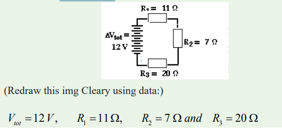
3. Determine the values of the current at and electric potential differenceacross each of the resistors in a parallel circuit.
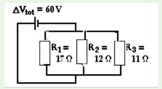
Generators and receptors
Electromotive force
Activity 4Electromotive force of a generator
Materials
* Battery of 6V,
* Rheostat
* Voltmeter
* Ammeter* Connecting wires
Procedure1. Make the connection as shown in the following figure.
2. Write down the voltage and the current indicated by the voltmeter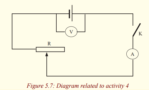
and the ammeter when the switch is open.
3. Close the switch and vary the current in the circuit by varying the
values of the rheostat and every time write down values of voltageand current indicated respectively by voltmeter and Ammeter.
4. Fill in the following table the obtained data:
5. When you vary the value of the resistance of the rheostat, does the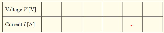
intensity of current remain constant? Why?
6. Does the voltage remain constant?
7. What is the maximum voltage that you have got? How is thisvoltage called?
8. In general, if a charge Q (in coulombs) passes through a source of
emf E (in volts) which relation will give the electrical energy Wsupplied by the source (in joules)?
9. Which relation will give the total power of the source?Interpretation
A voltmeter connected to terminals of a battery measures the voltage between
terminals of battery. When the switch was closed, we have noticed that therewas a current across the circuit and the value of the voltage has been changed.
By varying the value of the resistance of the rheostat, current in the circuit is
changed; voltage indicated by the voltmeter changes also, it decreases when
current increases. Its maximum value is reached when the switch is open.Such voltage is called electromotive force E (emf) of the battery.
The electromotive force emf E of a source (a battery, generator, etc) is the
energy transferred to electrical energy when unit charge passes through it.
In other words, we can say that the emf of a source of electrical energy is itsterminal p.d. on open circuit.
The emf of a battery is the maximum possible voltage that the battery canprovide between its terminals.
Internal resistance
Activity 5
Existence of internal resistance in a generator
* Consider a certain number of cells which you put in an electricapparatus, like a radio…
* With your cheek, feel their temperatures before use.
* Put the cells in your apparatus and let them work for a certain time.
* Remove the cells and again with your cheek, feel the newtemperature of the cells then answer the following questions:
• Are the two temperatures of the cells equal? (Before and after
use)
• If not, what do you think is the cause of different temperatures?
• Is one part of the current produced by the generator consumed byit? Why?
* The same observations can be made by feeling the temperature of
the battery of a telephone before a call and after a call of about 10
minutes. Have you felt the increasing of temperature of a phone afterusing it? If yes, you think it’s due to what?
The term internal resistance refers to the resistance within an emf. The terminal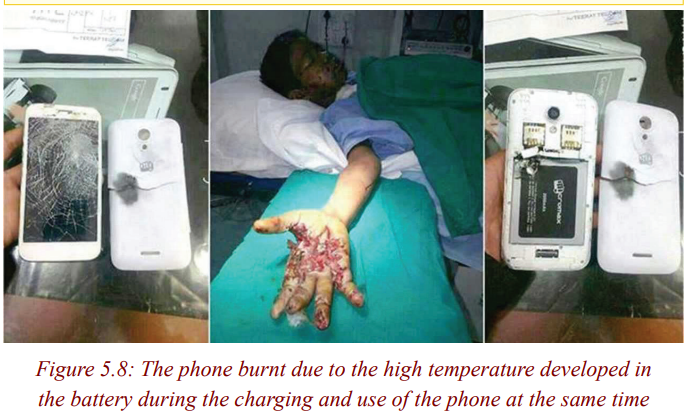
p.d. of a cell on closed circuit is also the p.d. applied to the external circuit.
In an external circuit electrical energy is changed onto other forms of energy
and we regard the terminal p.d. of a cell on closed circuit as being the numberof joules of electrical energy changed by each coulomb in the external circuit.
Not all the electrical energy supplied by a cell to each coulomb is changed
in the external circuit. The “lost” energy per coulomb is due to the cell itself
having resistance. Each coulomb has to “waste” some energy to get through
the cell itself and so less is available for the external circuit. The resistance of
a cell is called its internal resistance [r] and depends among other things onits size.
The electric power dissipated as heat in a cell is given by: Pi = I2 r
Examples
1. The power dissipated as heat in a cell is of 7W, find its internal
resistance if a current of 2A flows through it.
2. Find the power dissipated as heat in a generator of internalresistance 0.6Ω crossed by a current of 3A.
Solution
Remark: Any electrical generator, then, has two important properties,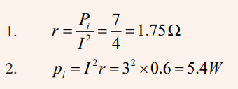
an emf E and an internal resistance r. E and r may be
represented separately in a diagram, though in practice they
are together between the terminals. To represent a cell, we
can write (E, r). So we can think of the battery as an “electric
pump”, with its emf E pushing the current round the circuit
through both the external (outside) resistor R and internalresistance r
In an electric circuit, a generator is then represented by the following symbol:
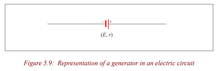
Activity 6
Experiment to find the emf (E) and the internal resistance (r) of acell
Materials
* 1.5V (approx) cell,
* Resistance box,
* Push switch,* Digital Ammeter (0-1A).
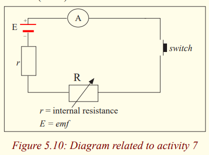
Relationship between the P.d and the emf at terminals of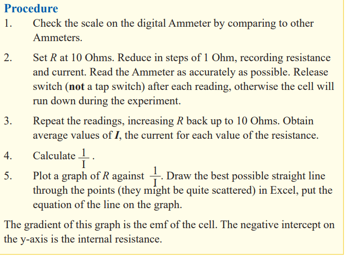
a cell of a closed circuit
Activity 7
Relation between the Emf and the P.d
Materials
* Dry cell,
* Analogy multimetres (2),* Rheostat and switch.
Procedure1. Set up the circuit as shown.
2. Set the resistance of the rheostat to a large value to protect the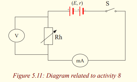
circuit before switch on the circuit.
3. Set the milliammeter to the range 0-1 A or suitable range.
4. Set the voltmeter to the range 0-5V or suitable range.
5. Switch on the circuit. Record down the readings of the Ammeter
and voltmeter. Slide the rider of the rheostat to another position.
Record the readings of the ammeter and voltmeter again. Tabulatethe results.
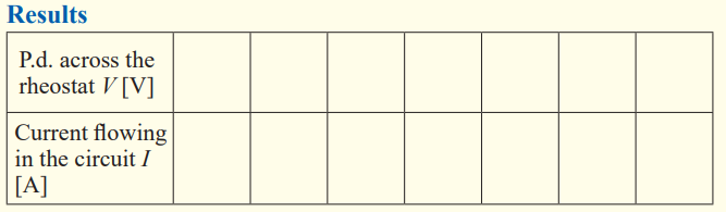
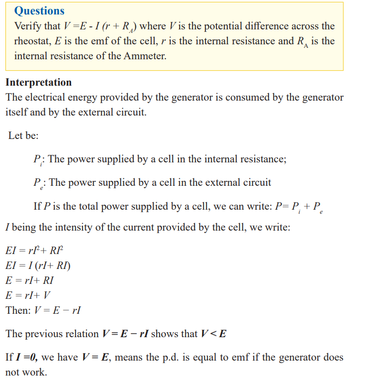
Examples
1. What is the voltage at terminals of a battery of emf 3V and internal
resistance 0.3 Ω when sending a current of 1.5 A in a circuit?
2. Knowing that the voltage at terminals of a cell is 1.5V and the
current crossing the circuit is 1.2 A. Find its emf if its internalresistance is of 0.4 Ω.
Solution
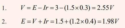
Efficiency of a cell
Activity 8
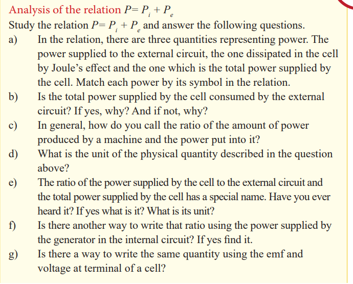
Since the relation above involves the total power in the circuit, which is the
sum of the power supplied in the external circuit and the power dissipated in
the cell itself, this one is useful. It’s used to find the efficiency of the cell andhow to calculate the voltage at terminals of a cell or battery.
To calculate the efficiency of the cell.
Ohm’s law for a circuit having a cell and a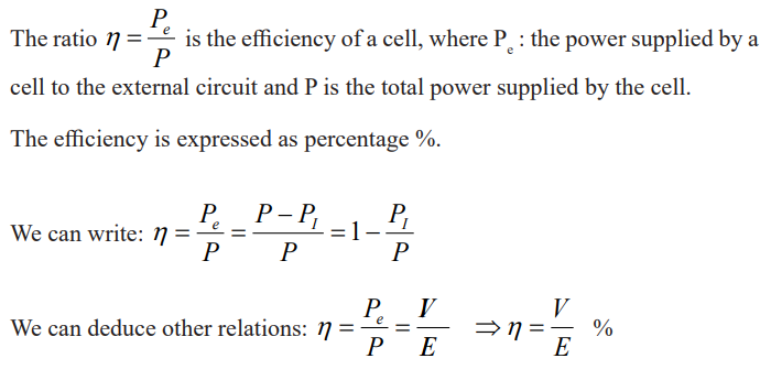
resistor
Activity 9
From the observation of the following diagram and analysingdifferent elements deduce a relation
Questions:
a) State the Ohm’s law.b) Observe the following diagram and list constituting elements.
c) Do these elements make an electric circuit? If yes, why?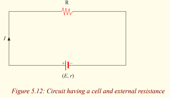
d) Are these elements connected in series or in parallel? Why?
e) How can you find the total resistance of a series connection?
f) Having the total power supplied by a cell, the power supplied by a
cell in an external circuit and the power distributed by the internal
resistance. Write the relation between them.
g) Write down relations for each type of power and substitute them
in the relation above. (Powers dissipated in internal and external
resistances must be written in terms of resistance)
h) From the relation found, deduce the emf E. The relation found
expresses the Ohm’s law for a circuit having a cell and a resistor.i) Express the intensity of the current for this specific case.
Pouillet’s law
We can obtain a form of Ohm’s law by considering a segment of straight
wire of uniform cross-sectional area A and length , as shown in Figure 5.8.
A potential difference is maintained across the wire, creating in the wire anelectric field and a current.
The equation representing the dependency of the resistance (R) of a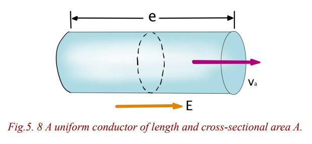
cylindrically shaped conductor (e.g., a wire) upon the variables which affectit, is called Pouillet’s law,
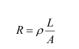
where
• L represents the length of the wire (in m). The longer the wire, the more
resistance that there will be
• A represents the cross-sectional area of the wire (in m2). The wider the wire,
the less resistance that there will be to the flow of electric charge. When all
other variables are the same, charge will flow at higher rates through wider
wires with greater cross-sectional areas than through thinner wires.
•represents the resistivity of the material (in ). Some materials are better
conductors than others and offer less resistance to the flow of charge; they
are better conductors. Silver is one of the best conductors but is never used
in wires of household circuits due to its cost. Copper and aluminum are
among the least expensive materials with suitable conducting ability to
permit their use in wires of household circuits.
Resistivity of a material is numerically the resistance of a sample of unit
length and unit cross-section area, at a certain temperature. The resistivity
of a material is dependent upon the material's electronic structure and its
temperature. For most (but not all) materials, resistivity increases withincreasing temperature.
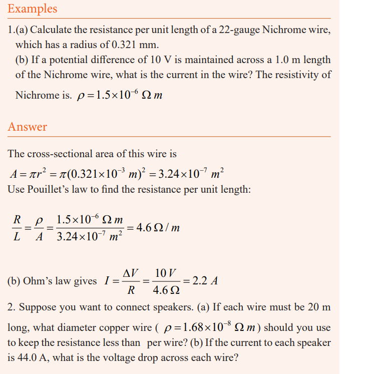
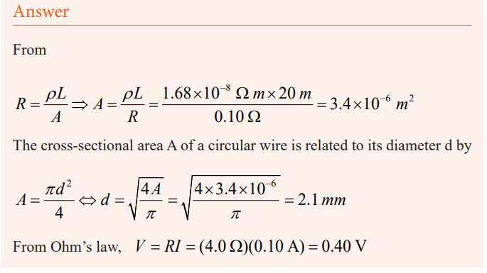
Application activity 5.3
1. The total power of a battery is of 9V and its internal resistance 3Ω.
Knowing that the current crossed is of 0.4A. Find the efficiency of
the battery.
2. A generator of internal resistance 2Ω sends a current of 4A in a
resistor of resistance 10Ω. Calculate its power.
3. An external resistance of 4Ω is connected to an electric cell of
emf 1.5V and internal resistance 2Ω. Calculate the intensity of the
current flowing the external resistance.
4. An electric cell of emf 1.5V and internal resistance 2Ω is
connected in series with a resistance of 28Ω. Calculate the power
dissipated as heat in the cell.Combination of cells
Activity 10
Cells wired in parallel and in series
Materials:
* 3 batteries
* 2 bulbs
* 3 assembled battery holders
* 2 bulb holders
* 6 pieces of copper wireProcedure
1. Construct a complete circuit with one battery and one bulb.
2. Observe the brightness of the bulb.
3. Construct the circuit below. Are these batteries in series or parallel?
_____________________________________________________
__________________________________________________________________________________________________________
How can you tell?
_____________________________________________________
__________________________________________________________________________________________________________
4. Observe the brightness of this bulb. Is the bulb brighter than it was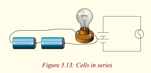
with one battery?
_____________________________________________________
__________________________________________________________________________________________________________
5. If you added a third battery to this circuit in series, what do you
think would happen to the brightness of the bulb?
_____________________________________________________
__________________________________________________________________________________________________________
Why do you think this?
_____________________________________________________
__________________________________________________________________________________________________________
6. Add a third battery to this circuit. Describe what happens to the bulb
as this battery is added to this circuit in series and why you think the
bulb is acting in this way.
_____________________________________________________
__________________________________________________________________________________________________________
7. Construct another complete circuit with one battery and one
bulb. Record again what the brightness of the bulb is using yourbrightness metre.
8. Look at the pictures below, are the batteries in the picture in series
or parallel?
_____________________________________________________
__________________________________________________________________________________________________________
How can you tell?
_____________________________________________________
__________________________________________________________________________________________________________
Construct the circuit in 8. Is the bulb brighter with two batteries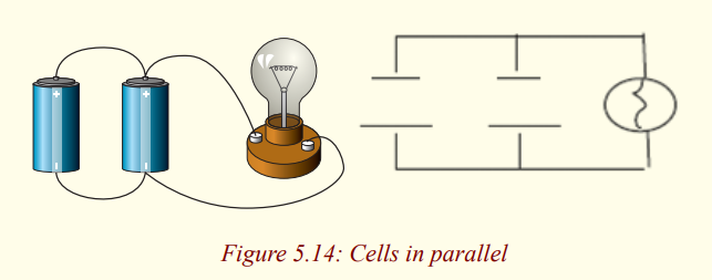
than it was with one battery?
_____________________________________________________
__________________________________________________________________________________________________________
9. Add one more battery to this circuit in parallel. Describe what
happens to the bulb as one more battery is added to this circuit in
parallel and why you think the bulb is acting this way.
_____________________________________________________
__________________________________________________________________________________________________________
10. Connect then two batteries in opposition to mean the positive
(negative) terminals of batteries are connected together and the
two free negative (positive) terminals are connected to the bulb.
What happens to the bulb?
_____________________________________________________
__________________________________________________________________________________________________________
11. Connect two batteries in series in opposition with one battery.
When the two free ends of the combination are connected to
terminals of the bulb, what happens to the brightness of the bulb?
_____________________________________________________
__________________________________________________________________________________________________________
Interpretation
Combination in series
When two or more cells are arranged in series, the total emf is the algebraic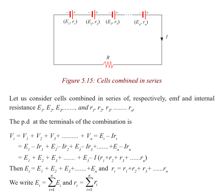
sum of their emfs and the total internal resistance is the algebraic sum of theirinternal resistances
Note: A series arrangement is used to increase the voltage, also the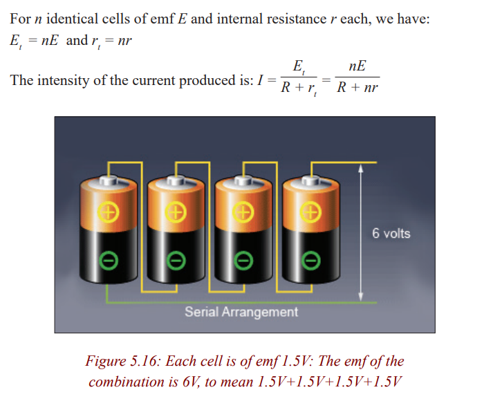
total internal resistance of the circuit, so the energy loss due tointernal resistance is greater than for a single cell.
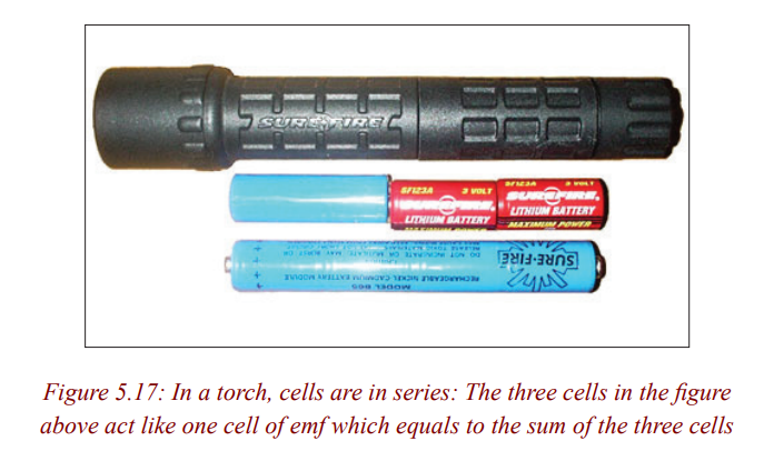
Examples
1. Four 1.5V cells are connected in series to a 12Ω lightbulb. If the
resulting current is 0.45A, what is the internal resistance of eachcell, assuming they are identical and neglecting wires?
2. A certain number of cells of emf 1.5V and internal resistance
2Ω are connected in series. When connected this combination to
an external resistance of 10Ω, a current of 500mA flows in thisresistance. Find the number of cells used.
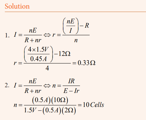
Combination in opposition
Let us see also what the result could be if the cells were associated in opposition
Let us combine two cells in opposition. Two terminals of same sign are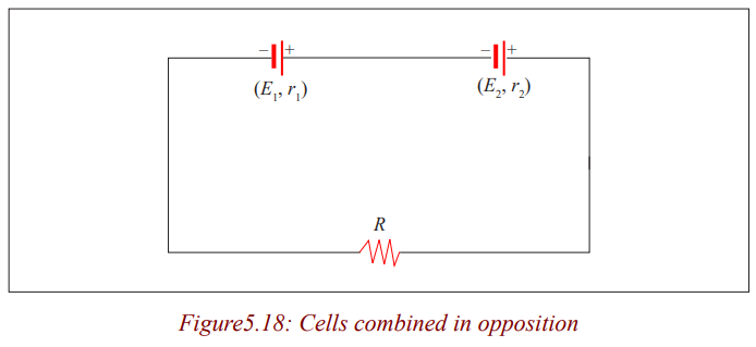
connected together. The direction of the current in the circuit will be determined
by the direction of the current produced by the cell having the higher emf. Forinternal resistances they are in series. So we write:
Note: You might think that connecting batteries in opposition would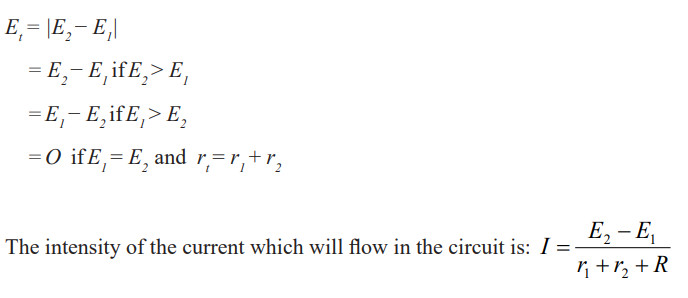
be wasteful. For more purposes, that will be true. But such
an opposition arrangement is precisely how a battery chargerworks.
Example
A cell of emf 2V and internal resistance 0.2Ω is associated in opposition
with another cell of emf 1.5V and internal resistance 1.2Ω. Calculate theintensity of the current knowing that the external resistance is 1.1Ω.
Solution
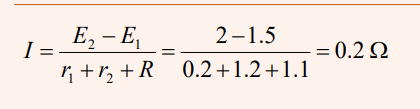
Combination in parallel
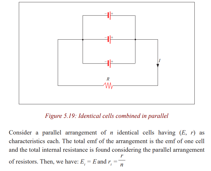
Note: The parallel arrangement is useful normally only if the emfs are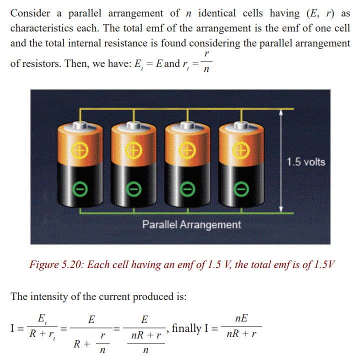
the same. A parallel arrangement is not used to increase the
voltage, but rather to provide large currents. Each of the cells
in parallel has to produce only a fraction of the total current,
so the energy loss due to internal resistance is less than for asingle cell; the batteries will be exhausted less quickly.
Examples
1. We have 8 cells of emf 1.5V and internal resistance 2Ω. Calculate
the intensity of the current flowing in an external resistance of 1Ωconnected to the terminals of the 8 cells combined in parallel.
2. Six cells of unknown emf and internal resistance of 2Ω are
associated in parallel. When an external resistance of 1Ω is
connected to this combination a current of 1.5A is produced.Calculate the emf.
Solution
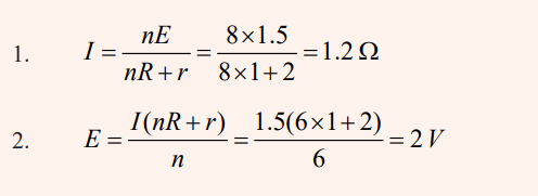
Mixing series and parallel combinations
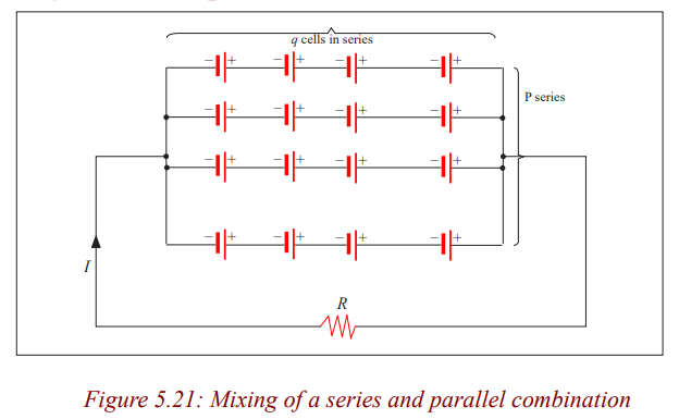
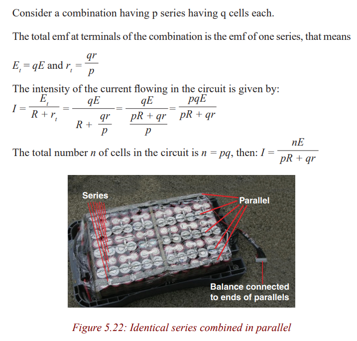
Example
Four cells of emf 4.5V each and internal resistance 2Ω are combined in
series. The combination is connected to an external resistance of 24Ω
a) What is the intensity of the current?
b) Same question if the cells are combined in parallel.
c) Same question if the combination has two parallel series of twocells each.
Solution
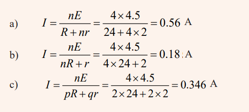
Receptors
Activity 11
Distinguishing a receptor from a passive resistor
a) Observe the following devices and name them
b) What is the use of each one?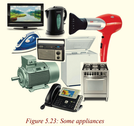
c) The flowing of the current in them produces the same
effect? Explain.
d) Among them, which ones transform the whole electric
energy consumed in heat and which ones transform a part of
electric energy consumed in another kind of energy which is
not heat?
e) As we had in the case of generators, what are characteristicsof these apparatuses?
Conclusion: Among the apparatuses above, there are some which transform
the total electric energy consumed into heat and some transform just a part
into heat, other part transformed into another type of energy which is not heat.
Those which transform the whole quantity of electric energy consumed into
heat are passive resistors or passive receptors and those transforming a part of
the consumed electric energy in another form of energy which is not heat arecalled receptors or active receptors.
The main characteristics are back electromotive force and internal resistance.
Back electromotive force
Back electromotive force (emf) is normally used to refer to the voltage that
is developed in electric motors. This is due to the relative motion between the
magnetic field from the motor's field windings and the armature of the motor!
Internal resistance
The internal resistance of a receptor r’ is its ability to oppose electric current.
When a receptor is traversed by an electric current, part of the energy consumed
is transformed into heat. The power dissipated in the receptor by joule effect
is: PJ = I 2rThe p.d at terminals of a receptor
Activity 12
Find the P.d at terminals of a motor
Materials
* Electric motor
* Ammeter
* Voltmeter* Power supply
Procedure1. Make the connection as shown in the figure below.
Measure the voltage (V) between terminals of the motor (M) and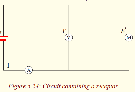
the current I in the circuit.
Questions
a) What is the net electrical power received by the motor?
b) What becomes this power and how is it transformed?
c) What is the relation between the voltage and the back
electromotive force?
d) From the relation found, how do you calculate the intensityof the current flowing?
Application activity 5.4
1. A circuit has in series a generator of emf 6V and internal
resistance 0.1Ω, a receptor of back emf 1.5V and internal
resistance 0.4Ω and a passive resistor of 8.5Ω. Calculate:
a) The intensity of the current flowing in the circuit.
b) The power supply by the generator.c) The quantity of heat produced in the resistor in one minute.
2. A battery has an emf of 12.0V and an internal resistance of 0.05Ω.
Its terminals are connected to a load resistance of 3.00Ω. (a) Find
the current in the circuit and the terminal voltage of the battery.
(b) Calculate the power delivered to the load resistor, the power
delivered to the internal resistance of the battery, and the powerdelivered by the battery.
3. Calculate the terminal voltage for a battery with an internal
resistance of 0.9Ω and an emf of 8.5V when the battery is connectedin series with (a) an 81Ω resistor, and (b) 810Ω.
4. A 9V battery whose internal resistance r is 0.5Ω is connected inthe circuit shown in the figure.
a) How much current is drawn from the source?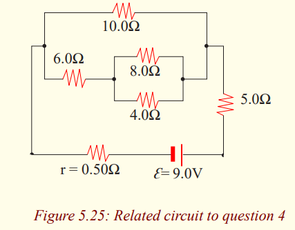
b) What is the terminal voltage of the battery?c) What is the current in the 6Ω resistor?
5. What is the internal resistance of a 12V car battery whose terminal
voltage drops to 8.4V when the starter draws 75A? What is theresistance of the starter?
6. A 1.5V dry cell can be tested by connecting it to a low-resistance
Ammeter. It should be able to supply atleast 22A. What is the
internal resistance of the cell in this case, assuming it is muchgreater than that of the Ammeter?
7. A cell whose terminals are connected to a wire in nickel silver of
resistivity 30 x 10 -6 Ωcm and cross sectional area 0.25mm2
and
length 5m sends a current of 160mA. When the length is reduced
to a half, the intensity of the current is of 300mA. Calculate:
a) The internal resistance.b) The emf of the cell.
8. A cell (E = 1.5V, r = 1.3Ω) sends a current in an external
resistance of 3Ω. Calculate:
a) The intensity of the current in the circuit.
b) The p.d at terminals of the cell.
c) The power of generator.d) The efficiency of the cell.
9. A battery is composed by 120 cells in series. Each element has an
emf of 2V and an internal resistance of 0.001Ω. The combination
is connected to an external resistance of 4.8Ω. Calculate:
a) The intensity of the current in the circuit.
b) The voltage at terminals of the battery.
c) The energy dissipated by joule effect when the currentflows in the circuit in one hour.
Kirchhoff’s rules
Activity 13
Find the equivalent Resistance
In this experiment you will be using a digital multimeter (DMM) which
can function as either a voltmeter or an Ammeter.
The voltmeter must always be wired in parallel with the resistor whose
voltage you are measuring. The ammeter, used to measure current, must
always be wired in series. Disconnect the meter from the circuit before
you change the function setting. Failure to follow these procedures can
result in serious damage to the meter. Be sure that you use the correct unitswith your data.
Materials
* 1 multimeter.
* 1 330 Ω or 240 Ω resistor.
* 1 1000 Ω (1KΩ) resistor.
* 1 2000 Ω (2KΩ) resistor.
* 1 3000 Ω (3KΩ) resistor or 1 3300 Ω (3.3KΩ) resistor.
* 1 0- 10K resistor substitution box.
* 2 spade lugs.
* 2 2’ red banana wires.
* 2 2’ black banana wires.* 4 4” black banana wires.
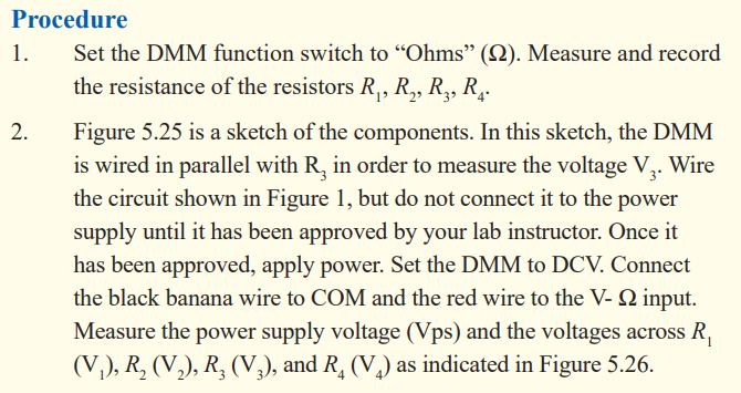
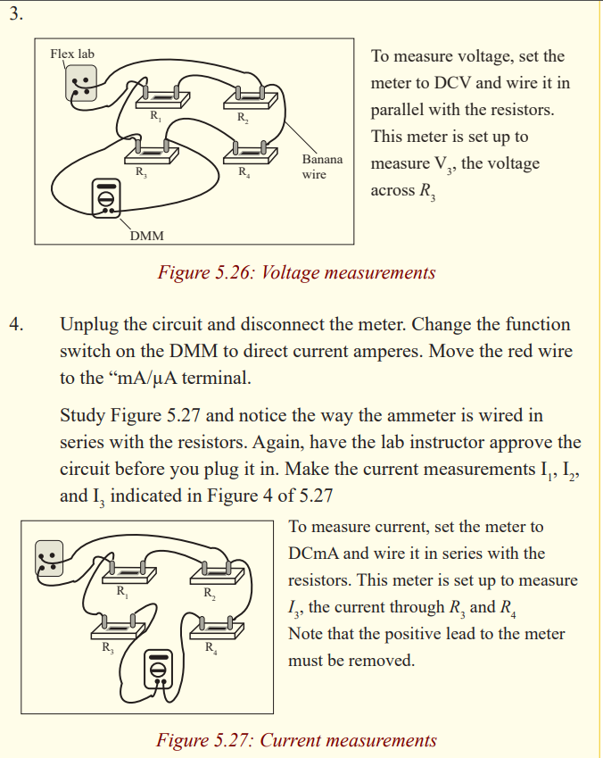
Simple circuits can be analysed using the expression V = IR and the rules
for series and parallel combinations of resistors. Very often, however, it is
not possible to reduce a circuit to a single loop. The procedure for analysing
more complex circuits is greatly simplified if we use two principles calledKirchhoff's rules:
Kirchhoff’s second rule follows from the law of conservation of energy. Let us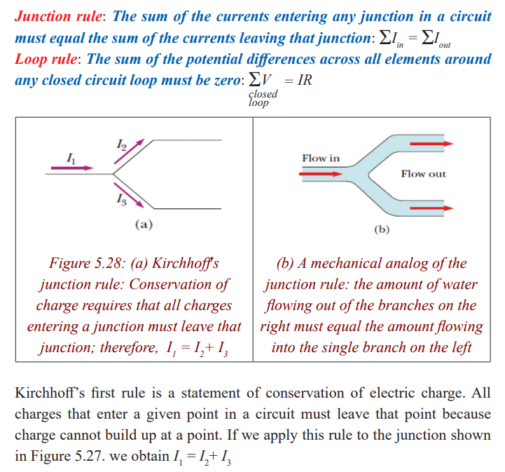
imagine moving a charge around a closed loop of a circuit. When the charge
returns to the starting point, the charge–circuit system must have the same
total energy as it had before the charge was moved. The sum of the increases in
energy as the charge passes through some circuit elements must equal the sum
of the decreases in energy as it passes through other elements. The potential
energy decreases whenever the charge moves through a potential drop -IR
across a resistor or whenever it moves in the reverse direction through a source
of emf. The potential energy increases whenever the charge passes through abattery from the negative terminal to the positive terminal.
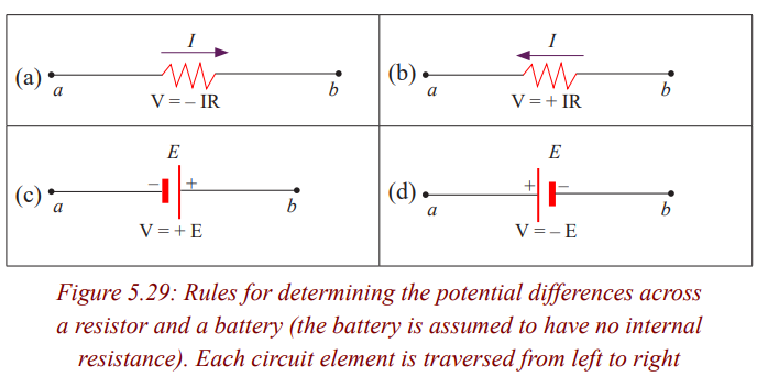
Examples
1. A single-loop circuit contains two resistors and two batteries, as
shown in figure 5.29 (neglect the internal resistances of the batteries).
(a) Find the current in the circuit. (b) What power is delivered toeach resistor? What power is delivered by the 12V battery?

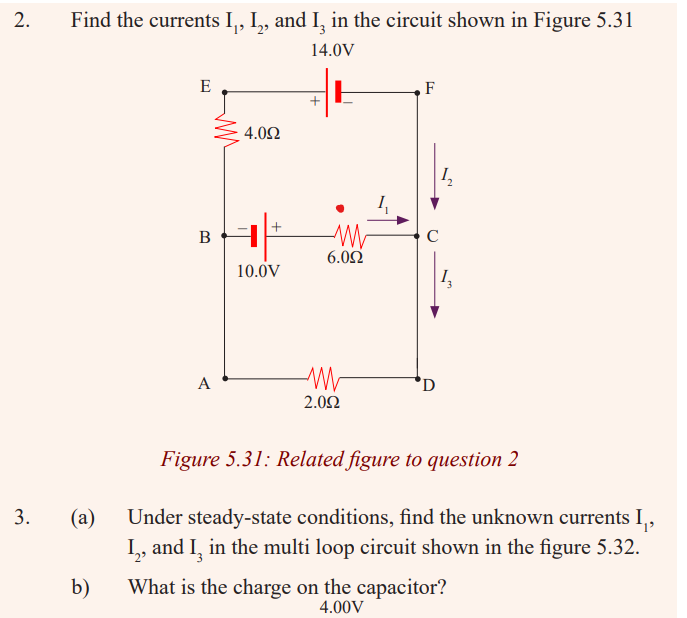
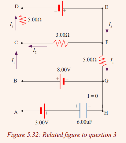
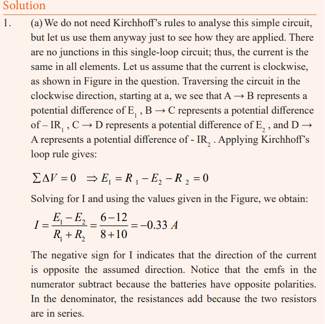
We therefore need only two loop equations to determine the unknown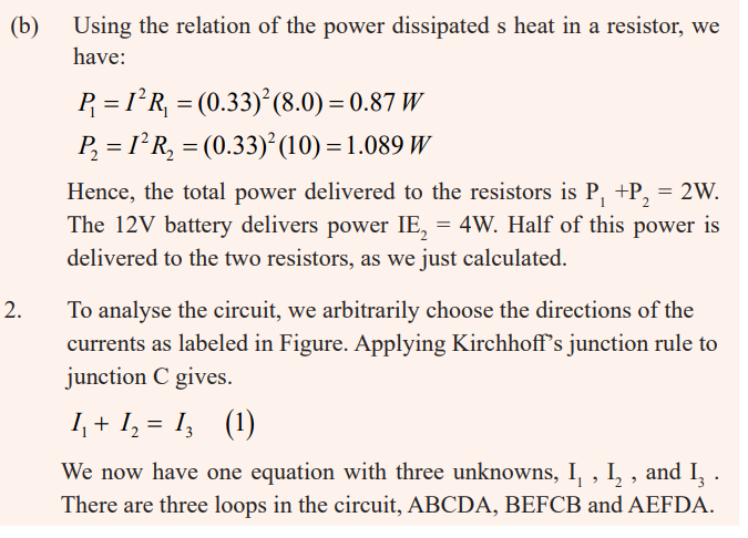
currents. (The third loop equation would give no new information).
Applying Kirchhoff’s loop rule to loops ABCDA and BEFCB andtraversing these loops clockwise, we obtain the expressions
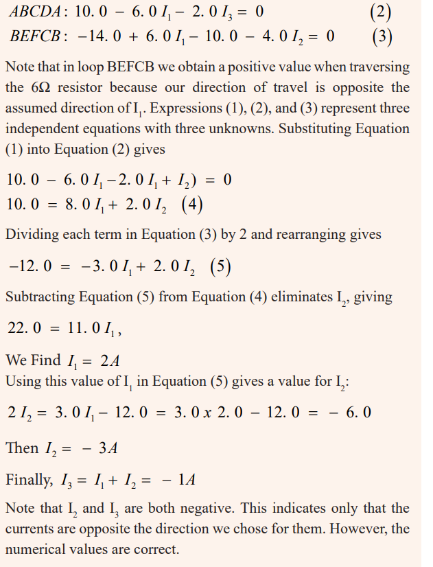
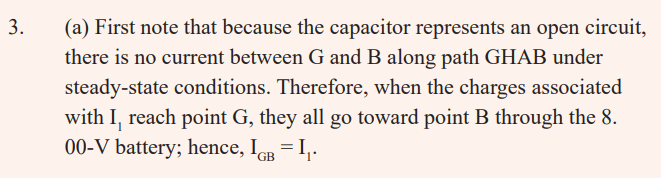
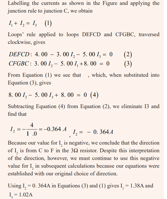
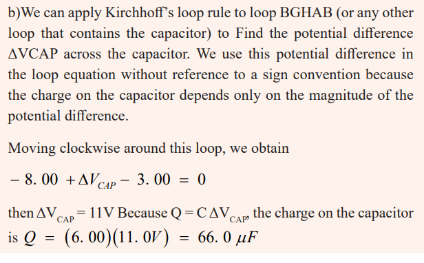
END UNIT ASSESSMENT
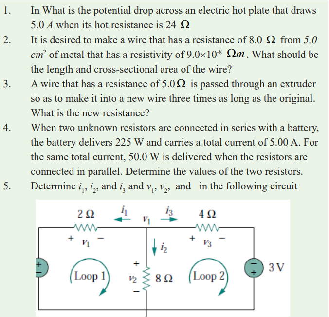
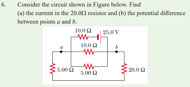
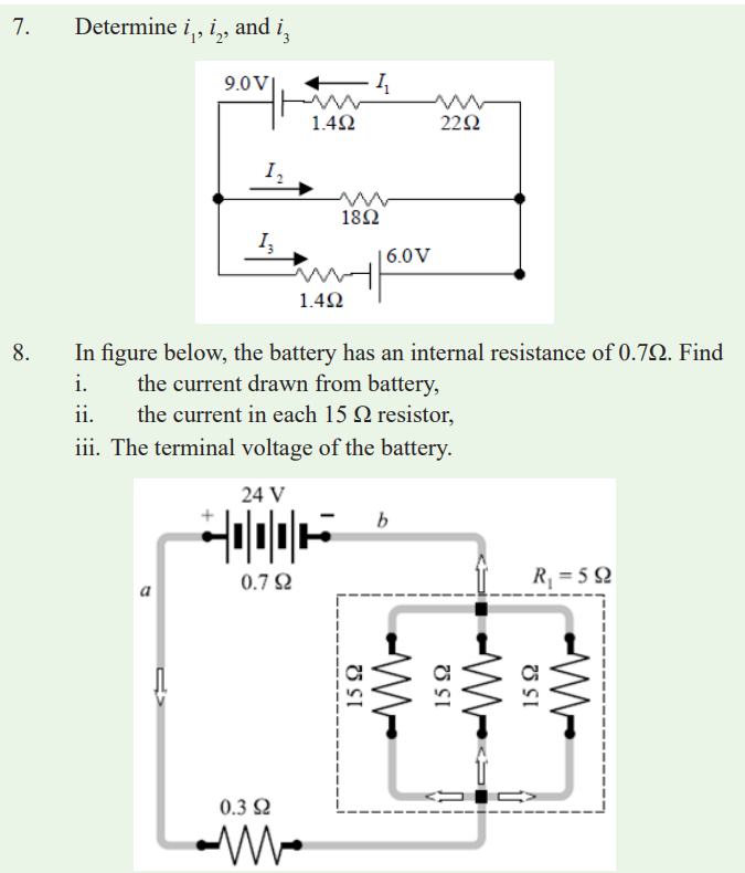
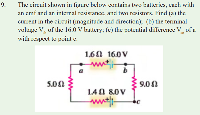
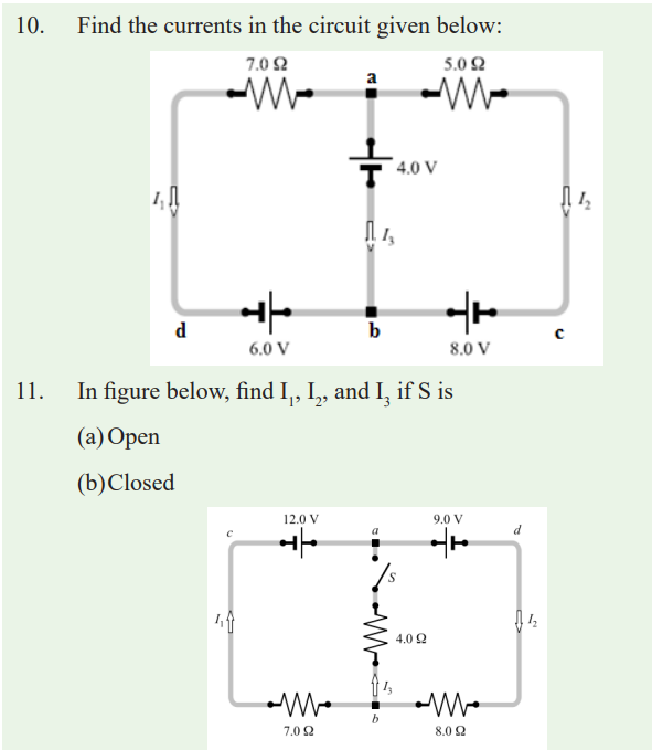
13. A dead battery is charged by connecting it to the live battery of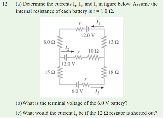
another car with jumper cables as shown in the figure. Determinethe current in the starter and in the dead battery.
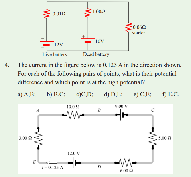
Unit 6 : Sources of Energy in the World
Key unit Competence
Evaluate the energy sources in the world
My goals
By the end of this unit, I will be able:
* identify sources of energy in Rwanda.
* outline the basic features of renewable and non renewable energy
sources.
* evaluate energy uses and availability in Rwanda.
* identify various advantages and disadvantages of various energy
sources.* be aware of the moral and ethical uses associated with use of energy.
Introductory activity
At hospital, during patient treatment, doctors recommend to patients to take
a balanced diet. That is true because as a patient takes medicines and eatvery well, it yields a quick recovery and one gets strong.
Questions:
1.What do you think is contained in food that we eat?
2.Discuss why it is very important to take a sunbath when a person is sick?3.Discuss other different sources of energy in environment?
Introduction
Origins of the power used for transportation, for heat and light in dwelling
and working areas, and for the manufacture of goods of all kinds, among other
applications. The development of science and civilization is closely linked
to the availability of energy in useful forms. Modern society consumes vast
amounts of energy in all forms: light, heat, electrical, mechanical, chemical,
and nuclear. The rate at which energy is produced or consumed is called power,
although this term is sometimes used in common speech synonymously with
energy.
Activity 1
Answer these questions.
a) What do you think when you hear the word “energy”? Give
its definition and that of the term “energy source”.
b) Among scientists and energy professionals, a standard list
of current energy sources would include: biomass (plant
matter), nuclear, coal, oil, geothermal, solar, hydro (rivers),
wave or tidal, natural gas, wind. Add other sources of
energy which you may know.
c) From the list given in (b) what is the major category of
renewable energy?
d) d) Between renewable and non-renewable energy which
one produces a little or no pollution or hazardous waste and
pose few risks to public safety? How the other produces it?
e) e) Discuss in groups this consequence above.
f) f) List as many as you can uses of renewable energysources.
Read carefully these key terms in the table below then give answers to relatedquestions.
Key Terms
Biomass energy Energy released from plants (wood, corn, etc)
through combustion or other chemical process
Fossil fuel A non-renewable energy resource that began to
form millions of years ago from the remains of
once living plants and animals. Its current formsinclude petroleum, coal and natural gas.
Geothermal energy Heat energy from the earth.
Hydropower Transformation of the energy stored in a depth ofwater into electricity.
Non renewable energy
Resources, such as fossil fuels that cannot bereplaced by natural processes at the same rate it is consumed.
Photovoltaic A chemical process that releases electrons from a
semi-conductor material in the presence of sunlightto generate electricity.
Renewable energy Resources, such as wind and water that can be
recycled or replaced at a rate faster than they areconsumed.
Solar Energy Energy from the sun; often captured directly
as heat or as electricity through a photovoltaicprocess.
Uranium An element that releases heat as it undergoes
radioactive decay.Wind energy Energy transferred with the motion of air in the
lower atmosphere that arises from differential
heating of the earth. The energy in the wind can be
extracted as mechanical energy to do work such as
grind grains (a wind mill) or generate electricity(wind turbine).
Wave energy Wave power captures the energy of ocean surface
waves, and tidal power. Converting the energy
of tides, are two forms of hydropower with
future potential; however, they are not yet widelyemployed commercially.
Worldwide, wood is the largest source of biomass for non-food energy, but
other sources are also used, including municipal wastes and crop wastes.
Crops such as sugar cane are used to make alcohol for transportation fuel.
In many developing countries, wood is the most important energy source.
Global resources of geothermal energy (the heat contained below Earth’s
surface) are so immense that they are usually considered to be renewable.
But this classification is not strictly correct, since the heat stored in any given
volume of rock or underground water is depletable. In addition, the most
easily accessed geothermal resources, natural hot springs and geysers, will
not last for more than a few decades if exploited for energy on a large scale.
Estimates vary widely as to how long fossil fuels, oil, coal, and natural gas
will last. These estimates depend on assumptions about how much fossil fuel
remains in the ground, how fast it will be used, and how much money and
effort will be spent to recover it. However, most estimates agree that, if present
rates of consumption continue, proven oil and natural gas reserves will run
out in this century, while coal reserves will last more than 200 years. Oncethey are used, these energy sources cannot be replaced.
Fossil fuel
Fossil fuels are fuels formed by natural processes such as anaerobic
decomposition of buried dead organisms. The age of the organisms and their
resulting fossil fuels is typically millions of years, and sometimes exceeds
650 million years. Fossil fuels contain high percentages of carbon and includecoal, petroleum and natural gas.
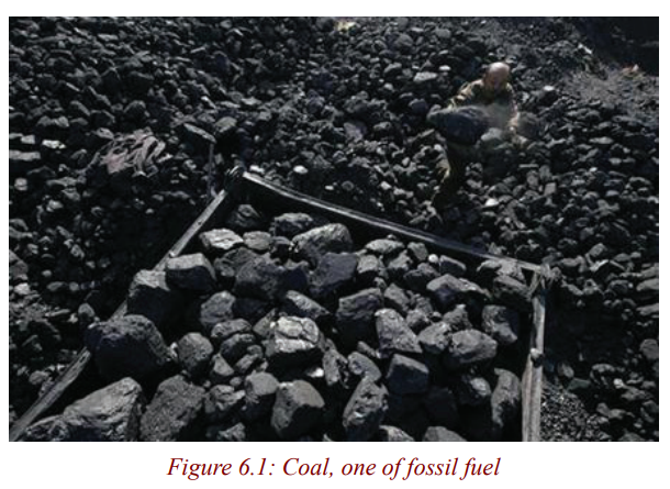
Rwanda’s main fossil fuel resource is methane gas. It is estimated that there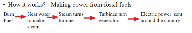
are 50 billion cubic metres of exploitable methane, which is the equivalent
of 40 million tons of petrol (TOE) laying at the bottom of the Lake Kivu
under 250 metres of water. Of the 55 billion cubic metres (cum) Standard
Temperature and Pressure, STP) of methane gas reserves, 39 billion cum
(STP) are potentially extractable. This represents a market value of USD 16
billion, equivalent to 31 million Ton Oil Equivalent (TOE). The technical and
economic feasibility of methane gas exploitation has been clearly demonstrated
since 1963 by the small methane extraction pilot unit at Cape Rubona with a
capacity of 5000 cum of methane per day at 80 % purity. The resource is
estimated to be sufficient to generate 700 mW of electricity for 55 years withRwanda’s share being 350 mW.
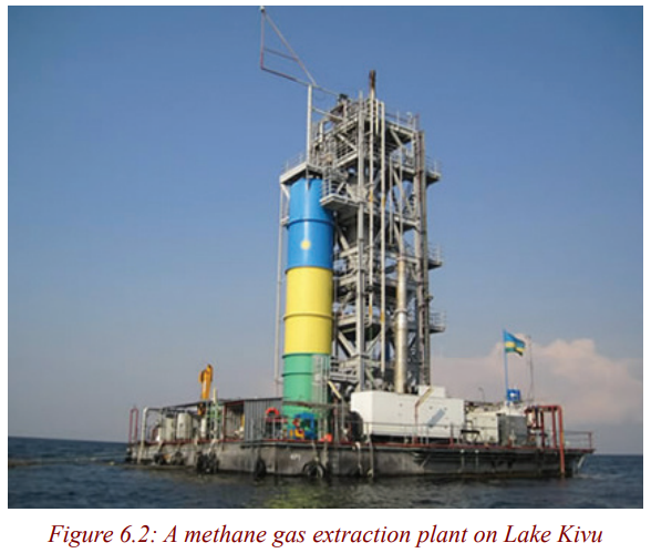
Nuclear fuel
Nuclear fuel is a material that can be ‘burned’ by nuclear fission or fusion toderive nuclear energy.
Most nuclear fuels contain heavy fissile elements that are capable of nuclear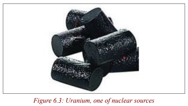
fission. When these fuels are struck by neutrons, they are in turn capable of
emitting neutrons when they break apart. This makes possible a self-sustaining
chain reaction that releases energy with a controlled rate in a nuclear reactor orwith a very rapid uncontrolled rate in a nuclear weapon.
“…Rwanda should choose a path to renewable energy—although nuclear is
the best other alternative; Rwanda does not have the technology to generatenuclear energy.
Even if Rwanda was ready to develop it despite the international laws and
regulations, nuclear energy poses a great danger especially, Rwanda being
located in a volcanic region. Nuclear energy for Rwanda in my opinion is a nogo option”. New times May 21, 2015
Renewable sources
Renewable energy is generally defined as energy that comes from resourcesthat
are not significantly depleted by their use, such as sunlight, wind, rain,
tides, waves and geothermal heat. Renewable energy is gradually replacing
conventional fuels in four distinct areas: electricity generation, hot water/space heating, motor fuels, and rural (off-grid) energy services.
Generally, Rwanda is well endowed with renewable energy resources, but most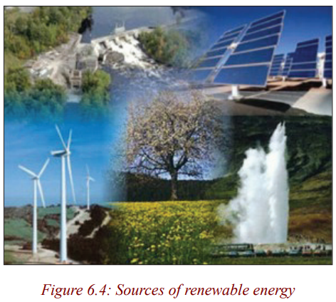
potential still remains untapped. Micro hydro-power in particular constitutes
a significant potential for rural power supply with many areas having ample
rainfall and most streams and rivers unexploited. Solar irradiation is high -
between 4-6 kWh/m2/day - but diffusion is hampered by high initial cost and
limitations on high load usage. Biogas is promising for thermal energy needs
for farms and small institutions, especially considering the large number ofhouseholds that own cows and other livestock.
Geothermal
Geothermal energy is from thermal energy generated and stored in the Earth.Thermal energy is the energy that determines the temperature of matter.
According to a study by Geothermal Energy Association, geothermal potential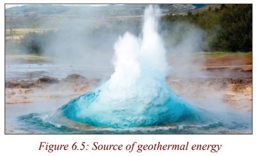
in Rwanda ranges from 170 - 340 MW. In Rwanda geothermal is a main
energy policy priority and forms a significant part of the 7-year electricity
development strategy including a very ambitious action plan targeting 150
MW of generation capacity by 2017 (which represents up to 50% of total
generation). A Geothermal Act and a geothermal exploration and development
paper have been drafted although a proposal for a feed-in-tariff for geothermal
still needs to be developed. Three sites (Rubavu, Karongi and Rusizi) were
identified already in the 1980’s with resource temperatures in excess of 150°C
which could be suitable for geothermal power generation. In early 2012, test
drilling commenced to explore possibilities to harness energy in Rubavu,
Karisimbi, Kinigi located in western region as well as Bugarama in southern
region. The Government has self-financed and contracted the first exploratorydrilling in 2013.
Biomass and biofuels
Biomass is biological material derived from living, or recently living
organisms. It most often refers to plants or plant-derived materials which
are specifically called lignocellulosic biomass. As an energy source, biomass
can either be used directly via combustion to produce heat, or indirectly after
converting it to various forms of biofuel. Conversion of biomass to biofuel can
be achieved by different methods which are broadly classified into: thermal,chemical, and biochemical methods.
In Rwanda, It has been observed that if an average household used 1.8 tonnes
of firewood in a year to satisfy its cooking needs with a traditional stove, the
same household would use 3.5 tonnes of wood if it were to switch to charcoal
with an improved stove. The use of charcoal in urban areas, in combination
with high urban growth rates, therefore is a worrisome phenomenon that
accelerates pressure on wood resources. Peat is also a resource the government
intends to promote use of. It is estimated that there exists in Rwanda estimated
reserves of 155 million tons of dry peat spread over an area of about 50,000
hectares. About 77% of peat reserves are near Akanyaru and Nyabarongo
rivers and the Rwabusoro plains Potential for Peat-to-Power Generation. Peat
in the Rwabusoro marshland and around the Akanyaru river can fuel 450 mW
of electricity generation for 25 years. Currently, a cement plant and someprisons utilize peat for cooking
Biogas has been introduced in the country many years ago and Rwanda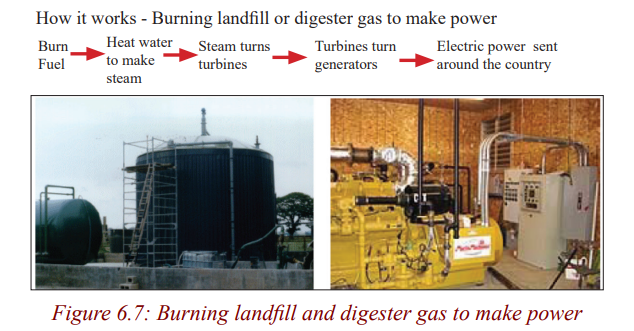
has gained international recognition for its program in prisons and large
institutions. The Government in 2008 announced a policy to introduce biogas
digesters in all boarding schools (estimated at around 600 schools), large
health centres and institutions with canteens to reduce the consumption of
firewood. This process started in 2010 but until today the focus has been
mainly on installations for schools. In total, about 50 large biogas digesters
have been constructed in institutions in Rwanda and the biogas systems that
have been installed in the prisons over the last decade have reduced firewoodconsumption by up to 40% and improved hygienic conditions.
Activities in the domestic biogas sector started much later. It is estimated that
over 120,000 households have dairy cows that are kept under zero grazing
conditions to reduce soil erosion and also due to lack of grazing areas. These
numbers are increasing due to the governments programs to increase thenumber of families with dairy cows.
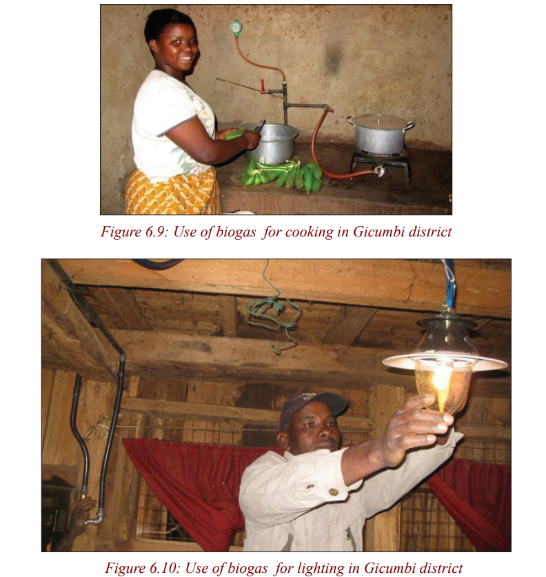
Solar energy (photovoltaic cells and solar heating panels)
Photovoltaic Cells
Solar energy, radiant light and heat from the sun, is harnessed using a range of
ever-evolving technologies such as solar heating, photovoltaic, concentratedsolar power, solar architecture and artificial photosynthesis.
The Rwandan government is set to commission the first utility-scale solar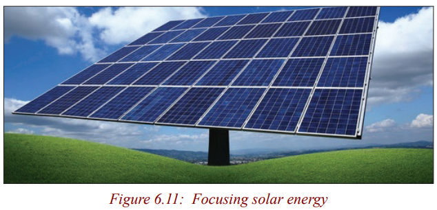
photovoltaic (PV) plant at eastern Rwanda’s Rwamagana district in August
2014 The project, with a production capacity of 8.5 mW, has commenced
testing, stated local reports. Dutch company Gigawatt Global is the developer
of the project, while Norwegian firm Scatec Solar has agreed to operate andmaintain the plant.
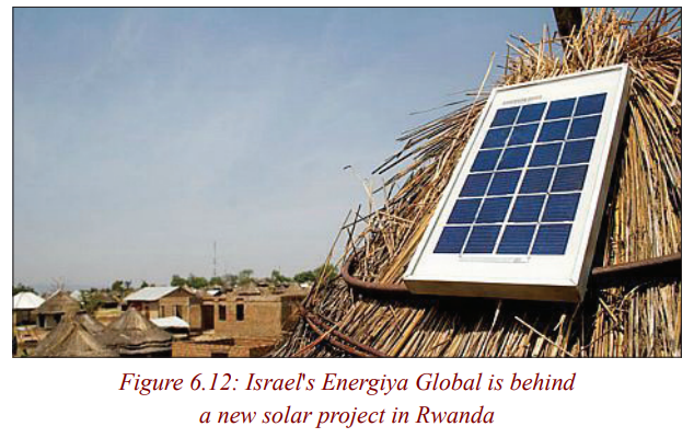
Solar Heating Panels
A solar thermal collector collects heat by absorbing sunlight. A collector is
a device for capturing solar radiation. Solar radiation is energy in the form
of electromagnetic radiation from the infrared (long) to the ultraviolet (short)wavelengths.
The term “solar collector” commonly refers to solar hot water panels, but may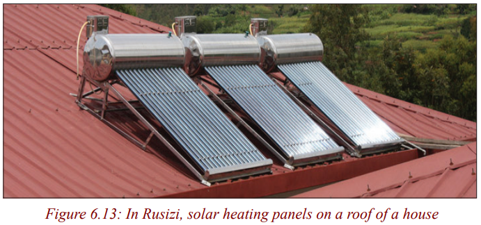
refer to installations such as solar parabolic troughs and solar towers; or basicinstallations such as solar air heaters.
Hydroelectric power, wind power and wave power
Hydroelectricity
Energy in water can be harnessed and used. Since water is about 800 times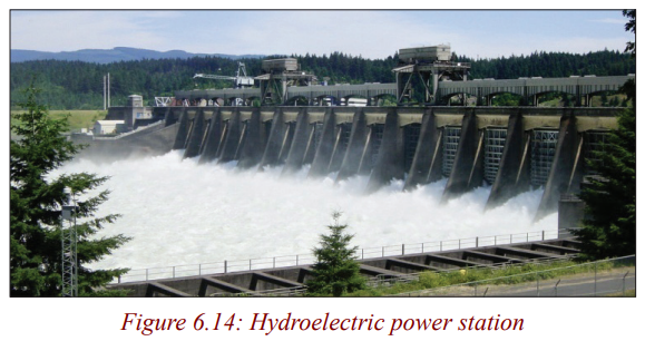
denser than air, even a slow flowing stream of water, or moderate sea swell,
can yield considerable amounts of energy. Hydroelectricity is the term
referring to electricity generated by hydropower; the production of electrical
power through the use of the kinetic energy of falling or flowing water. It is
the most widely used form of renewable energy, accounting for 16% of globalelectricity consumption.
The country currently has about 57 MW installed hydropower generating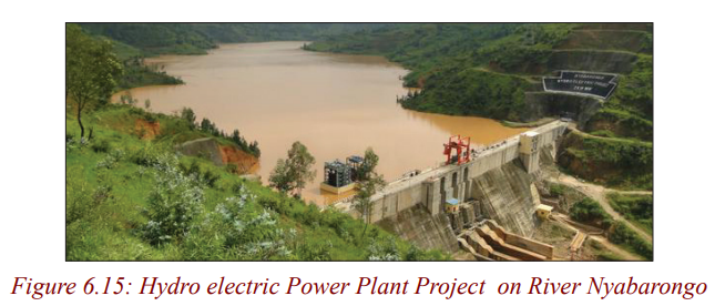
capacity. Hydroelectric power is mainly from the northern and southern parts
of the country (Musanze , Rubavu and Rusizi) namely from the following
power plants: Ntaruka, Mukungwa , Rubavu, Gihira as well as Rusizi 1 and
Rusizi 2. A number of new sources are supposed to come on line within
the coming years adding a capacity of 232 MW by 2013. This includes the
hydropower site Nyaborongo with 27.5 MW in Muhanga and Ngororero
Districts planned to come on line by February 2013 but currently experiencing
delays, and numerous mini/micro hydro plants adding up to 35 MW. The
new hydropower plant, Rukarara located in Nyamagabe district, Southern
Province, with 9.5 MW and costs of US$ 23.5 million was commissioned inJanuary 2011. Construction for this plant had already started in 2007.
Wind Power
Airflows can be used to run wind turbines. Modern utility-scale wind turbines
range from around 600 kW to 5 MW of rated power, although turbines with
rated output of 1.5–3 MW have become the most common for commercial
use; the power available from the wind is a function of the cube of the wind
speed, so as wind speed increases, power output increases up to the maximumoutput for the particular turbine.
Wind Potential in Rwanda has not been fully exploited for power generation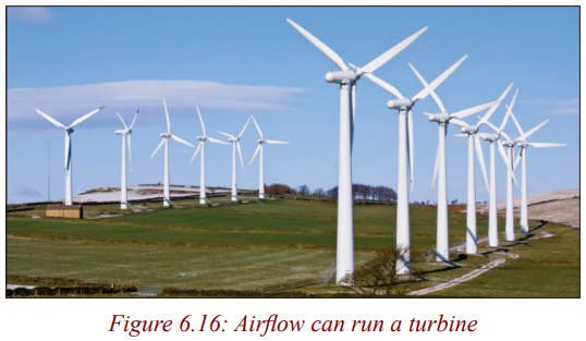
although potential wind power that Rwanda has in some areas may provide
with possible solutions such as water pumping, windmill and electricity
generation. A study of wind speed distribution has been made. (In this study,
the results have been found for the average wind speeds and directions for 3stations (Kigali, Rubavu and Huye) from 1985 to 1993.
These results can be summarised as follows:
• Direction of wind varies from 11 to 16°.
• Wind speed varies from 2 to 5.5m/s
The analysis of the wind energy possible solution for energy supply in rural
areas of Rwanda, was undertaken to estimate the wind power potential. In
total data from 4 stations (Kamembe, Huye, Nyagatare and Rubavu) have
been analysed by the National Meteorological Division in 1989. Once again,
the data from 3 synoptic sites (Kigali, Huye and Rubavu) are analysed by the
Weibull function. The considered data has been used to evaluate the annual
frequency of wind speed and the direction of wind, yearly variation of the
monthly average, annual and daily variation, and vertical profile of wind
energy potential. Nevertheless more detailed data is still required. In 2010 a
wind system was put in place to serve the Rwanda office of information RBA
on Mount Jali overlooking Kigali. This is the same site for the 250KW solar
system feeding to the grid. There is need for more thorough assessment of thewind potential in the country.
Wave Power
Wave power captures the energy of ocean surface waves, and tidal power,
converting the energy of tides, are the two forms of hydropower with futurepotential; however, they are not yet widely employed commercially.
Activity 2
Energy Source research
Purpose
Although most of the energy consumed in Rwanda comes from fossil fuel
sources, there are many other potential sources of energy available. In all
cases, there are pros and cons (advantages and disadvantages) to our use of
these sources. Some of the energy sources are limited by their availability
or environmental impact; others need technological improvements before
they can become widely used. For scientists and engineers, research is thebest way to learn about unknown topics.
In this section, we will examine information about energy sources and
how those sources are used to produce electrical energy. We can use this
information to help us understand the various pros and cons that affect
our use of different energy sources. In this activity, each group of students
will begin to become an expert on one aspect of each source of energy andreport their findings back to the class.
Procedure
1. Break into a group of 2-3 learners.
2. Choose or accept an assignment to research one particular question
about each source of energy.
3. Using the provided information packet, find the answer to your
question for all seven energy sources.
4. Once you have answered your question for all seven sources, answer
the two conclusion questions.As a class, we will fill in the energy sources chart based on your findings.
Research Questions
1. What is this energy source? Where can we find it in Rwanda?
2. How do we harness the energy? (How does it work?)
3. Are there different types or uses of this source? If yes, what are
the differences?
4. How is this energy source currently used? For example: At farms,
in industry etc. Could this source be used in a family home?
Note: Prepare a report summarizing your research and present the reportto the class.
Primary energy sources take many forms, including nuclear energy, fossil
energy-like oil, coal and natural gas - and renewable sources
like wind, solar, geothermal and hydropower. These primary sources are
converted to electricity, a secondary energy source, which flows through
power lines and other transmission infrastructure to your home and business.Activity 3
Discussion Questions
1. If you had to choose an energy system to tell your community about
based only on the aspect you researched, which system would you
choose? Why?
2. Why do we as a nation depend so much on fossil fuels? AND what doyou think we could do to reduce this dependence on fossil fuels?
Note: Prepare a report summarizing your research and present the reportto the class.
While listening to the other groups in your class present their information, list
some “pros” and “cons” (advantages and disadvantages) of using their energy
source to solve your problem. While listening to the students in your group
present their information, list some “pros” and “cons” of using that energysource to solve the energy problem.
Advantages and disadvantages of renewable and non-renewable energies
Activity 6
Do research in the library or internet and complete the task below
1. Complete the chart below about the basic types of renewable energyresources.
2. List those energy sources that are fossil fuels.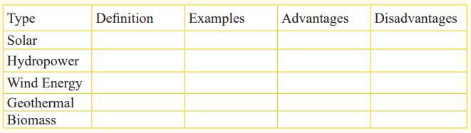
_____________________________________________________
__________________________________________________________________________________________________________
3. What main advantage do fossil fuels have over the renewable
energy resources?
_____________________________________________________
__________________________________________________________________________________________________________
4. What are two main disadvantages of fossil fuels compared to
renewable energy?
_____________________________________________________
__________________________________________________________________________________________________________
The sun, prime source of world energy
Solar energy comes from thermonuclear fusion; 30% of solar energy arriving
on higher layers of atmosphere are reflected in space. 47% of that energy are
absorbed by the ground and oceans during daytime and become the Earth’s
internal energy. The remaining 23% of solar energy are used in evaporation
of water of oceans. When it rains, a part of energy is transformed into
potential gravitational energy, stocked in mountains, lakes, which are the
sources of hydroelectric power. About 0.2% is used by convection currents
in atmosphere and creates wind energy. Finally 0.02% is absorbed by plantsduring photosynthesis and is stocked by them in form of chemical energy.
Plants are sources of biomass. Photovoltaic cells transform solar energy inelectrical energy.
The table below show the summary of energy sources
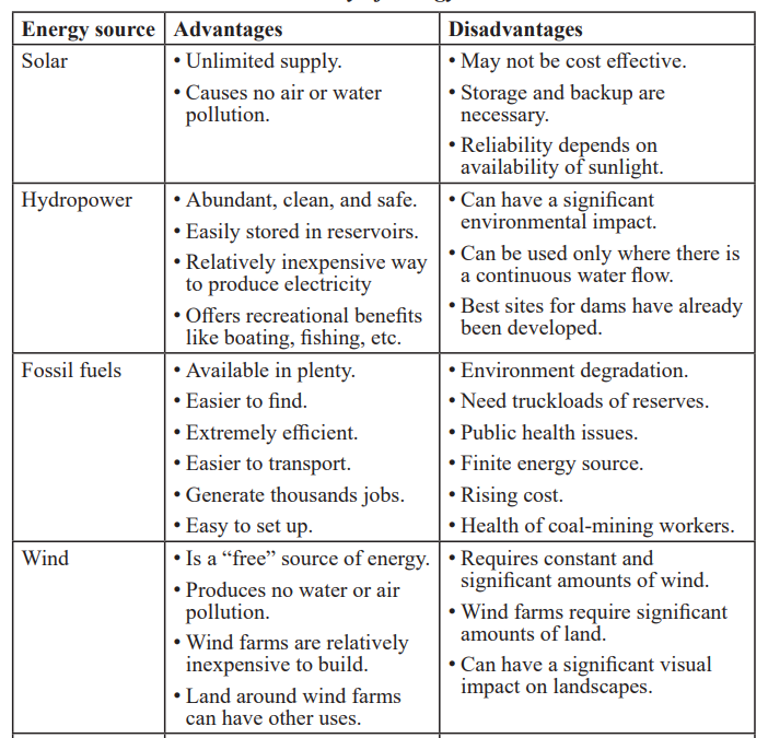
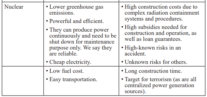
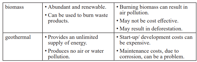
Extraction and creation of renewable and non-renewable energy sources
Activity 5
Creation of renewable and non renewable energy
From what you have already learned, you’ll do also research and tell
how these energies are created: Solar energy, hydropower, wind energy,
geothermal energy, and biomass. Try to find or to formulate how they areextracted.
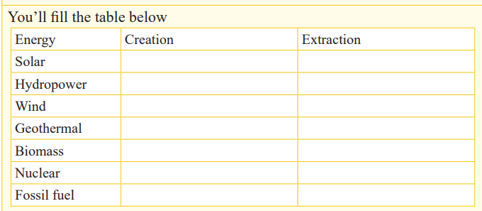
Creation
Non-renewable resources
A non-renewable resource (also called a finite resource) is a resource that
does not renew itself at a sufficient rate for sustainable economic extraction
in meaningful human time-frames. An example is carbon-based, organically-
derived fuel. The original organic material, with the aid of heat and pressure,becomes a fuel such as oil or gas.
Earth minerals and metal ores, fossil fuels(such as coal, petroleum, and natural
gas), nuclear fuels, and groundwater in certain aquifers are all non-renewableresources.
Natural resources such as coal, petroleum (crude oil) and natural gas take
thousands of years to form naturally and cannot be replaced as fast as they are
being consumed. Eventually it is considered that fossil-based resources will
become too costly to harvest and humanity will need to shift its reliance toother sources of energy. These resources are yet to be named.
Renewable resources
Natural resources, known as renewable resources, are replaced by natural
processes and forces persistent in the natural environment. There
are intermittent and reoccurring renewable and recyclable materials, which are
utilized during a cycle across a certain amount of time, and can be harnessedfor any number of cycles.
The production of goods and services by manufacturing products in
economic systems creates many types of waste during production and after
the consumer has made use of it. The material is then incinerated, buried in
a landfill or recycled for reuse. Recycling turns materials of value that wouldotherwise become waste into valuable resources again.
The natural environment, with soil, water, forests, plants and animals are
all renewable resources, as long as they are adequately monitored, protected
and conserved. Sustainable agriculture is the cultivation of plant and animal
materials in a manner that preserves plant and animal ecosystems over the
long term. The overfishing of the oceans is one example of where an industry
practice or method can threaten an ecosystem, endanger species and possibly
even determine whether or not a fishery is sustainable for use by humans.
An unregulated industry practice or method can lead to complete resourcedepletion.
Extraction
Resource extraction involves any activity that withdraws resources from
nature. This can range in scale from the traditional use of preindustrial societies,
to global industry. Extractive industries are, along with agriculture, the basis
of the primary sector of the economy. Extraction produces raw material
which is then processed to add value. Examples of extractive industries are
hunting, trapping, mining, oil and gas drilling, and forestry. Natural resources
can add substantial amounts to a country’s wealth, however a sudden inflow
of money caused by a resource boom can create social problems including
inflation harming other industries (“Dutch disease”) and corruption, leadingto inequality and underdevelopment, this is known as the “resource curse”.
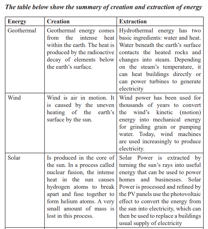
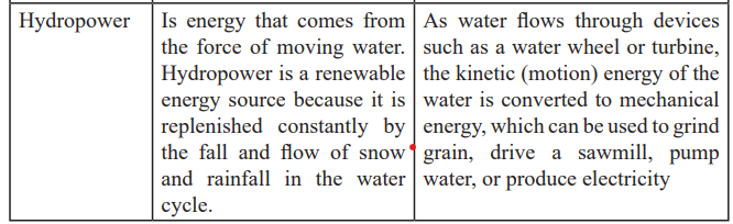
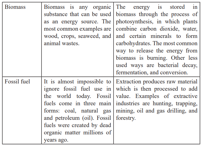
END UNIT ASSESSMENT
1. Differentiate between renewable and non-renewable energy
resources?
2. Using a table to distinguish renewable and nonrenewable resources:
Sun, coal, water, natural gas, wood; petroleum; wind; nuclear
fission; biomass
3. Which instrument is used to measure a wind energy?
4. What kind of energy will people be using in the future? Why?
5. What are benefits of renewable energy?
6. Why don’t people use more renewable energy now?
7. Are there reasons to use more renewables now rather than wait until
the non-renewables run out?
Unit 7 : Projectile and uniform circular motion
Key Unit Competence
Analyse and solve problems related to projectile and circular motion.
My goal
By the end of this unit, I will be able to:
* define and explain terms used in projectile motion.
* discuss the different applications of projectile motion.
* apply concepts of projectile and circular motion in real life.
* differentiate between projectile motion and circular motion.
Introductory activity
Take the case of a basketball player shooting the ball into the basket’s net
from a given distance at a given angle as shown in the figure below thenanswer to the following questions.
1.Discuss on the motion of the ball after being shot
2.Discuss other situation where one can observe such a king of motion.
3.Explain how this kind of motion is important in normal life activities.
4.Contrast between projectile motion and circular motion using typicalexamples.
Introduction
We have different kinds of sports, for examples; football, netball, tennis
amongst others. A lot of reasoning is needed while playing football to score
one of which is to kick a ball at a certain angle (i.e. to move above the ground).
We say that the ball is projected. This also applies to basket ball; the ball to
enter the round ring for a score it has to be thrown at a certain angle. Hence,
projected. The same principle is used by the military in shooting and launchingtheir missiles.
Projectile Motion
Activity 1: Field study
Aim; To study motion of bodies in free space
a) Out of class, (in pitch,or in school compound), throw a
ball,a stone or any body upward.
b) State what happens.
c) Hold a ball in your hands and release it to fall.
d) Is the motion of the ball same as in the first case?
e) Note down your observation.f) Relate your observations for bodies moving linearly.
Caution
While throwing a stone or any body, take care so that it does not harm you.
We can define a projectile as any body thrown into space/air. The path
taken is called a trajectory. The motion of a projectile unless taken otherwise
is a free motion under gravity. We assume that air resistance is negligible in
this kind of motion.
We have three cases: oblique projection, vertical projection and horizontalprojection.
Projection at an angle above the horizontal
• Study the picture below carefully.
• Go outside class and try to kick the ball so that it does not roll on the
ground.
• State when will the ball cover a long horizontal range. (State downthe conditions for that to occur).
From the figure above, if the ball is kicked so that it does not roll on the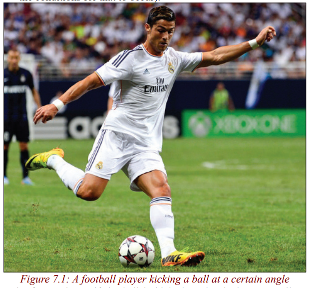
ground, it will move at certain angle relative to the ground.
Activity 2
a) In the ground, kick the football individually.
b) By observing, the flight of the ball state whether it will cover a
longer horizontal distance when it is projected at a large angle or a
small angle.
c) Explain your observation and note down any key points in your
book.
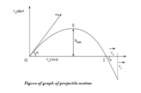
Upward projection
From the figure above, a football player can kick the ball and it takes themotion of a projectile.
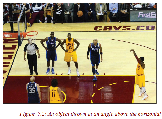
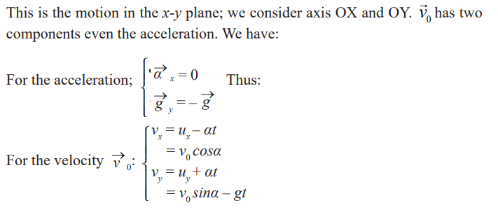
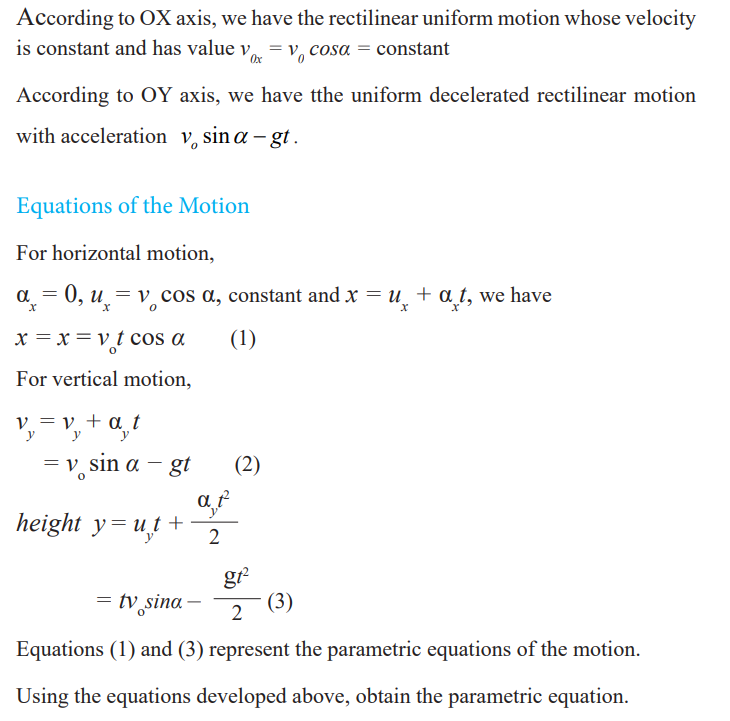
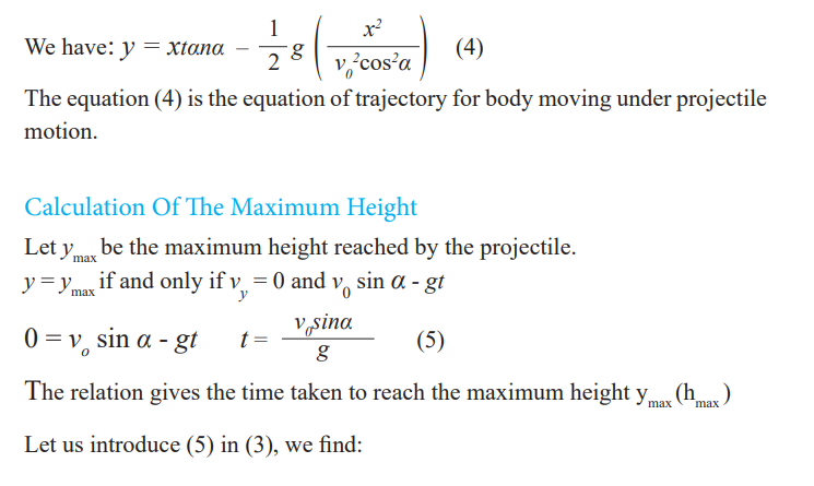
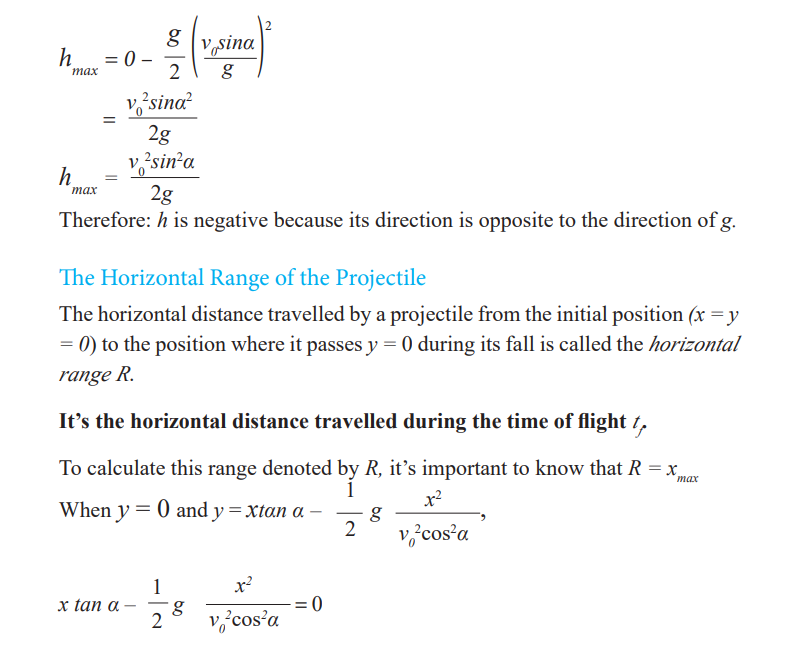
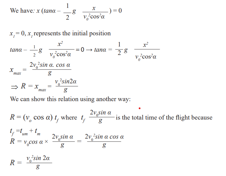
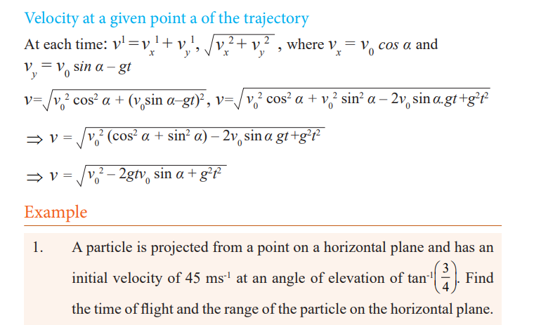
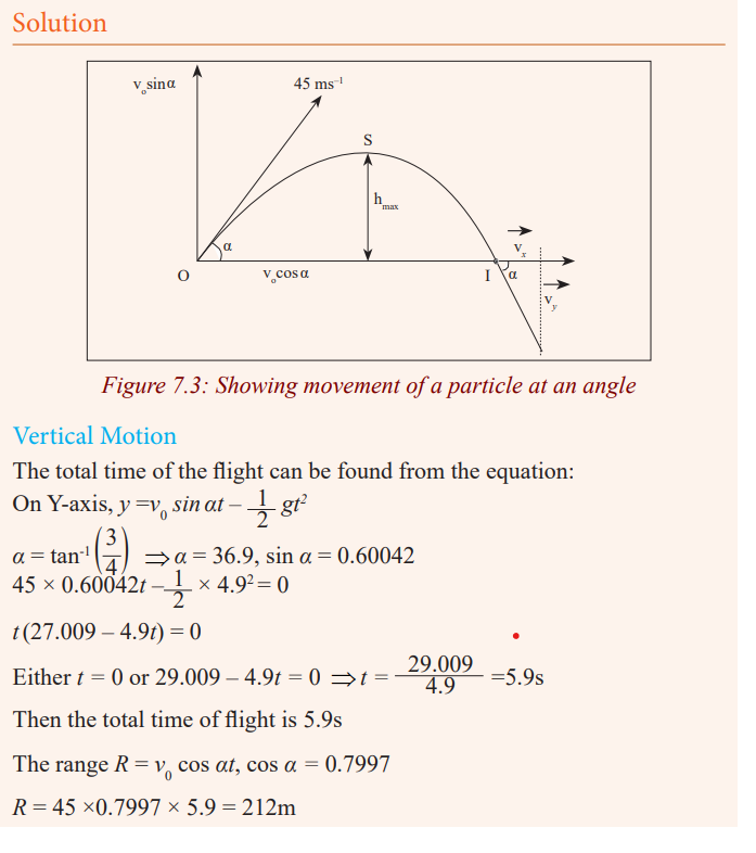

Horizontal projection
Activity 3
Place a stone on top of a table.
Displace it so that its motion takes the shape below.
Try to observe the motion carefully.Note down what you observe and share it with your class members.
Take care
In throwing the stone / displacing it, you should take care so that it does nothit you because it may harm you.
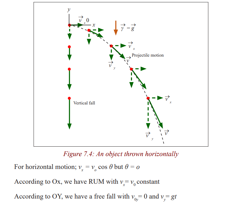
Activity 4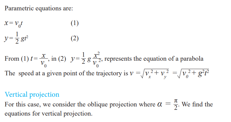
Using the information given above;
a) Derive the equations for the motion.
b) Study the picture below and do the same.c) State the condition when the body attains maximum height.
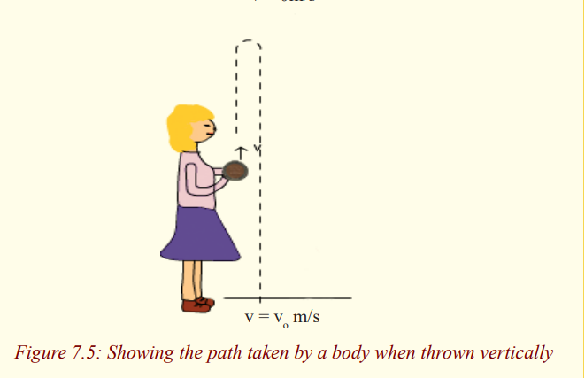
Examples of application of projectile motions are as follow:
• Football kicked in a game
• A cannonball fired from a cannon.
• A bullet fired from a gun
• A disc thrown in the sport of discus throw.
• The flight of golf ball.
• A jet of water escaping a hose.
• Motorcycles and cars jumping in extreme sports
Application activity 7.1
1. A gun has a muzzle velocity of (i.e. a shell leaves the gun with
an initial speed of ). Find the horizontal range of the gun when
the angle of projection is 300. Find also the maximum horizontalrange of the gun.
2. A stone is thrown from the top of a cliff (as shown in figure below)
70 m high at an angle of 300 below the horizontal and the sea 20
m from the bottom of the cliff. Find the initial speed of the stoneand the direction in which it is moving when it hits the sea.
3. A man fires a rock out of a slingshot directly upward. The rock has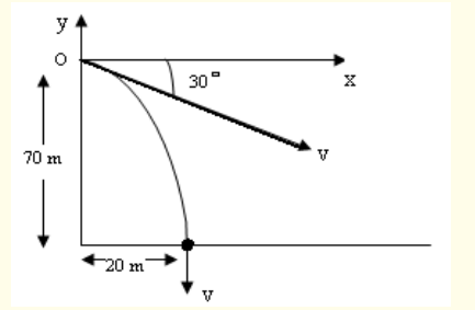
an initial velocity of . How long will it take for the rock to returnto the level he fired it at?
Circular motion
Activity 5
Study carefully the motion of the ball shown below.
State what would happen if at any point the thread holding the ball breaks?Note and record your observation.
A motion is said to be circular if the trajectory is a circle of constant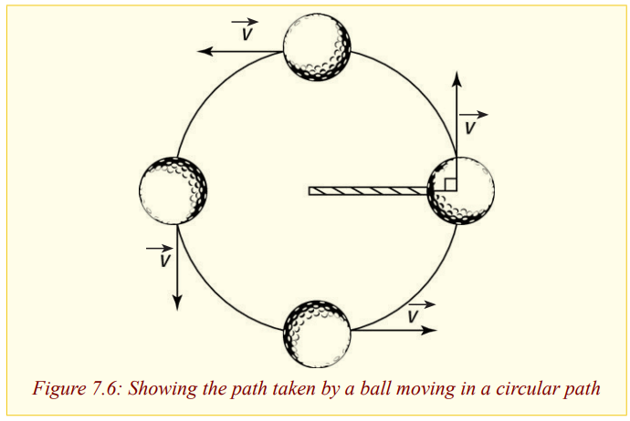
radius R.
The motion is uniform if the body describes in equal angular displacements
in equal times.. Even if the motion is uniform, it has an acceleration becausethe velocity changes after every moment since its direction keeps changing.
Angular displacement θ
Definition of key terms in circular motion
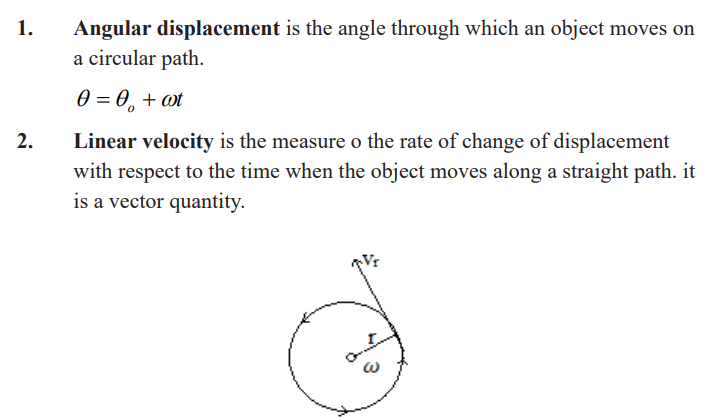
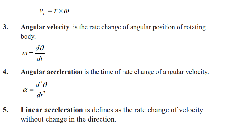
Centripetal acceleration
As we said, in a circular uniform motion, there is acceleration. This acceleration
is called centripetal acceleration. The easiest way of proofing this formula isas follow:
Consider an object moving with a constant speed (a scalar which has nodirection) round a circle of radius r.
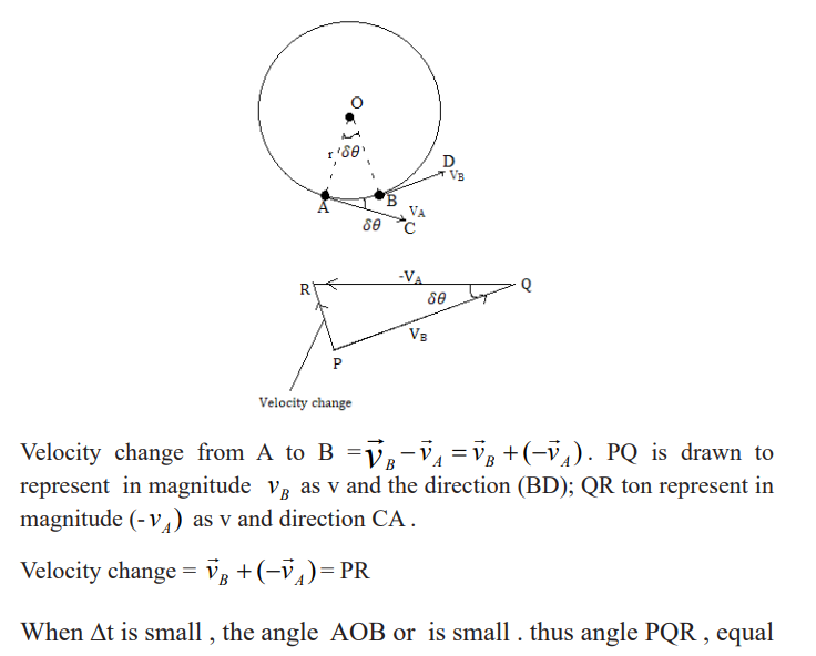
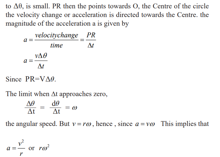
Periodic time, frequency
Activity 6
* Go to the play ground.
* Make sure you round the playground two times.
* Note and observe the time taken to make one complete revolution.
* What do you call the time taken to move around the play ground.
From the activity 6, you made two rounds in a given time. The number of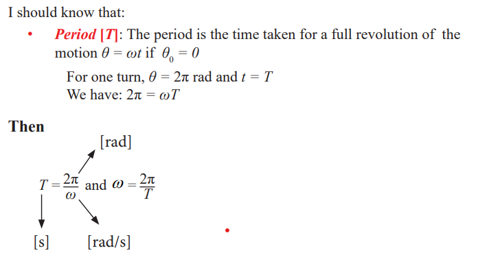
rounds made in a Unit time is called frequency
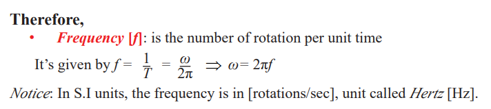
In summary
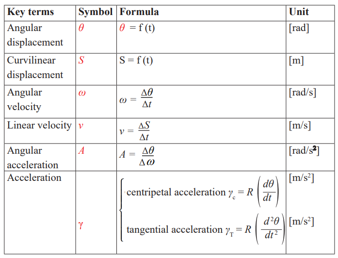
Distance time-graph of a uniform circular motion
When an object executes a circular motion of constant radius R, its projection
on an axis executes a motion of amplitude a that repeats itself back and forth,
over the same path.
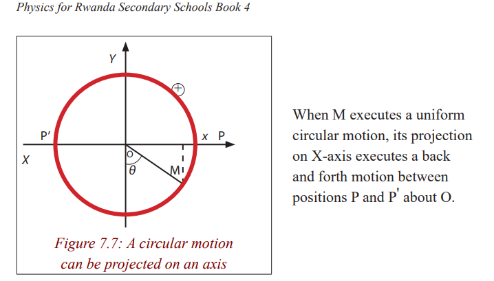
Considering the displacement and the time, we find the following graph
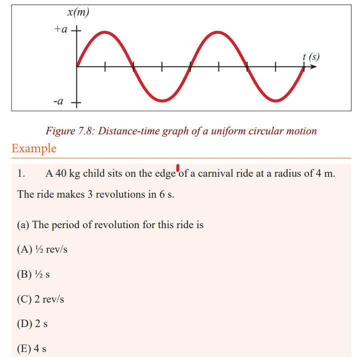
(b) The speed of the child is most nearly
(A) 4 m/s
(B) 12 m/s
(C) 24 m/s
(D) 120 m/s
(E) 360 m/s
Solution
2.A 150 g ball at the end of a string is revolving uniformly in horizontal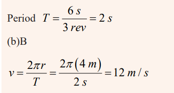
circle of radius 0.600 m; the ball makes 2.00 revolutions in a second. Whatis its centripetal acceleration?
SolutionIf the ball makes two complete revolutions per second then the Period is
Centripetal force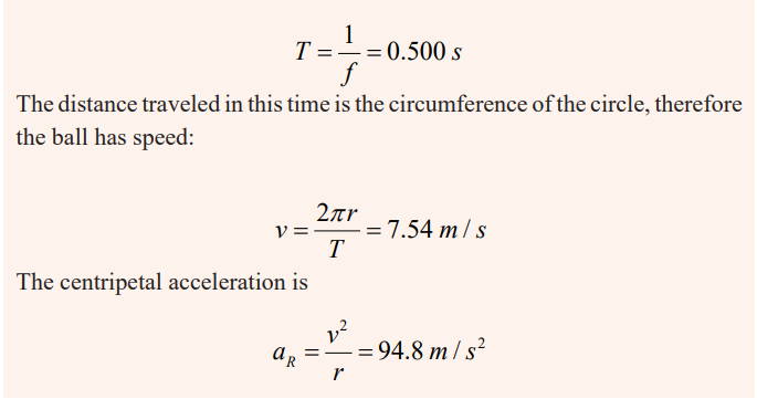
If you try to move / run in a circular path, you will finally notice that you keep
moving in a circle even when you try to stop. There is a force that keeps youmore in a circular path called centripetal force.
Since a body moving in a circle (or a circular arc) is accelerating, it follows
from Newton’s first law of motion that there must be force acting on it to causethe acceleration.
This force, like the acceleration, will also be directed toward the centre and
is called the centripetal force. The value F of the centripetal force is given byNewton’s second law, that is:
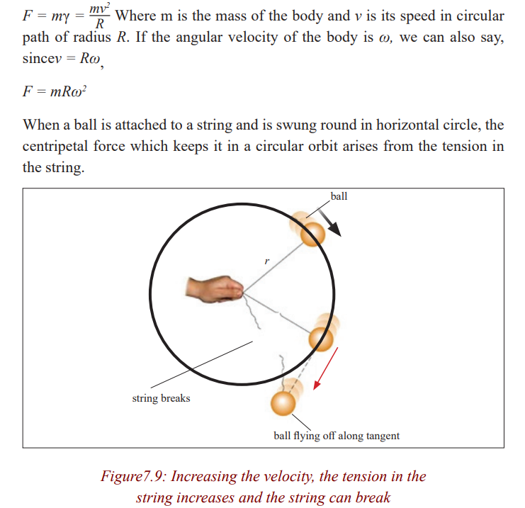
Example
1. A 40 kg child sits on the edge of a carnival ride at a radius of 4 m. The
ride makes 3 revolutions in 6 s. The force which is holding the child on theride is most nearly
(A) 30 N
(B) 160 N
(C) 320 N
(D) 1440 N
(E) 2880 NSolution
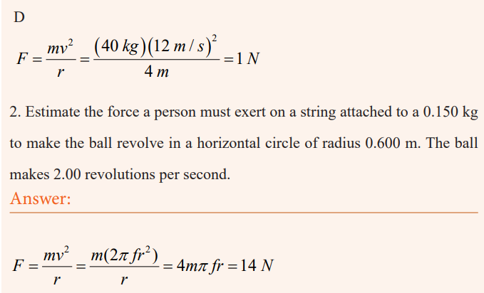
Application of circular motion
Vertical and horizontal circle
Vertical circle
Taking the approach that the ball moves in a vertical circle and is not
undergoing uniform circular motion, the radius is assumed constant, but the
speed v changes because of gravity. Nonetheless, the formula of centripetalacceleration is valid at each point along the circle, and we use it at point 1 and
2. The free-body diagram is shown in the figure 8.10 for the positions 1 and 2.
a) At the top (point 1), two forces act on the ball: the force of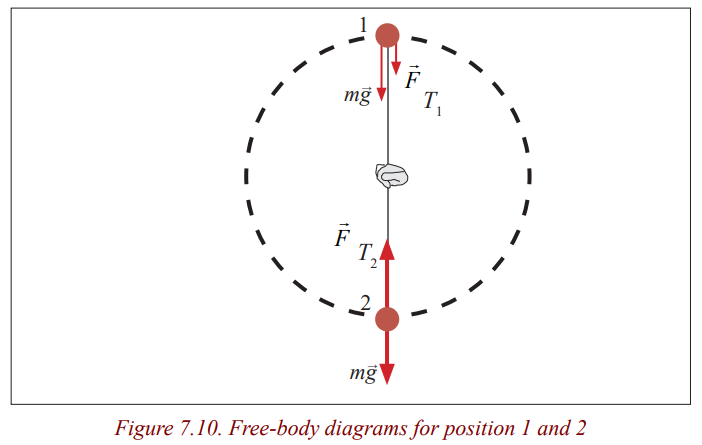
gravity and the tension force the cord exerts at point 1. Both
act downward and their vector sum acts to give the ball its
centripetal acceleration. We apply Newton’s second law, for t
a vertical direction, choosing downward as positive since theacceleration is downward (toward the centre):
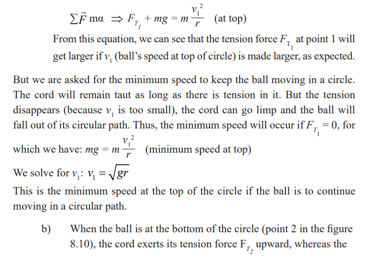
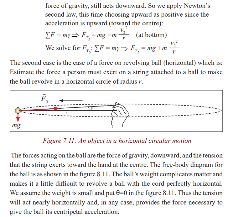
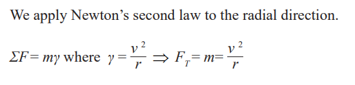
Example
A puck of mass 0.500 kg is attached to the end of a cord 1.50 m long. The
puck moves in a horizontal circle as shown in the figure. If the cord can
withstand a maximum tension of 50.0 N, what is the maximum speed at
which the puck canmove before the cord breaks?
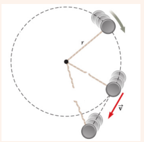
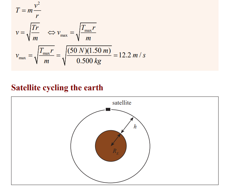
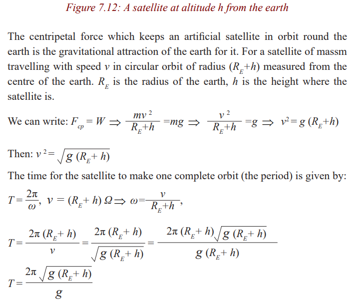
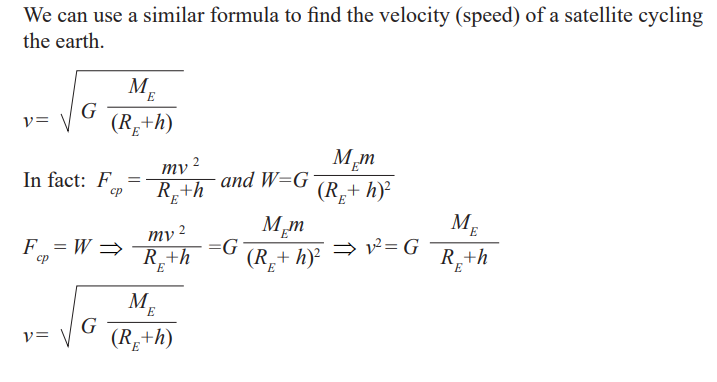
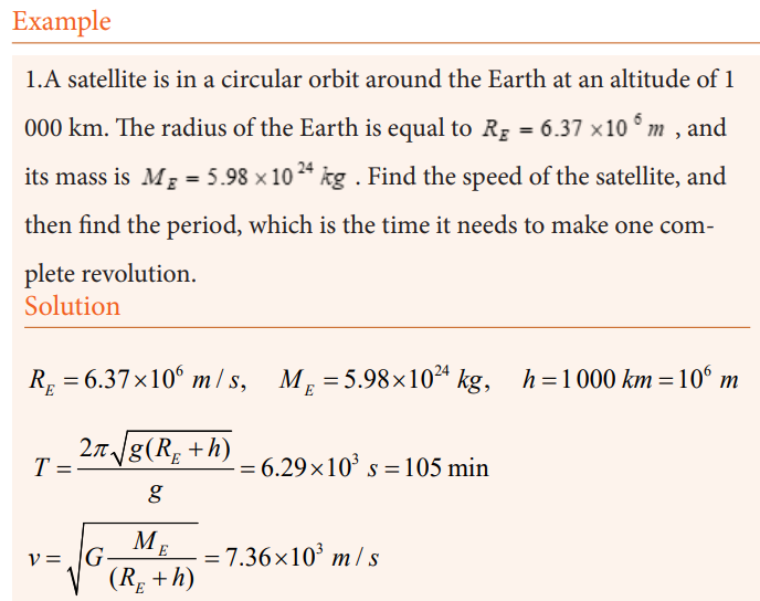
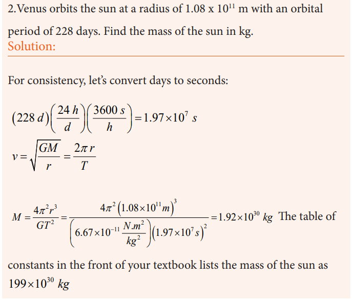
Conical pendulum
Activity 7
DO THIS!
* Tie a thread of about 50cm on retort stand.
* On a thread, tie a pendulum bob.
* Displace the bob through a certain angle.
* Displace the bob through a certain angle. What do you observe.
* Release the bob to move through a certain angle so that it moves in a
horizontal circle.
* Try to investigate forces acting in the bob.
* Relate your findings to fig. 8.13.
A small object of massm is suspended from a string of length L. The object
revolves with constant speed v in a horizontal circle of radius r, as shown in
Figure 8.13. Because the string sweeps out the surface of a cone, the system isknown as a conical pendulum.
Let us find an expression for v.
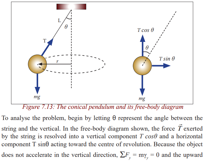
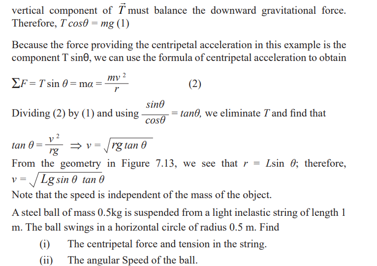
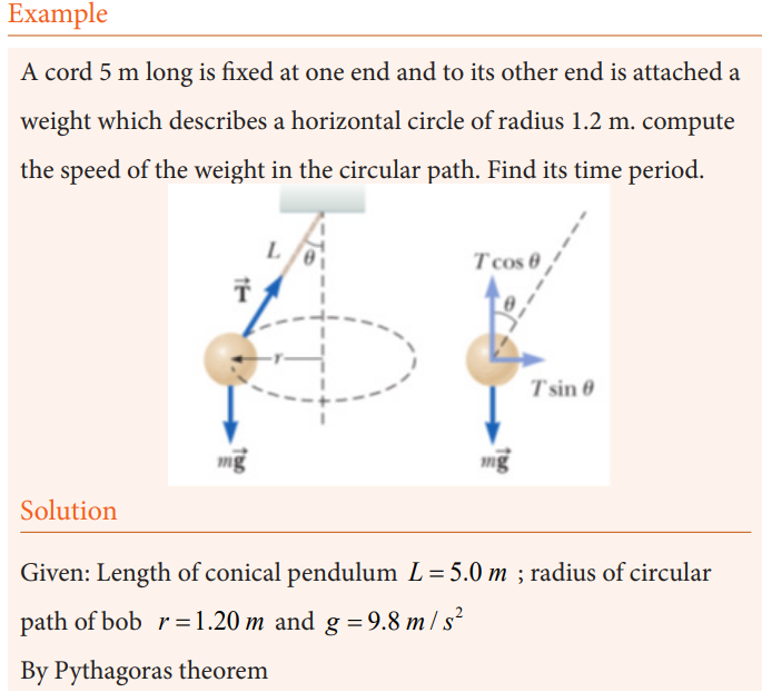
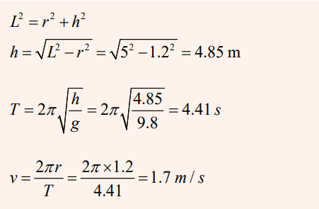
Road banking
Circular motion on JOB
Activity 8
A car negotiating a corner
The successful negotiation of a bend on a flat road therefore depends on the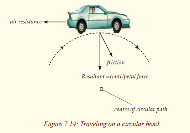
tyres and the road surface being in a condition that enables them to provide a
sufficiently high frictional force, otherwise skidding occurs. Safe corneringthat does not rely on friction is achieved by “banking” the road.
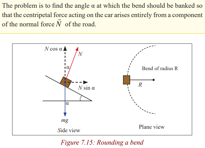
The equation shows that for a given radius of bend, the angle of banking is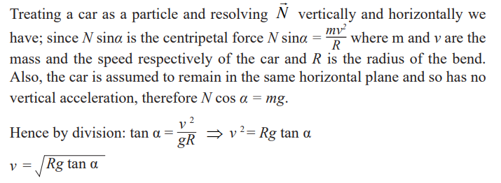
only correct for one speed.
Spinning dryer is also known as tumble dryer is a powered household
appliance that is used to remove moisture from a load of clothing, beddinganother textures, usually shortly after they are washed in a washing machine.
Example
1. The car has a mass m and a speed v as it moves around the track
of radius R. Which of the following expressions can be used to findthe value of the coefficient of friction between the tires and the road?
Career centre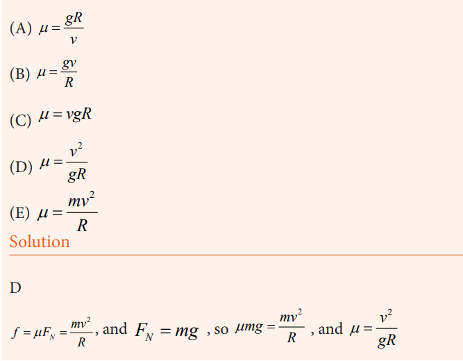
Learn more about careers in physics where projectile and circular motion areapplied.
END UNIT ASSESSMENT
1. A body is projected upwards from the level ground at an angle of
500 with the horizontal has an initial speed of 40 m/s. how long willit be before it hits the ground?
2. A body is projected downwards at an angle of 300 with the
horizontal from the top of a building 170m high. Its initial speed is
40m/s.
a) How long will it take before striking the ground?
b) Find out how far from the foot of the building the body will
strike,c) What the angle with the horizontal?
3. A body is projected from the ground at the angle of 300 with
the horizontal at an initial speed of 128m/s, ignoring air friction,
determine:
a) In how may seconds, it will strike the ground?
b) How high it will go?c) What is its range will be?
4. A ball is thrown upwards at an angle of 300 to the horizontal and
lands on the top edge of a building that is 20m away, the top edge is5m above the throwing point. How fast was the ball thrown?
5. A projectile is fired with initial velocity v0=95m/s at an angle .
After five seconds it strikes the top of hill. What is the elevation of
the hill above the point of firing? At what horizontal distance fromthe gun does the projectile lands?
6. 6. A ball is thrown from the top of the one building towards a tall
building 50m away. The initial velocity of the ball is 20m/s at 400
above the horizontal. how far above all below its original level, willthe ball strikes the opposite wall?
7. A projectile is fired with horizontal velocity of 330m/s from the top
of a cliff 80m high.
a) How long will it take for the projectile to strike the level
ground at the base of the cliff?
b) How far from the foot of the cliff will strike?c) With what velocity will it strike?
8. A 0.3kg mass attached to 1.5m long string is whirled around the
horizontal circle at a speed of 6m/s.
a) What is the centripetal acceleration of the mass?b) What is the tension of the string?
9. (Moderate), a race car, moving at a constant tangential speed
of 60m/s, takes one lap around a circular track in 50 seconds.Determine the magnitude of the acceleration of the car.
10. An object that moves in uniform circular motion has a centripetal
acceleration of 13m/s2. If the radius of the motion is 0.02m, what isthe frequency of the motion?
11. Find the centripetal acceleration for a n object on the surface of aplanet with the following characteristics: radius and 1day seconds.
12. An 8.0g cork is swung in a horizontal circle with a radius of 35 cm.
it makes 30 revolutions in 12 seconds. What is the tension in thestring? (Assume the string in nearly horizontal).
13. A 15g stopper is swung in a horizontal circle with a radius of
0.80meters. The tension in the string is 1.5Newtons. Find the speed
of the stopper and determine how long it takes to complete 30revolutions. (assume the string is very nearly horizontally)
14. A brass ball with a mass of 120 grams is suspended from that is
60.0 cm long. The ball is given a push and it moves in a horizontal
circle. The string is not nearly horizontal. It forms an angle of just
22.6 degrees from the vertical. (this is sometimes called a conical
pendulum because the string sweeps out the surface of a cone.
a) Draw free body diagram indicating the forces acting on the
ball.
b) What is the y-component of the tension force equal to? how
do you know?
c) Use trigonometry to find the x-component of the tension
force.
d) What is the radius of the ball’s motion?e) Use your answer to c and d to find the speed of the ball
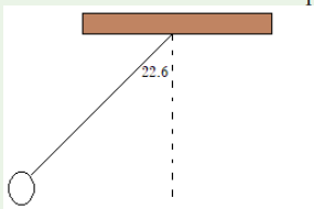
Unit 8 :Universal gravitational field and potential
Key Unit Competence
Explain the gravitational field, gravitational potential and their applications in
planetary motion.
My goals
By the end of this unit, I will be able to:
* explain universal gravitation field.
* describe the factors affecting force of gravity.
* state and explain Kepler’s laws of planetary motion.
* investigate planetory motion using computer simulation.
Link to other subjects
Geography and Astronomy (Landslides, motion of planets and satellites)
Chemistry (Electrons orbiting the nucleus).
Introductory activity
In observatory, people can see different heavenly bodies such as planets,
stars, moons, asteroids, comets and others moving in the universe. The
most question that people ask themselves is to know what hold those bodiesin their positions in the universe.
Questions
1. Discuss on what you think maintain planets in their position when
revolving around the Sun.
2. Discuss the factors that the motion planets depend on.
3. Give other examples of bodies that use same properties in the casestudy above.
Introduction
The Universe is composed of different planets one of which is the earth.
All objects on the earth remain on it. They cannot move away unless acted on
by external forces. This shows that there is a region around it that provides aforce that attracts these earthly objects.
Since the earth is part of the universe it follows that a round the universe thereis attracting field.
This is called universal gravitational field.
Universal gravitational field potential
To have potential is to have energy, therefore gravitational field potential is theability of gravity to attract other objects.
Gravitational field
Questions to think about!
1. What force that unites us as Banyarwanda?
2. How do you feel if you come close to a fellow munyarwanda when
you find him/her outside our country?
Relate the situation to the force around the earth.3. What makes you feel attracted to your fellow munyarwanda?
A field is a region of space where forces are exerted on objects with certainproperties.
The diagram represents the Earth’s gravitational field. The lines show thedirection of the force that acts on a mass that is within the field.
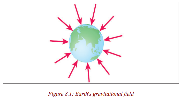
This diagram shows that:
• Gravitational forces are always attractive – the Earth cannot repel
any objects.
• The Earth’s gravitational pull acts towards the centre of the Earth.
• The Earth’s gravitational field is radial; the field lines become lessconcentrated with increasing distance from the Earth.
The force exerted on an object in a gravitational field depends on its position.
The less concentrated the field lines, the smaller the force. If the gravitationalfield strength at any point is known, then the size of the force can be calculated.
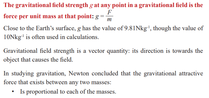
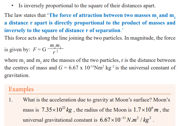
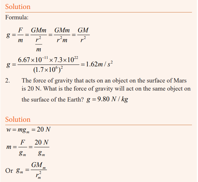
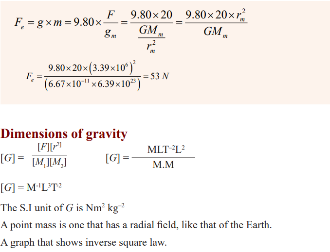
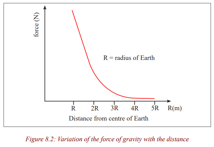
Gravitational potential energy
Potential and potential energy
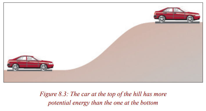
Question about fig. 8.3
• The car at the top of the hill has more potential energy than the
one at the bottom, but relative to ground level they both have zero.why?
• Note and record in your notebook your analysis.
Using this reference point:
• All objects at infinity have the same amount of potential energy; zero.
• Any object closer than infinity has a negative amount of potential
energy, since it would need to acquire energy in order to reachinfinity and have zero energy.
The gravitation potential energy is defined as the energy possessed by objectbecause of its position in a gravitational field.
The gravitational potential at a point in a gravitational field is the potentialenergy per unit mass placed at that point, measured relative to infinity.
Calculating potential and potential energy
When an object is within the gravitational field of a planet, it has a negative
amount of potential energy measured relative to infinity. The amount of
potential energy depends on:
• The mass of the object.
• The mass of the planet.
• The distance between the centres of mass of the object and theplanet.
The Centre of mass of a planet is normally taken to be at its centre.
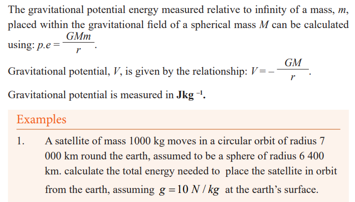
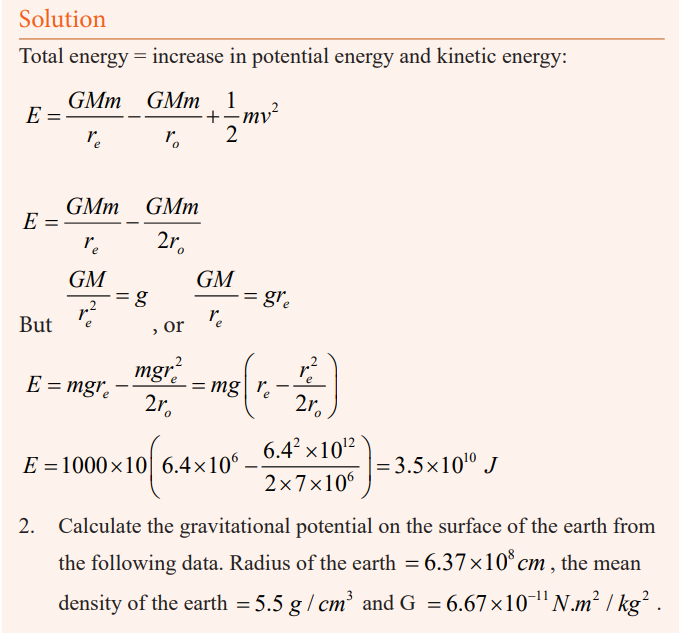
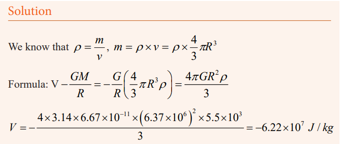
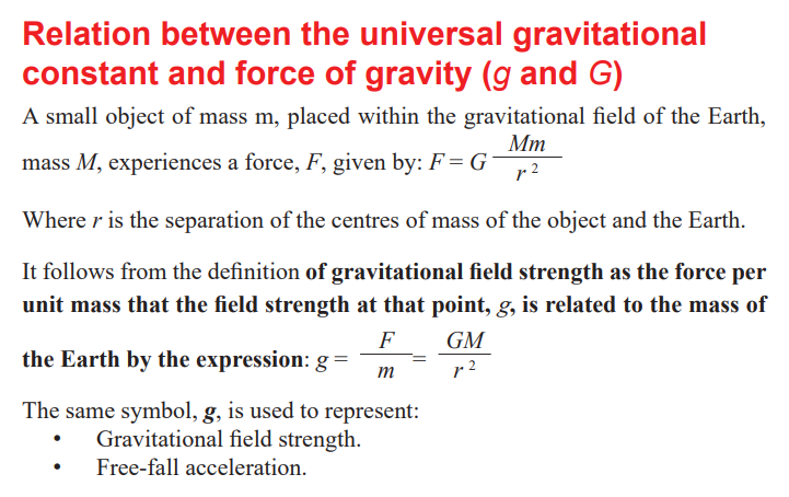
Kepler’s Laws
Activity1: Field work
As a class, let us visit one of the roundabouts (where three roads meet).
Try to see/check how cars, motorcycles, bicycles move around it.Qn i) Does the features on a roundabout move?
Assuming a roundabout to be a sun and vehicles to be planets, what can
you say?
1. Discuss your findings in groups of 5 members.
2. Present your findings to the whole class.
3. Note down the observation.4. Present your work to the teacher for marking.
Activity 2
We can relate the movement of the minute hand as the movement of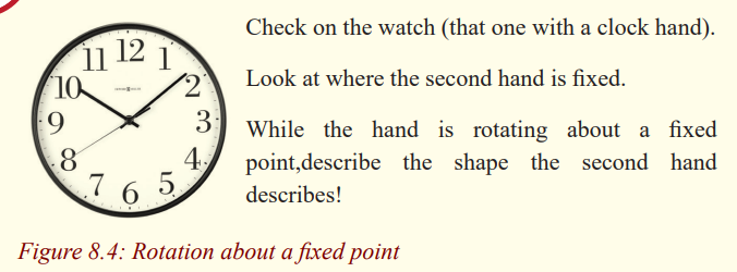
planets about the sun.
Kepler’s first law: The path of each planet about the sun is an ellipse with thesun at one focus(or planets describe ellipse about the sun as one focus).
Kepler’s second law: The line joining the sun to the moving planet sweeps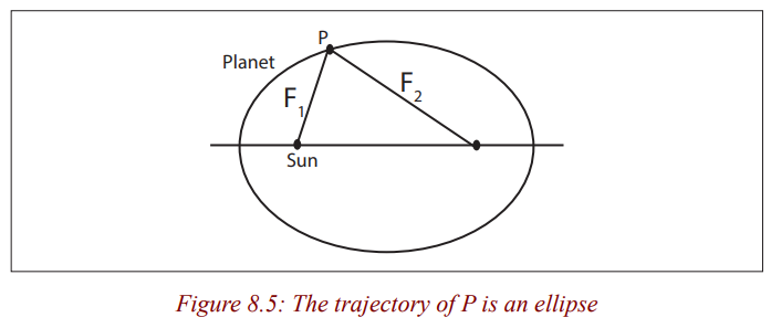
out equal areas in equal times.
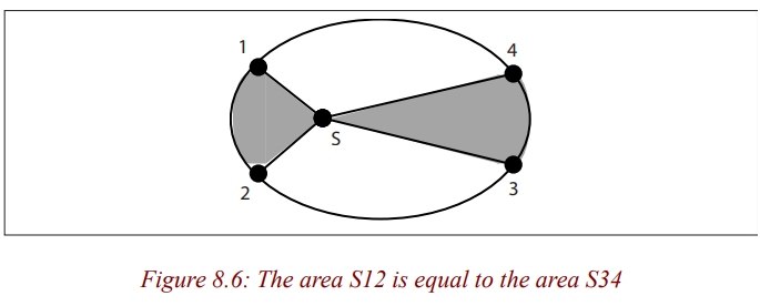
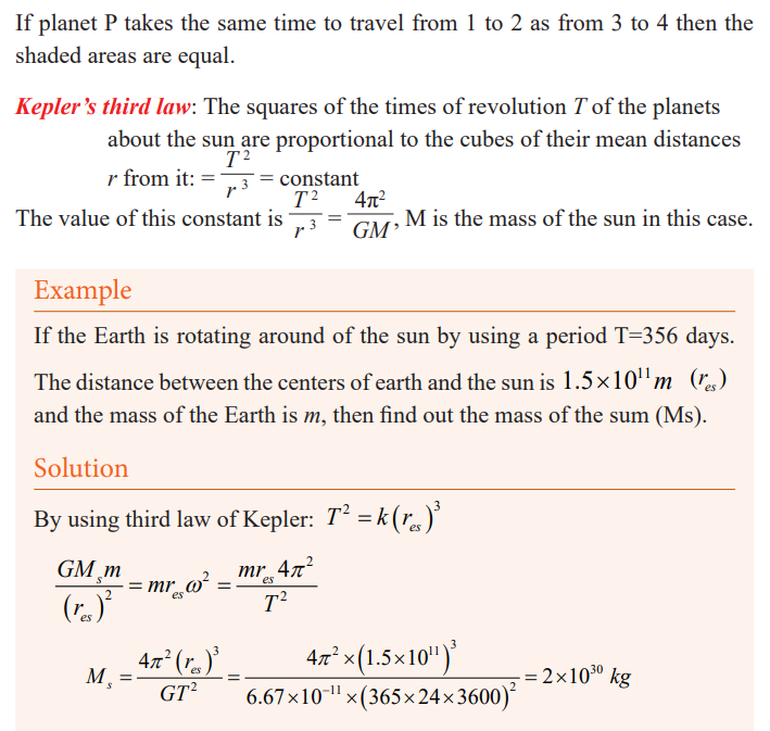
Proof of Kepler’s third law
Activity 3
• Using Newton’s law of gravitation (Formula) and the formula that
keeps the planet in circular paths (Formula for centripetal force),Derive expression for Kepler’s third law of planetary motion
• Put your derivation in your notebook after discussing it with yourfriends.
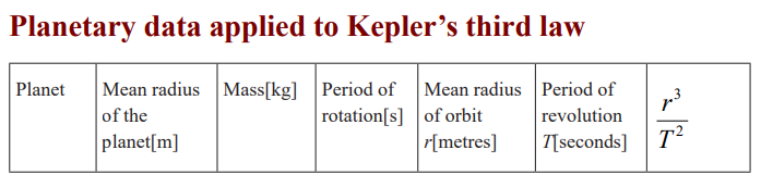
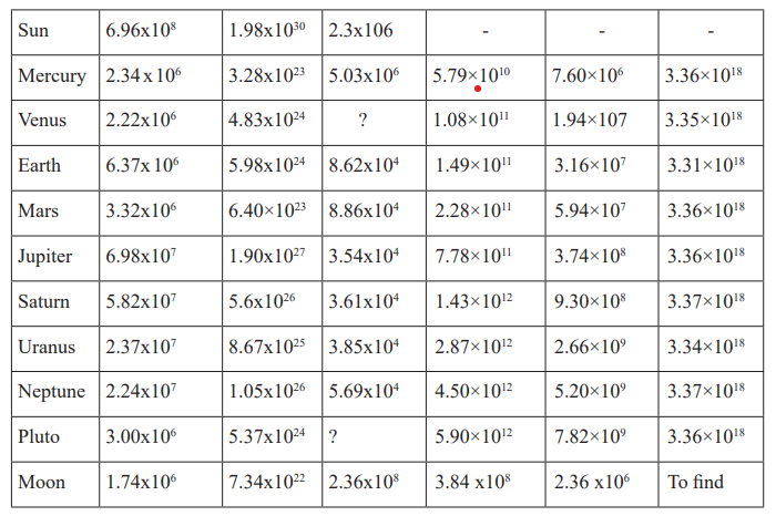
Examples
1. Calculate the force of gravity between two bowling balls eachhaving a mass of 8.0kg, when they are 0.50m apart.
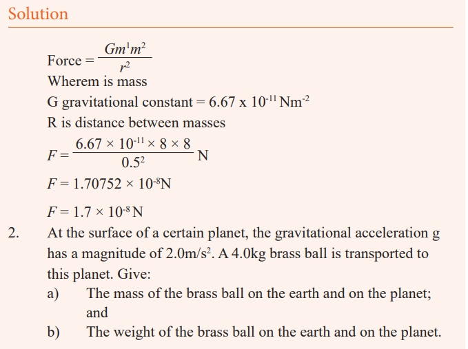
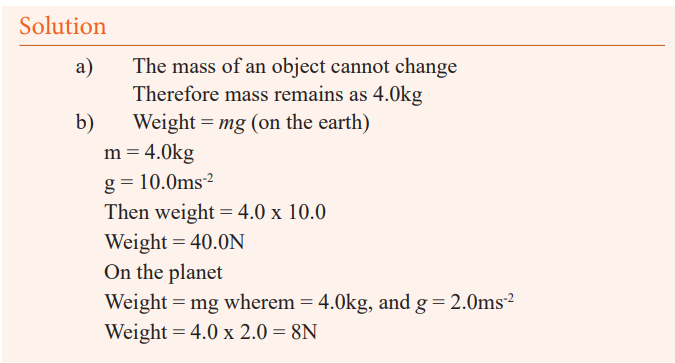
END UNIT ASSESSMENT
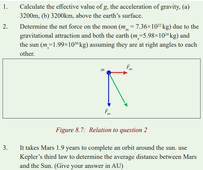
Unit 9 : Electric field and electric potential
Key Unit Competence
Analyze the electric field and electric potential.
My goals
By the end of this unit, I will be able to:
* define electric field and electric potential.
* explain the relationship between electric potential and electric field
intensity.
* describe functioning of lightening arrestors.* identify the dangers of lightening and how to avoid them.
Introductory activity
When you pass nearby an electric power station, you may notice some signpost as shown in figure below.
This is to show that, the high voltage on the grid may affect people who
dares to approach it.
Questions
1. Discuss about the reasons behind the information given by the sign post.
2. Is it possible that electricity can affect someone without touching the
wires (cables)?
3. Discuss other areas where you can get such sign post and explain thereason behind.
Introduction
Have you ever heard sound due to lightening? If yes, what do you think was
the cause?If not, ask your friend in your class, at home, or neighbour about lightening.
Scientifically, lightening and thunder are effects of electric charges created inspace (will be discussed later).
Attraction and repulsion of charges
Activity 1
In this section, you will observe the characteristics of the two types of
charges, and verify experimentally that opposite charges attract and likecharges repel.
Equipment
* Two lucite rods
* One rough plastic rod
* Stand with stirrup holder
* Silk cloth* Cat’s fur
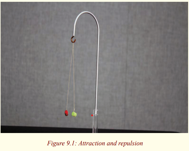
Procedure
1. Charge one lucite rod by rubbing it vigorously with silk. Place the
rod into the stirrup holder as shown in Figure.
2. Rub the second lucite rod with silk, and bring it close to the firstrod
3. What happens? Record the observations in your notes.
4. Rub the rough plastic rod with cat’s fur, and bring this rod near the
lucite rod in the stirrup. Record your observations.
5. What do you conclude?
6. Note down observation in your notebook.
For reference purposes, according to the convention originally chosen by
Benjamin Franklin, the lucite rods rubbed with silk become positively charged,
and the rough plastic rods rubbed with cat’s fur become negatively charged.Hard rubber rods, which are also commonly used, become negatively charged.
Coulomb’s law
Activity 2
Materials
* Coulomb’s Law apparatus
* Electrophorus (The electrophorus is a simple electrostatic induction
device. It’s an inexhaustible source of charge”).
* Silk cloth.* A computer for the graph and quick calculation.
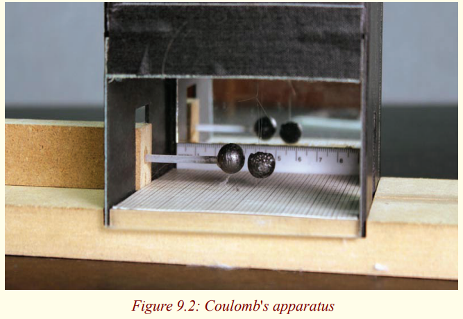
Procedure
1. Take a moment to check to position of the hanging ball in your
Coulomb apparatus. Look in through the side plastic window. The
hanging ball should be at the same height as the sliding ball (i.e.
the top of the mirrored scale should pass behind the centre of the
hanging pith ball, as in Figure 10.3 below). Lift off the top cover
and look down on the ball. The hanging ball should be centred on
a line with the sliding balls. If necessary, adjust carefully the finethreads that hold the hanging ball to position it properly.
2. Charge the metal plate of the electrophorus in the usual way by
rubbing the plastic base with silk, placing the metal plate on thebase, and touching it with your finger.
3. Lift off the metal plate by its insulating handle, and touch itcarefully to the ball on the left sliding block.
4. Slide the block into the Coulomb apparatus without touching the
sides of the box with the ball. Slide the block in until it is close to
the hanging ball. The hanging ball will be attracted by polarization,
as in Section III of this lab. After it touches the sliding ball, the
hanging ball will pick up half the charge and be repelled away.
Repeat the procedure if necessary, pushing the sliding ball up untilit touches the hanging ball.
5. Recharge the sliding ball so it produces the maximum force, and
experiment with pushing it towards the hanging ball. The hangingball should be repelled strongly.
6. You are going to measure the displacement of the hanging ball. You
do not need to measure the position of its centre, but will record
the position of its inside edge. Remove the sliding ball and record
the equilibrium position of its inside edge that faces the sliding
ball, which you will subtract from all the other measurements todetermine the displacement d.
7. Put the sliding ball in, and make trial measurements of the inside
edge of the sliding ball and the inside edge of the hanging ball. The
difference between these two measurements, plus the diameter of
one of the balls, is the distance r between their centres. Practice
taking measurements and compare your readings with those of your
lab partner until you are sure you can do them accurately. Try toestimate measurements to 0.2 mm.
8. Take measurements, and record the diameter of the balls (by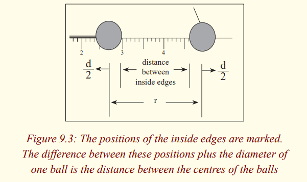
sighting on the scale).
9. Remove the sliding ball, and recheck the equilibrium position ofthe inside edge of the hanging ball.
10. You can record and graph data in Excel or by hand (although if
you work by hand, you will lose the opportunity for 2 mills of
additional credit below). Recharge the balls as in steps 1 – 4,
and record a series of measurements of the inside edges of the
balls. Move the sliding ball in steps of 0.5 cm for each newmeasurement.
11. Compute columns of displacements d (position of the hanging ball
minus the equilibrium position) and the separations r (difference
between the two recorded measurements plus the diameter of oneball).
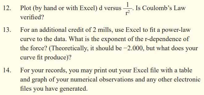
Knowledge of the forces that exist between charged particles is necessary for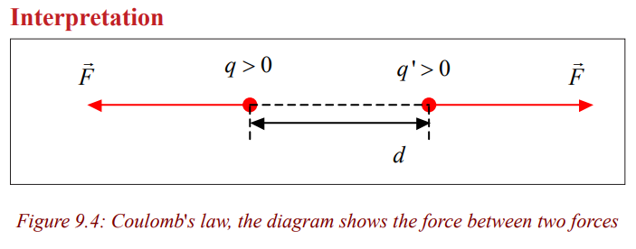
an understanding of the structure of the atom and of matter. The magnitude of
the forces between point charges was first investigated quantitatively in 1785by Coulomb, a French scientist. The law he discovered is stated as follows:
“The force between two point charges is directly proportional to the
product of charges divided by the square of their distance apart”.
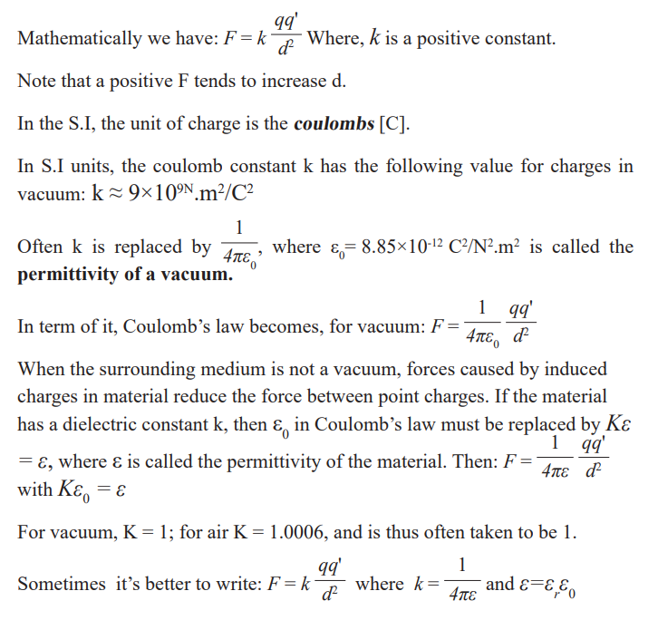
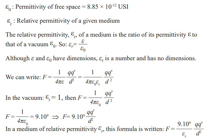
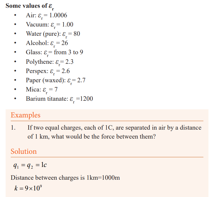
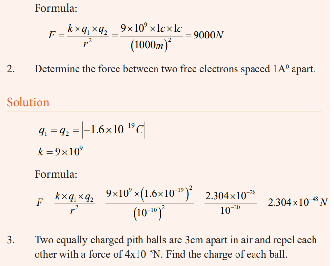
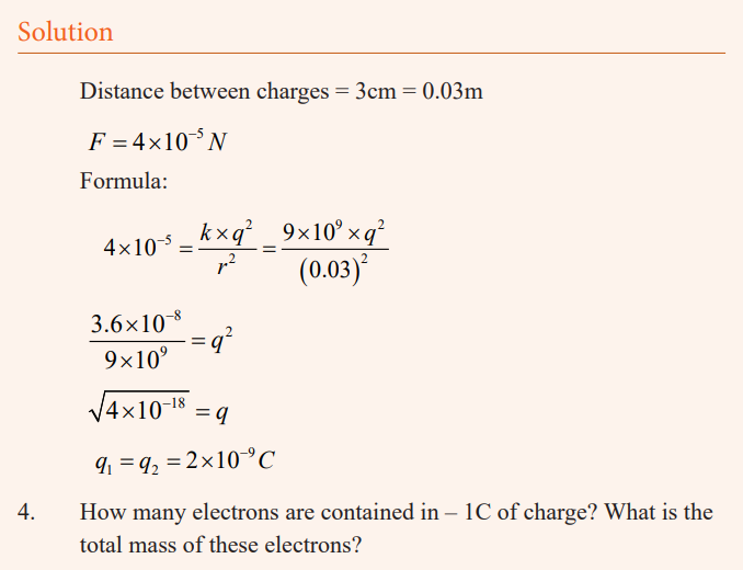
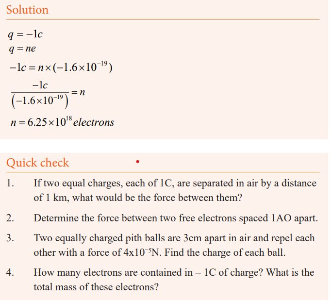
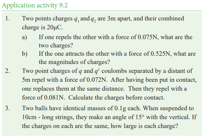
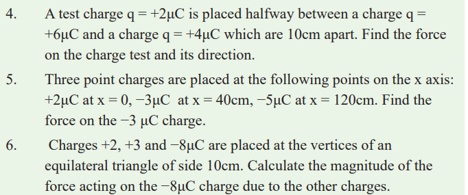
Electric field
Notions and definitions
Questions to think about
a) You have learned about Coulomb’s law and you have seen
that when an electric charge is brought near to another, there
is an attractive or a repulsive force. Does that force acts whencharges are in contact or it acts even at a certain distance?
b) If so, what can be the reason?
c) Does that force increase or decrease when the distancebetween charges increases?
After responding to those questions, you’ll see that around an electric charge
is a region so that when another charge is placed in it, it undergoes an electricforce. That region is called electric field created by the first charge.
An electric field can be defined as a region where an electric force is obtained.It’s a region where an electric charge experiences a force.
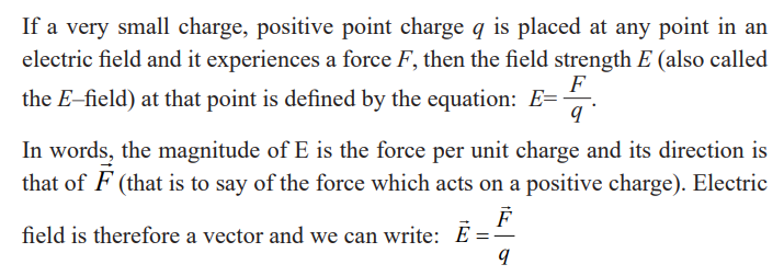
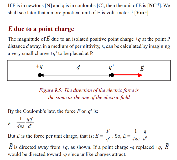
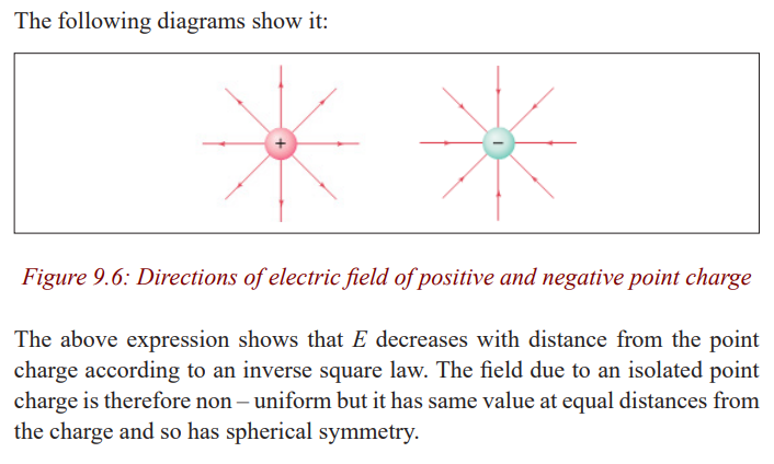
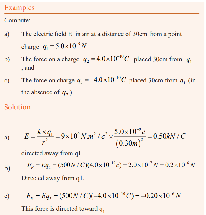
Field lines (lines of force)
Activity 4: Lab zone
Existence of field lines
This shows the shape of electric fields, in much the same way that magneticfields are demonstrated with iron filings.
Materials
* Power supply, EHT, 0-5kV. * Electric fields apparatus.* Semolina. * Castor oil.
Procedure
a) Fill the electrode unit with a layer of castor oil to a depth
of about 0.5cm. Sprinkle a thin layer of semolina over the
surface. (A thin piece of glass tubing drawn out to give a
fine pointed stirrer is helpful so that the semolina is evenly
distributed.) It is better to start with too little semolina than
to start with too much. You can always increase the quantitylater.
b) Place the electrodes in the castor oil. Connect the positive
and negative terminals of the EHT power supply to the
electrodes. Adjust the supply to give 3,000 to 4,000 volts.
When the voltage is switched on, the field lines will beclearly visible.
c) Try electrodes of different shapes. For example, one can be
a ‘point’ electrode whilst the other is a plate, or two point
electrodes can be used. A wire circular electrode with a
point electrode at the centre will show a radial field. The
field with two plates quite close together should also beshown.
A line of force or field lines is defined as a line such that the tangent to it at a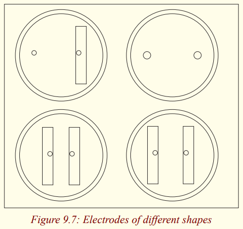
point is in the direction of force on a small positive charge placed the point.
Arrows on the lines of force show the direction of the force on a positivecharge; the force on a negative charge.
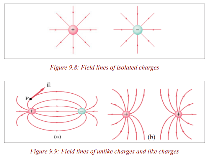
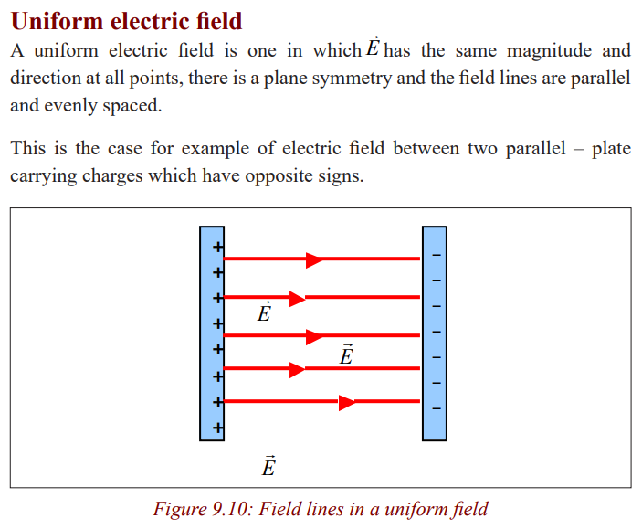
Electric field due to a distribution of electric charges
Activity 5
Electric field due to a distribution of charges
Materials
* A sheet of paper
* A pen* A ruler
Procedure
1. Represent a distribution of charges where you have charges of
different signs.
2. Represent a point A where you want to find the total electric field.
3. At the point, A represents directions of electric fields vectors
produced by each charge.
4. Do the sum of electric fields. Remember that an electric field is
a vector. When they make a certain angle between them, use the
method of parallelogram. When they have the same direction or
opposite directions, use the appropriate method.
5. Establish a mathematical relation of the total electric field due to thedistribution of charges.
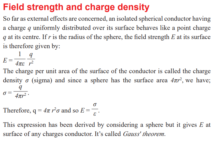
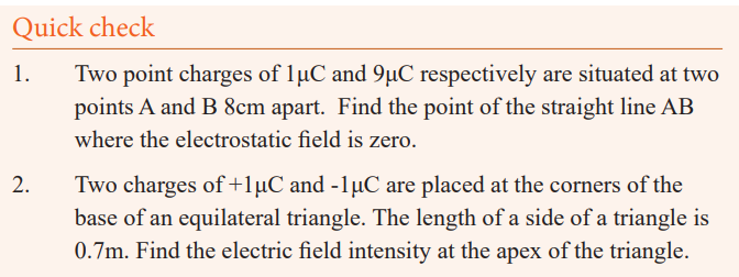
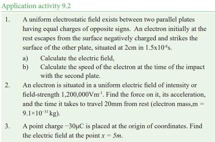
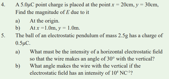
Potential difference
Work of electric force
Activity 6
Find the expression of the work done by an electric force
a) When can we say that we have a uniform electric field?
b) Draw a diagram showing two plates of opposite signs (the left
plate is positive and the right one is negative) between which the
electric field is uniform.
c) Show the direction of field lines in the electric field.
d) Between the two plates, put a positive charge at a point A which
has to travel toward a point B in the field.
e) Represent the direction of the vector force on the line joining A and B.
f) Write down the expression of the force undergone by the charge.
g) What is the expression of the work done if the charge has to move
from A to B (in the final formula)?
Particles that are free to move, if positively charged, normally tend towards
regions of lower voltage (net negative charge), while if negatively chargedthey tend to shift towards regions of higher voltage (net positive charge).
However, any movement of a positive charge into a region of higher voltage
requires external work to be done against the field of the electric force, work
equal to that electric field would do in moving that positive charge the same
distance in the opposite direction. Similarly, it requires positive external work
to transfer a negatively charged particle from a region of higher voltage to aregion of lower voltage.
The electric force is a conservative force: work done by a static electric field is
independent of the path taken by the charge. There is no change in the voltage
(electric potential) around any closed path; when returning to the startingpoint in a closed path, the net of the external work done is zero.
Potential in a field
Activity 7
Understanding the potential in a field
1. What kind of energy has a body when it’s held above the earth? If
the body has to move under the force of gravity, does it move froma point of great height to one of less or it’s the inverse?
2. Do you agree or not that points in the earth’s gravitational fieldhave potential values depending on their heights?
3. According to you, can this theory be similar to the one establishedfor electric field? Explain.
4. For charges, instead of saying gravitational potential for
gravitational field, can we say electric potential for the case ofelectric field? Explain.
5. Can points around the charge be said to have electric potential?
6. How can we define the electric potential at a point?
Potential generally refers to a currently unrealized ability. The term is used in
a wide variety of fields, from physics to the social sciences to indicate things
that are in a state where they are able to change in ways ranging from thesimple release of energy by objects to the realization of abilities in people.
Although the concept of electric potential is useful in understanding electrical
phenomena, only differences in potential energy are measurable. If an electric
field is defined as the force per unit charge, then by analogy an electric potential
can be thought of as the potential energy per unit charge. Therefore, the work
done in moving a unit charge from one point to another (e.g., within an electriccircuit) is equal to the difference in potential energies at each point.
Potential difference, work, energy of charges
Activity 8
Electric potential is a location-dependent quantity that expresses the amount
of potential energy per unit of charge at a specified location. When a Coulomb
of charge (or any given amount of charge) possesses a relatively large quantity
of potential energy at a given location, then that location is said to be a location
of high electric potential. And similarly, if a Coulomb of charge (or any given
amount of charge) possesses a relatively small quantity of potential energy
at a given location, then that location is said to be a location of low electric
potential. As we begin to apply our concepts of potential energy and electric
potential to circuits, we will begin to refer to the difference in electric potentialbetween two points.
Relation between E and V
Activity 9
Relation between E and V
1. What is the relation to find the work done by an electric force to
move a charge from A to B, knowing that the distance between A
and B is d?
2. What is the relation of the work using the potential difference?
3. Equalize the two relations and deduce the value of E. The relation
found is the one between E and V.
4. From the expression found, deduce the new unit of the electric field E.
5. Write down the relation between E and V found, express in
equation of V, write the electric field produced by a charge at a
point deduce the electric potential created by a charge at a pointsituated at a distance d from it.
The effect of any charge distribution can be described either in terms of
electric field or in terms of electric potential. Electric potential is often easier
to use since it is a scalar whereas electric field is a vector. There is an intimate
connection between the potential and the electric field. Let us consider the
case of a uniform electric field, such as that between the parallel plates (fig.)whose difference of potential is Vba.
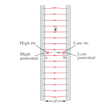

Examples
In figure below, the potential difference between the metal plates is 40v.
a) Which plate is at the higher potential?
b) How much work must be done to carry a +3.0C charge from B to
A? from A to B?
c) How do we know that the electric the electric field is in the
direction indicated?d) If the plate separation is 5.0mm. what is the magnitude of E?
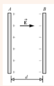
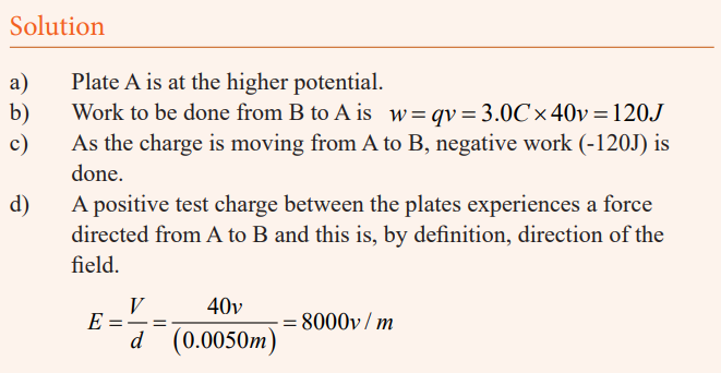
Motion of electric charges in an electric field
Activity 10
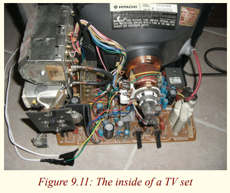
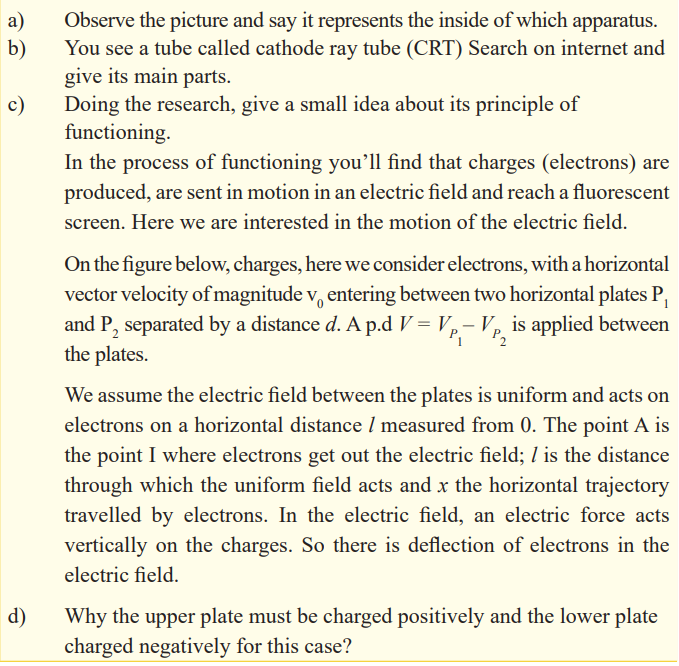
There are so many applications of cathode ray tube which is a practical example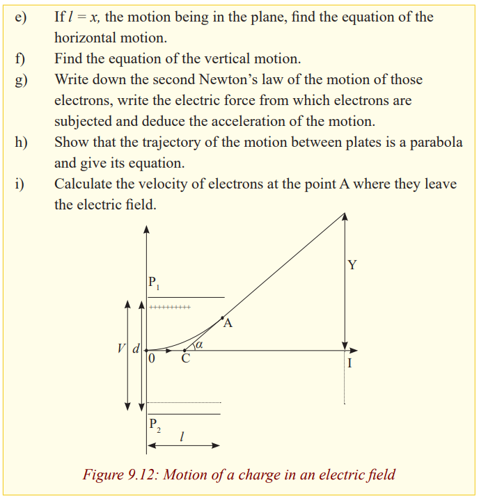
of the motion of electrons in an electric field in daily life. For example TVsets, oscilloscope, etc. use cathode ray tubes.
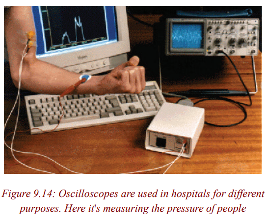
Lightening and lightening arrestor
Activity 11
Lightening and lightening arrestor
a) Surely, you have heard a thunder before the rainfall. What do
you observe in the sky during it?
b) According to you, this is due to what?
c) Is the fact observed dangerous?
d) If yes, do you know some consequences which you have
observed or heard?
e) If yes, is there a way to be protected from it?
f) Do some research on internet to know more about it andsubmit the result of your research to the teacher.
Some explanation
What you observe is called Lightening which is a sudden electrostatic
discharge (the sudden flow of electricity between two electrically charged
objects caused by contact, an electrical short, or dielectric breakdown) during
an electrical storm between electrically charged regions of a cloud (called intra-
cloud lightening or IC), between that cloud and another cloud (CC lightening),
or between a cloud and the ground (CG lightening). The charged regions in the
atmosphere temporarily equalise themselves through this discharge referred
to as a strike if it hits an object on the ground. Although lightening is always
accompanied by the sound of thunder, distant lightening may be seen but be
too far away for the thunder to be heard. Lightening strikes can be damagingto buildings and equipment, as well as dangerous to people.
Buildings often use a lightening protection or lightening rod system consisting
of a lightening rod (also called a lightening conductor) and metal cables to
divert and conduct the electrical charges safely into the ground. Another form
of lightening protection system creates a short circuit to prevent damage to
equipment. The electrically conducting metal skin of commercial aircraft isisolated from the interior of to protect passengers and equipment.
Often, the lightening protection is mounted on top of an elevated structure,
such as a building, a ship, or even a tree, electrically bonded using a wire
or electrical conductor to interface with ground or “earth” through an electrode,
engineered to protect the structure in the event of lightening strike. If lightening
hits the structure, it will preferentially strike the rod and be conducted to the
ground through the wire, instead of passing through the structure, where it
could start a fire or cause electrocution. Lightening rods are also called finials,air terminals or strike termination devices.
In a lightening protection system, a lightening rod is a single component of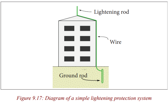
the system. The lightening rod requires a connection to earth to perform its
protective function. Lightening rods come in many different forms, including
hollow, solid, pointed, rounded, flat strips or even bristle brush-like. The main
attribute common to all lightening rods is that they are all made of conductive
materials, such as copper and aluminum. Copper and its alloys are the mostcommon materials used in lightening protection.
Unit 10 :Applications of thermodynamics laws
Key unit Competence
Evaluate the applications of first and second laws of thermodynamics in reallife.
Unit goals
By the end of this unit, I will be able to:
* differentiate between Internal energy and total energy of a system.
* explain the work done by the expanding gas.
* state the first law of thermodynamics.
* state the second law of thermodynamics.* explain thermodynamic processes in heat engines.
Introductory activity
Mutesi is a parent of two children at a certain school. Before she takes them
to school, she first makes sure that she prepares food and drinks for them
and packs some in flasks so that her children can eat and drink during lunchtime.
She then drives them to school before she reports to her working place and
then from the school she then diverts to her working place which is about 5km away from the school.
The parking yard at her work place is a plain place without any shade but
she makes sure that her car is parked near a tree that is near the parking yard
to prevent it from different damages among which is destruction of tyres ofthe car.
a) Explain why Mutesi makes use of flasks not normal utensils like metallicbowels while parking foods and drinks for her children.
b) Is there heat exchange inside the flasks? Explain your reasoning.
c) Imagine on a certain day these two children only eat food and leaves,
the drink in the flask and by mistake they forget flask in the store and
the mother come to pick it the next day. Do you think the contents in the
flask will be at the same temperatures? Explain all scientific phenomenathat may lead to either loss or gain in energy of the contents in the flask.
d) Explain why in most cases the outer covering of a flask is always made
of a poor conductor? Explain how quality and efficiency of these flaskscan be improved by manufactures.
e) Based on statements above, Mutesi normally parks her car under a shade
to prevent her car from being exposed to sunshine. Explain how duringhot days the tyres of a car may burst.
f) Her Car uses petrol in operation. During operation of her car, the engine
draws fuel (Petrol) air mixture from the tank into the engine, explain allthe processes that take place in the engine.
Introduction
Before, you learnt that:
• Heat is a form of energy.• Heat can be changed / transformed from one form to another.
So, if in a system heat changes from one form to another, its called thermaldynamic system.
The systems to discuss in this unit include refrigerators, heat pumps, car engines.
Remember that heat is the measure of total internal energy of a body. This meansthat particles of a body vibrate because of energy they have.
Thermal energy and internal energy
Activity 1
Have you ever boiled water on a sauce pan with a cover?Describe what happens to the cover when water boils?
When water boils, the vapour pushes the cover off the sauce pan. You have
already seen in your early secondary that heat is a form of energy. Therefore,
when this saucepan is heated, the heat gained is used to boil off the water and
extra work is done to push the sauce pan cover. This total heat energy suppliedis called thermal energy.
Science in action! Discover
• Explain why an inflated bicycle tube bursts when it is left on sunshine for
a very long time.
• Similarly explain why a balloon full of air bursts as it rises in the
atmosphere.• Note down your observation in your exercise books.
You already know the characteristics of the three states of matter that is; solids,
liquids and gases. In this unit, we shall be interested in studying the behaviourof molecules in matter.
When the bicycle tube is left exposed to sunshine, it gets heated and the
molecules in the gas gain energy and hence its kinetic energy increases. As
a result, they collide frequently with the walls of the tube and therefore exerthigh pressure on the walls and the tube bursts.
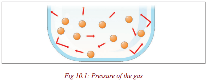
The same thing happens with the balloon in air.
The energy possessed by the molecules of the gas is called internal energy
of the gas. This energy depends on the temperature of the gas. When a gas is
heated its temperature increases and hence the average speed of molecules
also increases increasing the internal energy of the gas. Further increase of
heat supplied means that extra energy is absorbed by the molecules of the gas,hence expanding and pushing the tyre. As a result the tyre bursts.
The internal energy is defined as energy associated with random disorderedmotion of particles.
Activity 2
List down three utensils used for cooking food in your homes.
Describe how these utensils are used to cook the food. Are they always leftopen while cooking?
In all the above, there exists energy exchanges and such things are called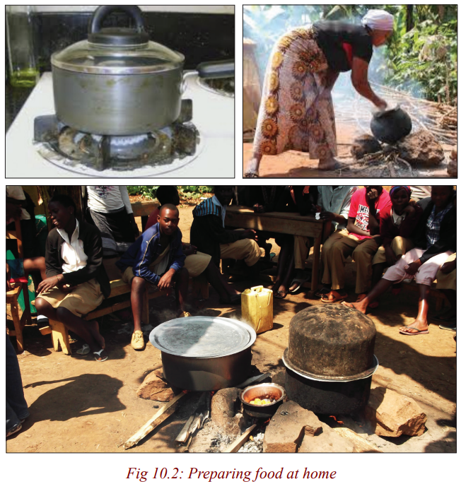
systems. Systems can either be closed or open. When water is being boiled in
an open sauce pan, vapour is allowed to escape. It is an example of an open
system. When someone cooks meat using a closed container, no gas is allowedto escape. Its an example of a closed system.
Whenever heat flows to or from a system, or work is done on or by a system,
there is a change in the energy of this system. The study of the processes thatcause these energy changes is termed thermodynamics.
Thermodynamic systems
Heat is the energy that flows by conduction, convection or radiation from
one body to another because of a temperature difference between them. These
bodies where exchange of heat to other forms of energy occurs are calledthermodynamic systems.
A thermodynamic system consists of a fixed mass of matter, often a gas,
separated from its surroundings, perhaps by a cylinder and a piston. For example
heat engines such as a petrol engine, a steam turbine and jet engine all contain
thermodynamic systems designed to convert heat into mechanical work. Head
pumps and refrigerators are thermodynamic devices for transferring heat froma cold body to a hotter one.
A thermodynamic system is any object or set of objects that we wish to
consider. Everything else in the universe we will refer to as its environment or
the surroundings. A system is separated from the remainder of the universe bya boundary. The boundary may be at rest or in motion.
A system can be homogeneous or heterogeneous. It can be gaseous, liquid or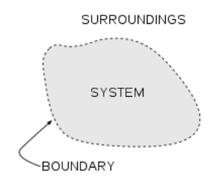
solid state. A system is in equilibrium when its properties do not change withtime.
A closed system is one for which no mass enters or leaves but may enter heat
exchanged with the environment. A closed system is sometimes referred to as
a control mass because the matter composing the system is assumed known
for all time. A closed system is said to be isolated if no energy in any formpasses across its boundaries, otherwise it is not isolated.
In an open system, mass may enter or leave as well as energy. An open system
is sometimes referred to as a control volume because the location composing
the system is assumed known for all time. The surface surrounding the control
volume is sometimes known as a control surface. The control surface can be
along a real surface of the system or it can be an imaginary surface chosen for
convenience. In general, a control mass can change shape and volume, but acontrol volume cannot.
In such devices, energy is transferred from one system to another by a forcemoving its point of application in its own direction.
The energy of a system, whether transferred to it as heat or work is termed asthe internal energy of the system.
When there is no heat transfer between two systems, that is, the two are at thesame temperature, they are said to be in thermal equilibrium.
Activity 3
Have you ever observed smoke moving in the atmosphere.
Move outside class and go towards the kitchen and observe how smoke is
moving. Describe briefly how it moves.Why does it move like that?
You have already seen in your early secondary that molecules in a gas are
more further apart and are always in constant random motion while moving at
high speed colliding with one another and the walls of the container, and whenthe gas is heated their speed increases.
Smoke particles are always in random motion and when they are moving in
air, they collide with air molecules and a zigzag pattern is seen.
Similarly, when smoke is put in a container and then closed, the particles areseen to be in a random motion. Smoke is an example of a real gas.
In thermodynamics, we are mainly interested in ideal gas. At highertemperatures, a real gas behaves like an ideal gas.
Activity 4
Have you ever heard of an ideal gas?What are the differences between a real gas and an ideal gas?
When a gas is heated, molecules move further apart and the forces of attractionsbetween them become negligible and the gas becomes ideal.
When the molecules become further apart, the gas expands and the volume of
the individual molecule becomes so small compared to the entire volume of
the gas. It therefore becomes negligible compared to the volume of the gas andthe gas becomes ideal.
When the molecules are colliding with one another, collisions are assumed to
be perfectly elastic. In this case, the gas becomes ideal because for a real gaswe expect to have time between approach and separation during collision.
Work done by an expanding gas
Activity 5: Discover
Explain why a pump gets hot when one pumps air into a tyre.
When you compress air in a bicycle pump, your muscles transfer energy
to the handle, which in turn transfers energy to the molecules of air in the
pump. This additional energy makes the molecules move faster. As they are
compressed into a smaller space, they also collide more often with the wall ofthe pump, so they transfer more energy to the metal wall and it becomes hot.
We have already seen how heat can be transferred, so you probably have a
good idea what Q means. Work is simply a force Multiplied by distance in thedirection of force.
A gas can be heated by compressing it, for example with a bicycle pump.
Hence the temperature of the gas can be raised either by doing work in
compressing it or by heating it. Likewise the temperature can be lowered byeither making the gas do work in expanding or by extracting heat from it.
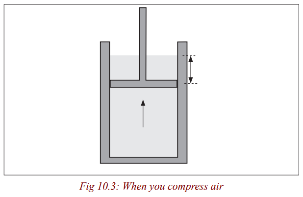
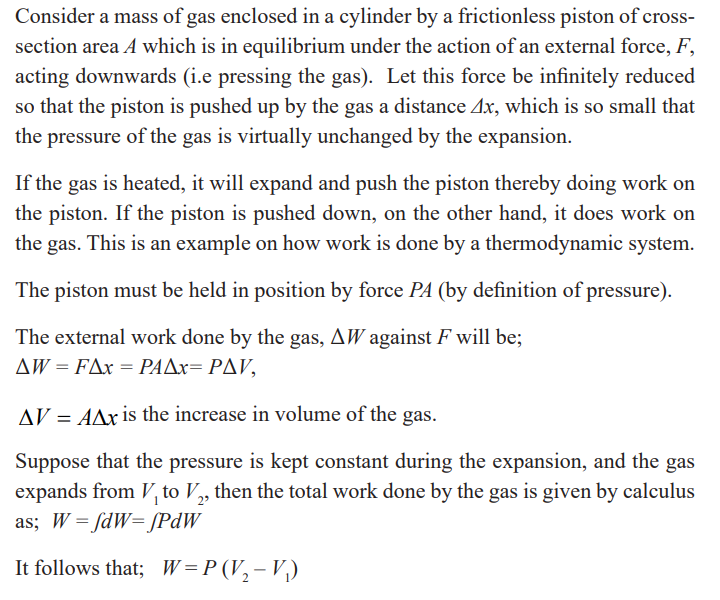
Example
Steam to drive an old-fashioned steam locomotive is supplied at a constant
gauge pressure of 1.75×10⁶N/m2 about 250 psi) to a piston with a 0.200-m radius.
Find the work done by the steam when the piston moves 0.800 m.
Solution
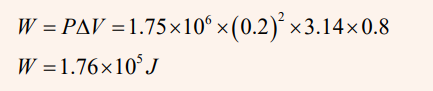
Specific heat capacities of gases
Gases are considered to have a number of specific heat capacities. A change in
temperature of a gas is likely to cause large changes in pressure and volume ofthe gas but for solids or liquids, the change in pressure is neglected.
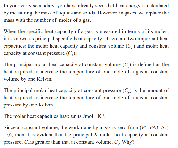
The reason as to why this is so can be done by considering cylinders in (a) and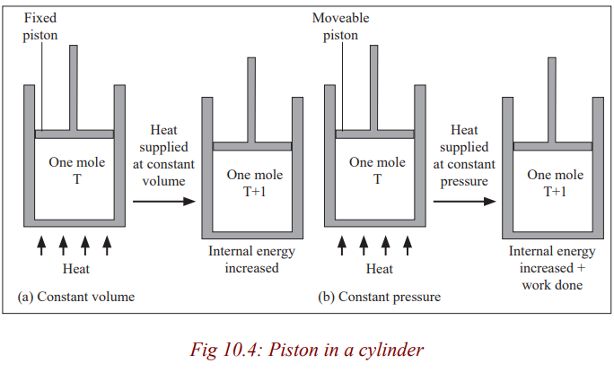
(b) each initially containing one mole of gas at temperature T and pressure,
P. The piston in (a) is fixed and that in (b) is frictionless and can move freely
but has a constant force applied to it. If heat is supplied to each until the
temperature has risen by one Kelvin, the increase of internal energy must bethe same in each case (Since the temperature rise is the same).
All the heat supplied in case (a) is used to increase the internal energy of the
gas. In (b), however, the gas expands and work is done by it on the piston; the
heat supplied in this case equals the increase of internal energy plus the workdone in the expansion of the gas.
Application activity 10.1
1. Which statement best describes the concept of a system?
A.the subject of the analysis C. a fluid-solid mixture
B.an object with fixed set of molecules D. an object that radiates heatinto its environment
2. Consider a refrigerator in a kitchen. Take the refrigerator and everything
in it to be our system. Which best describes the system's surroundings?
A.All of the air in the kitchen. C. The air inside the refrigerator
B.Any one standing in the kitchen. D. Everything in the universeexternal to the system.
3. Consider a refrigerator in a kitchen. Take the refrigerator and everything
in it to be our system. Which best describes the system's boundary?
A.All of the air in the kitchen.
B.The thin region separating the system from everything else.
C.The air inside the refrigerator.D.The outer walls of the refrigerator.
4. Which of the following statements are true?
A.A closed system is necessarily an isolated system
B.An isolated system is necessarily a closed system
C.A system cannot be both closed and isolated.
D.The concepts of closed and isolated in regards to a system are independentconcepts.
5. True or False: A system is in steady state if its properties are independentof time.
The first law of the thermodynamics
The first law of thermodynamics states that” in a closed system the energy
is conserved in any transfer of energy from one form to another. Means that
the change in internal energy of a system is equal to the heat added to the
system minus the work done by the system” this law is known as the law ofenergy conservation.
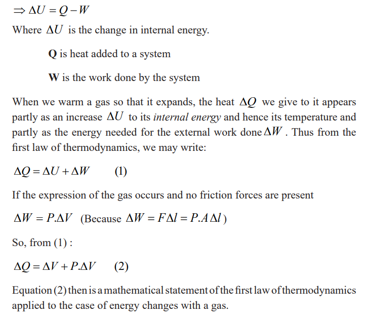
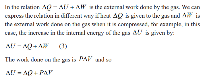
Example
Compute the internal energy change and temperature change for the twoprocesses involving 1 mole of an ideal monatomic gas.
a) 1500 J of heat are added to the gas and the gas does no work andno work is done on the gas
b) 1500 J of work are done on the gas and the gas does no work andno heat is added or taken away from the gas
Solution
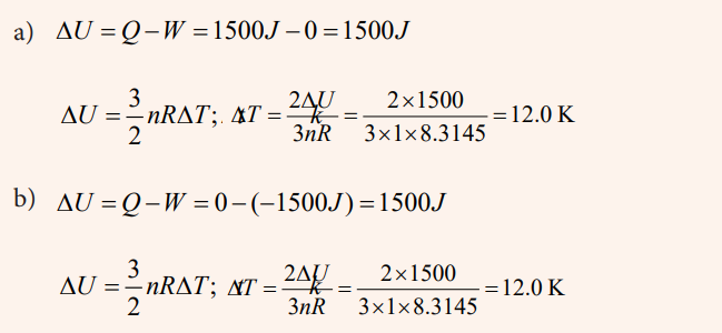
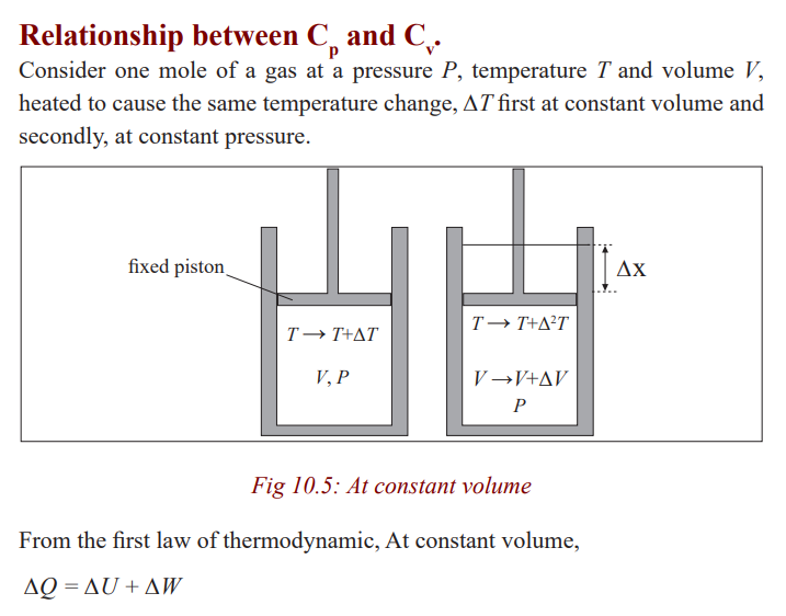
Applications of first law of thermodynamics in particular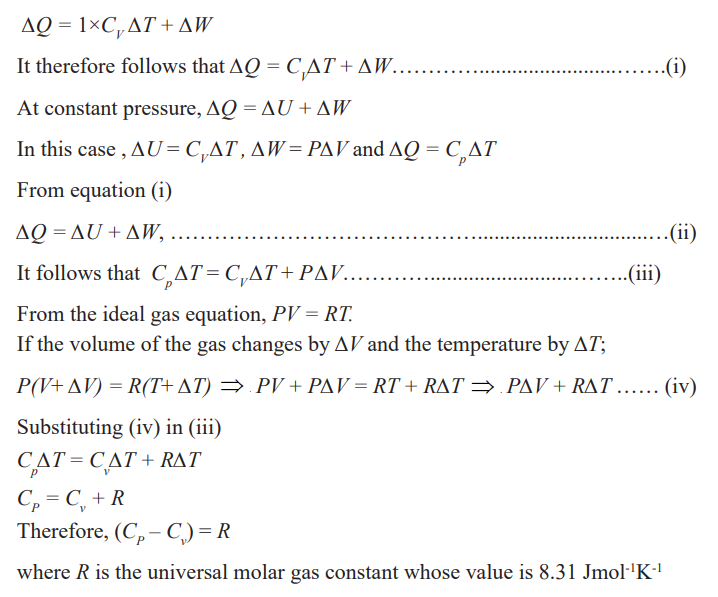
gas changes
The first law of thermodynamics that we discussed relates the changes in
internal energy of a system to transfers of energy by work or heat. In this case,
we consider applications of the first law in processes through which a gas istaken as a model.
Isovolumetric process (Isochoric process)
Activity 6
(i) Have you ever heard of an isovolumetric or isochoric process?Study the Figure and answer questions that follow;
(ii) What substance is likely to be getting cooked using the can on the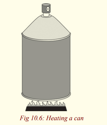
left? Give a reason for your answer.
(iii) Why is the can covered and not open?
(iv) If one tried to open it while its on fire, what do you think wouldhappen?
A process that takes place at constant volume is called an isovolumetricprocess.
From the figure 10.7, process AB takes place at a constant volume (volume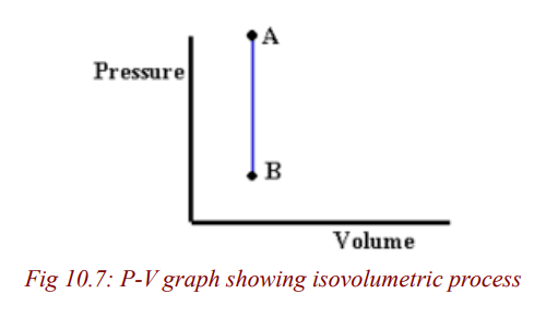
doesn’t change).
In such a process, the value of the work done is zero because the volume doesnot change. Hence, from the first law we see that in an isovolumetric process,
W = 0 and ΔU = Q (isovolumetric process)
Note:
• This expression specifies that if energy is added by heat to a system
at constant volume, then all of the transferred energy remains in thesystem as an increase in its internal energy.
• For example, when a can of spray paint is thrown into a fire, energy
enters the system (the gas in the can) by heat through the metal walls
of the can. Consequently, the temperature, and thus the pressure inthe can increases until the can possibly explodes.
Isobaric process
Activity 7
Boiling liquids in open containers is very safe for example if the container is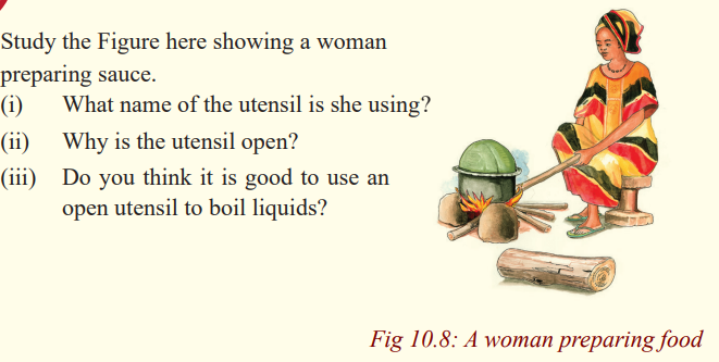
closed, pressure may build up in the container and force it to burst. Boiling in
open containers imply that the pressure of the substance is kept constant. This
process is called an isobaric process. An isobaric process is the one that occursat constant pressure.
Heating of water in an open vessel and the expansion of a gas in a cylinder
with a freely moving piston are typical examples of isobaric processes. In both
cases, the pressure is equal to atmospheric pressure. For example when water
is being heated, its volume increases and the pressure inside the container is
constant since the number of collisions between water molecules and the wallsof the container is constant.
The same process occurs when a gas enclosed in a cylinder with a frictionless
piston is heated such that at any time, the gas pressure equals the externalpressure.
In this process, the energy supplied is used to increase the internal energy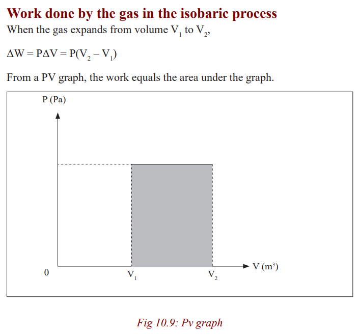
since the internal energy is independent of the volume.
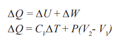
Isothermal change (constant temperature)
Activity 8
(i) Get a polythene bag and fill it with air.
(ii) Insert a thermometre in the bag and place it in the ice-water mixture.
(iii) Note what happens.
Do you notice that the gas condenses and the volume decreases?
What happens to the temperature recorded by the thermometer?
You can notice that the temperature remains constant. This change is calledCondensation and is an example of isothermal process.
Do you think this process is reversible?
An isothermal change can be reversible. An isothermal change is the change
that occurs at constant temperature. It is either a compression or expansion ofa gas at a constant temperature.
If the volume increases, the pressure must decrease and if the volumedecreases, the pressure must increase
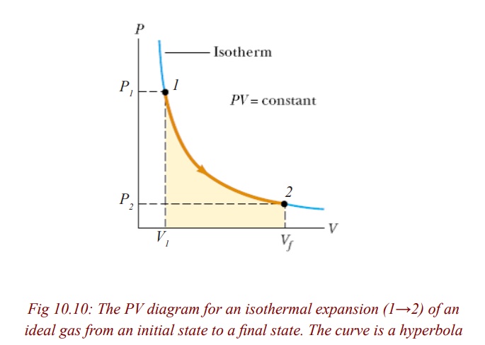
Conditions necessary for an isothermal process to occur
Activity 9: Discover
(i) On a cold day, how do you keep yourself warm?
(ii) In groups of five, describe how you can keep the temperature of thesystem constant.
For an isothermal process to take place, the gas must be contained in a thin
–walled heat conducting vessel/container in good thermal contact with aconstant temperature.
The process must be carried out slowly to allow time for heat exchange to takeplace.
Work done in Isothermal Change
Activity 10: Science at work
(i) Have you ever tried to boil water in a closed sauce pan?
(ii) What happens to the cover when the vapour starts to come off the water?
(iii) Notice that this vapour pushes the cover off the pan.
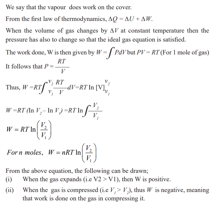
Comment.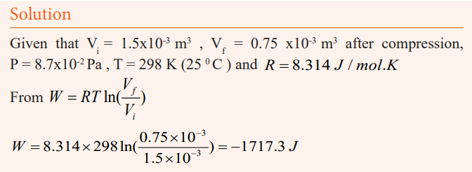
The answer has a negative value. This shows that the work is doneon to the gas (compressed).
Adiabatic change
Activity 11
(i) Pump a bicycle tyre using a pump until it is full.
(ii) Open the tube slowly while placing your other hand in its path.
(iii) Do you notice that the the air coming out of the tyre is hotter thanthe surrounding air?
As one pumps, the air molecules are compressed into a smaller space. They
also collide more often with the wall of the pump, so they transfer more energy
to one another and become hot. No heat has been supplied to the system. It iscalled an adiabatic compression.
Activity:12
(i) Now pump the tyre and leave it standing for sometime.
(ii) Make sure you don’t expose it to sun shine.
(iii) Open the valve after two hours while your hand is placed in the pathof air from it.
Do you notice that the air is colder than its surrounding?
Heat has been lost but not to the surroundings. When the air is left standing,
expansion occurs. This is associated with a decrease in temperature. It is calledan adiabatic expansion.
An adiabatic change is process in which no heat enters or leaves the gassystem. It is either an expansion or a compression.
If the gas expands, it does work, its internal energy is reduced and hence the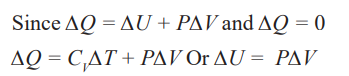
temperature is lowered.
If the gas is compressed, work is done on the gas, its internal energy willincrease and therefore its temperature rises.
Conditions that are necessary for an adiabatic change to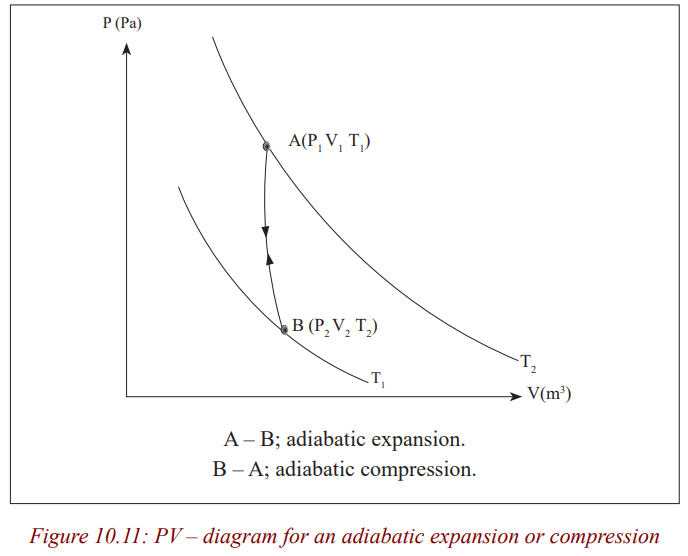
occur
Activity 13
How do you always protect yourself from a bad weather?
On a cold day, we always wear woolen jackets to protect ourselves from
coldness. Therefore no heat is either lost to the surrounding and or gained. Inthis case, an adiabatic process is achieved.
For an adiabatic process to be achieved, the gas must be contained in a thick–walled and perfectly insulated isolated container.
The process must be carried out rapidly to avoid any possible heat exchangesbetween the gas system and the surroundings.
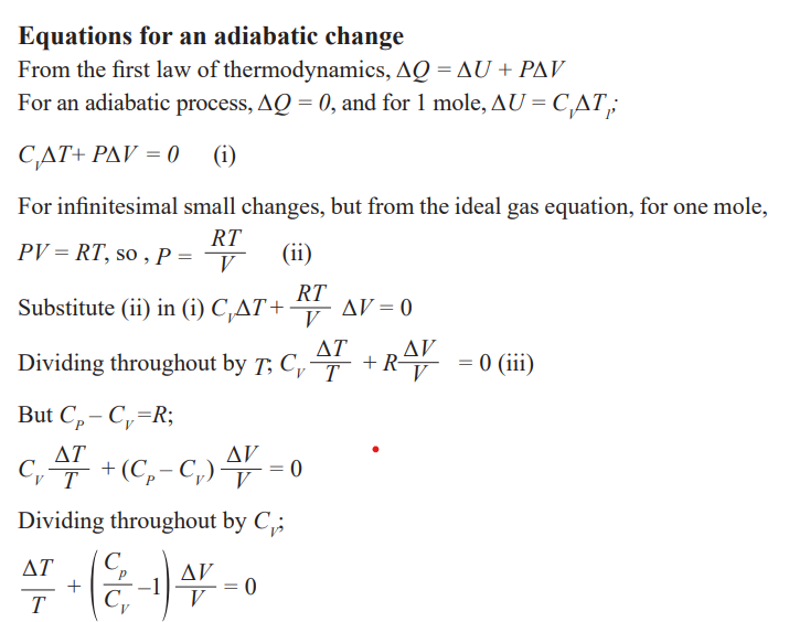
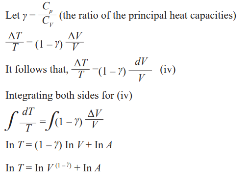
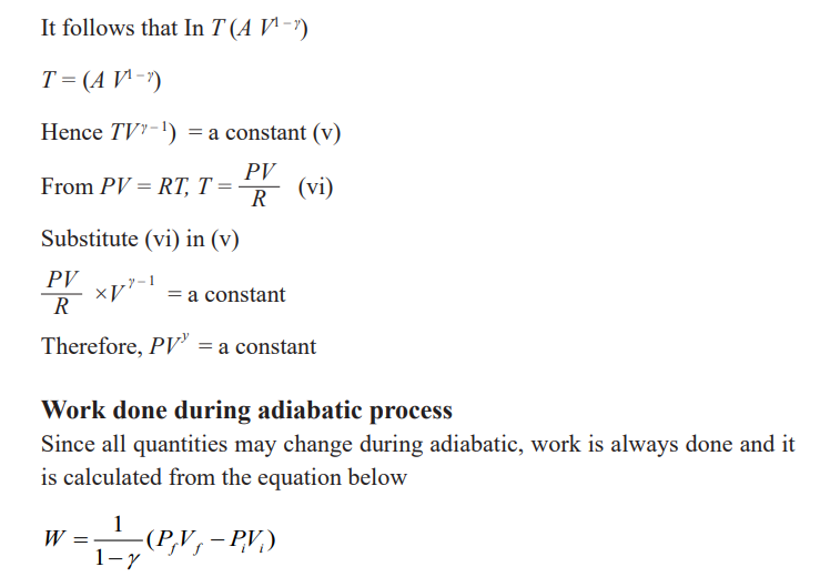
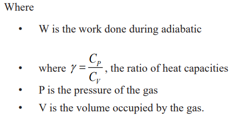
Activity 14
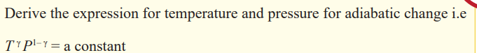
Example I
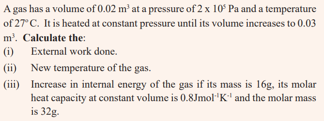
Solution
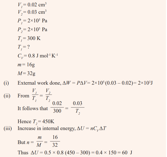
Example 2
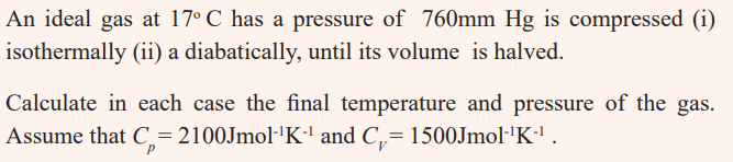
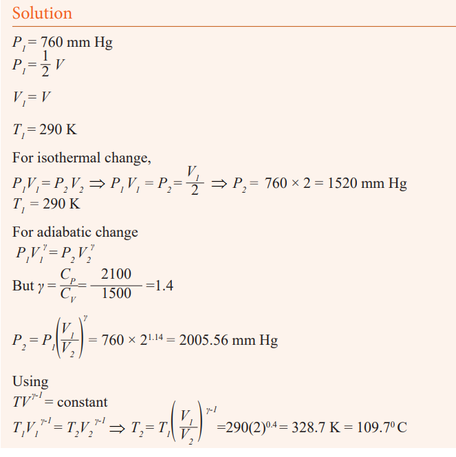
Application activity 10.2
1. A total of 135 J of work is done on a gaseous refrigerant as it undergoes
compression. If the internal energy of the gas increases by 114 J during
the process, what is the total amount of energy transferred by heat? Hasenergy been added or removed from the refrigerant by heat?
2. The internal energy of a system is initially 27 J. A total of 33 J of energy
is added to the system by heat while the system does 26 J of work. Whatis the system’s final internal energy?
3. Heat of 90 cal is supplied to a system and it is observed that no work isdone. Calculate the change in internal energy of this system.
4. One mole of an ideal gas at 250 C is allowed to expand reversibly at
constant temperature from a volume of 10 L to 20 L; calculate the workdone by the gas in joules.
5. A certain volume of dry air at N.T.P is expanded reversibly to three times
its volume
a) isothermally,b) adiabatically.
Calculate the final temperature in each case, assuming ideal behaviour.γ =1.40
Second Law of thermodynamics
Since the first law of thermodynamics states that energy is conserved. There
are, however, many processes we can imagine that conserve energy but are not
observed to occur in nature. Lets consider an example below of the first law tointroduce the second law.
For example, when a hot object is placed in contact with a cold object, heat
flows from the hotter one to the colder one, never spontaneously the reverse.
If heat were to leave the colder object and pass to the hotter one, energy couldstill be conserved. Yet it doesn’t happen spontaneously the reverse.
There are many other examples of processes that occur in nature but whose
reverse does not. To explain this lack of reversibility, scientists in the latter
half of the nineteenth century formulated a new principle known as the secondlaw of thermodynamics.
The second law of thermodynamics is a statement about which processes
occur in nature and which do not. It can be stated in a variety of ways, all of
which are equivalent. One statement is that: “Heat can flow spontaneously
from a hot object to cold object; heat will not flow spontaneously from acold object to a hot object.”
The development of a general statement of the second law of thermodynamics
was based partly on the study of heat engines. A heat engine is any device
that changes thermal energy into mechanical work, such as steam engines andautomobile engines.
Applications of the second law of thermodynamics
Heat engines
Activity 15
* Have you ever heard of an engine?
* Where exactly do we find engines?
* What do you think an engine is?
* How do you think the engine operates?
Any device that transforms heat into work or mechanical energy is called
heat engine. All heat engines absorb heat from a source at high temperature,perform some mechanical work, and discard heat at a lower temperature.
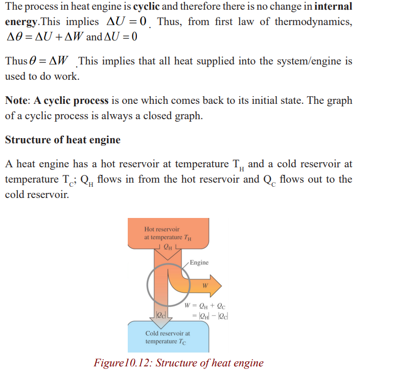
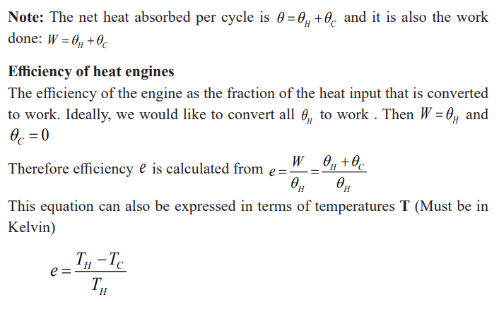
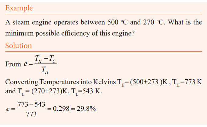
Impact of heat engines on climate
Most of air pollution is caused by the burning of fuels such as oil, natural gas
etc. The air pollution has an adverse effect on the climate. Climate change is
the greatest environmental threat of our time endangering our health. When
a heat engine is running, several different types of gases and particles areemitted that can have detrimental effects on the environment.
Of concern to the environment are carbon dioxide, a greenhouse gas; and
hydrocarbons. Engines emit greenhouse gases, such as carbon dioxide, which
contribute to global warming. Fuels used in heat engines contain carbon. Thecarbon burns in air to form carbon dioxide.
The Carbon dioxide and other global warming pollutants collect in the
atmosphere and act like a thickening blanket and destroy the ozone layer.
Therefore, the sun’s heat from the sun is received direct on the earth surfaceand causes the planet to warm up.
As a result of global warming, the vegetation is destroyed, ice melts and water
tables are reduced. Heat engines especially diesel engines produce Soot whichcontributes to global warming and its influence on climate.
The findings show that soot, also called black carbon, has a warming effect.
It contains black carbon particles which affect atmospheric temperatures in a
variety of ways. The dark particles absorb incoming and scattered heat from
the sun; they can promote the formation of clouds that can have either cooling
or warming impact. Therefore soot emissions have significant impact onclimate change.
Similarly, some engines leak, for example, old car engines and oil spills all
over. When it rains, this oil is transported by rain water to lakes and rivers.
The oils then create a layer on top of the water and prevent free evaporationof the water.
Carnot cycle and Carnot engine
In 1824 a French engineer named Sadi Carnot described a theoretical engine,
now called a Carnot engine, which is of great importance from both practical
and theoretical viewpoints. He showed that a heat engine operating in an ideal,
reversible cycle—called a Carnot cycle—between two energy reservoirs isthe most efficient engine possible.
An ideal engine establishes an upper limit on the efficiencies of all other
engines. That is, the net work done by a working substance taken through the
Carnot cycle is the greatest amount of work possible for a given amount ofenergy supplied to the substance at the higher temperature.
Carnot’s theorem can be stated that no real heat engine operating between
two energy reservoirs can be more efficient than a Carnot engine operatingbetween the same two reservoirs.
Note: No Carnot engine actually exists, but as a theoretical idea it played animportant role in the development of thermodynamics.
The idealized Carnot engine consisted of four processes done in a cycle, two
of which are adiabatic (Q = 0) and two are isothermal (ΔT = 0). This idealizedcycle is shown in figure 1.8.
Each of the processes was considered to be done reversibly. That is, each of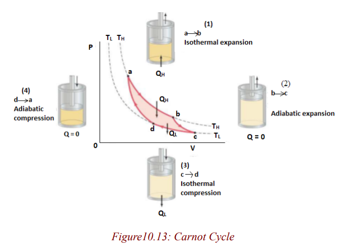
the processes (say, during expansion of the gases against a piston) was done so
slowly that the process could be considered a series of equilibrium states, and
the whole process could be done in reverse with no change in the magnitudeof work done or heat exchanged.
A real process, on the other hand, would occur more quickly; there would
be turbulence in the gas, friction would be present, and so on. Because of
these factors, a real process cannot be done precisely in reverse, the turbulence
would be different, and the heat lost to friction would not reverse itself. Thus
real processes are irreversible.
In the Carnot cycle, heat engines work in a cycle, and the cycle for the Carnotengine begins at point a on the PV diagram.
Note:
• The gas is first expanded isothermally, with addition of heat QH,along the path ab at temperature TH.
The equation above gives a Carnot (ideal) efficiency. It expresses the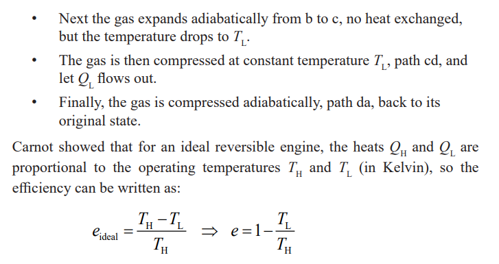
fundamental upper limit to the efficiency. Real engines always have an
efficiency lower than this because of losses due to friction. Real engines
that are well designed reach 60 to 80% of the Carnot efficiency.Otto Cycle and Diesel Cycle
Otto Cycle
An Otto cycle is an idealized thermodynamic cycle which describes the
functioning of a typical spark ignition reciprocating piston engine, thethermodynamic cycle most commonly found in automobile engine.
The Pressure Volume diagram above represents the Otto cycle which has the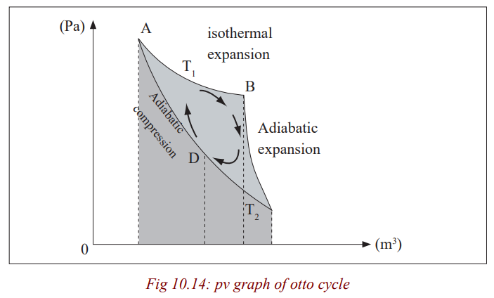
following strokes; the intake (A) stroke is performed by an isobaric expansion,
followed by an adiabatic compression (B) stroke (along 1-2). Through the
combustion of fuel, heat is added in an isovolumetric process (2-3), followed
by an adiabatic expansion process ( 3-4), characterising the power (C) stroke.
The cycle is closed by the exhaust (D) stroke, characterized by isovolumetriccooling and isobaric compression processes.
The processes are described by:
Process 1-2 is an isentropic compression of the air as the piston moves frombottom dead centre (BDC) to top dead centre (TDC).
Process 2-3 is a constant –volume heat transfer to the air from an external
source while the piston is at top dead centre. This process is
intended to represent the ignition of the fuel –air mixture andthe subsequent rapid burning.
Process 3-4 is an isentropic expansion (power stroke).
Process 4-1 completes the cycle by a constant-volume process in which heat isrejected from the air while the piston is a bottom dead centre.
The Otto cycle consists of adiabatic compression, heat addition at constant
volume, adiabatic expansion, and rejection of heat at constant volume. In the
case of a four-stroke Otto cycle, technically there are two additional processes;
one for the exhaust of waste heat and combustion products (by isobaric
compression), and one for the intake of cool oxygen –rich) air (by isobaric
expansion); however, these are often omitted in a simplified analysis. Even
though these two processes are critical to the functioning of a real engine,
wherein the details of heat transfer and combustion chemistry are relevant,
for the simplified analysis of the thermodynamic cycle, it is simpler and more
convenient to assume that all of the waste-heat is removed during a singlevolume change.
Diesel Cycle
The diesel cycle is the thermodynamic cycle, which approximates the pressure
and volume of the combustion chamber of the Diesel engine, invented by
Rudolph Diesel in 1897. It is assumed to have constant pressure during the
first part of the “combustion” phase V2 to V2
in the diagram, below). This is an idealised mathematical model;
real physical diesels do have an increase in
pressure during this period, but it is less pronounced than in the Otto cycle.
The idealized Otto cycle of a gasoline engine approximates constant volumeduring that phase, generating more of a spike in a P-V diagram.
The Idealised Diesel Cycle
From P-V diagram for the Ideal Diesel cycle, the cycle follows the numbers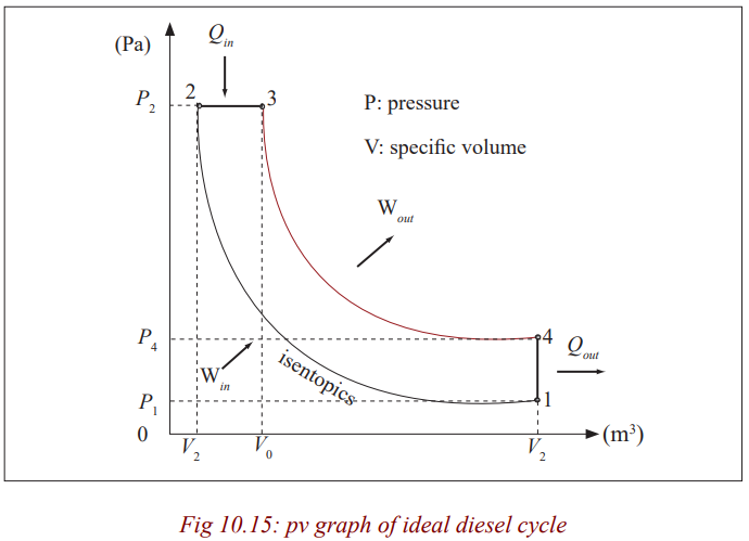
1-4 in clockwise direction.
The image on the top shows a P-V diagram for the ideal Diesel cycle; where
P is pressure and V is specific volume. The ideal Diesel cycle follows the
following four distinct processes (the colour references refers to the colour ofthe line on the diagram):
Process 1-2 is isentropic (adiabatic) compression of the fluid (blue colour).
Process 2-3 is reversible (isobaric constant pressure heating (red).
Process 3-4 is isentropic (adiabatic) expansion (yellow).
Process 4-1 is reversible constant volume cooling (green).
The Diesel is a heat engine; it converts heat into work. The isentropic processes
are impermeable to heat; heat flows into the loop through the left expanding
isobaric process and some of it flows back out through the right depressurisingprocess, and the heat that remains does the work.
Work in (Win) is done by the piston compressing the working fluid.
Heat in (Qin) is done by the combustion of the fuel.
Work out (Wout) is done by the working fluid expanding on to the piston (thisproduces usable torque).
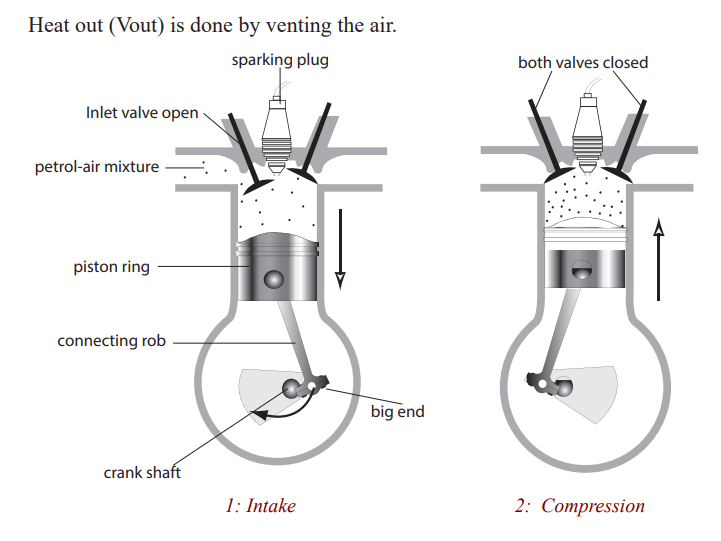
A heat engine is a machine, which changes heat energy, obtained by burning a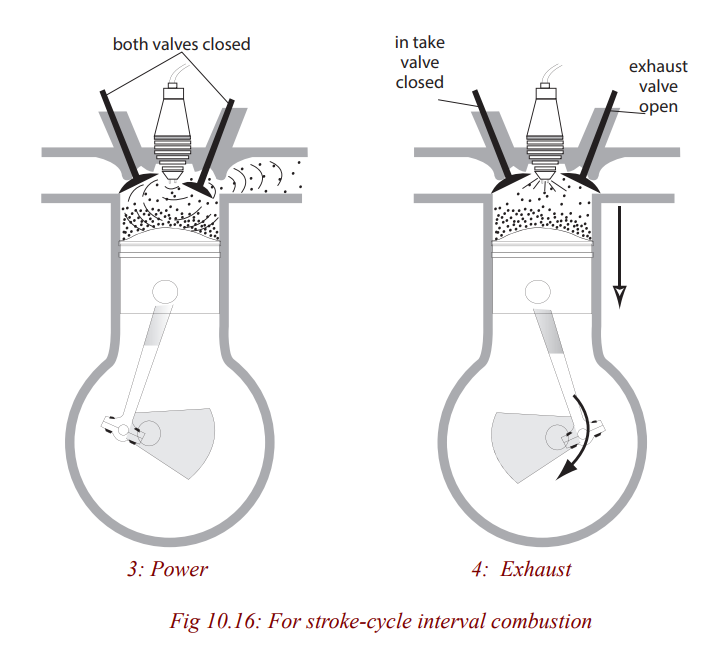
fuel, to kinetic energy. In an internal combustion engine, e.g petrol, diesel, jet
engine, the fuel is burnt in the cylinder of chamber where the energy changeoccurs. This is not so in other engines e.g steam turbine.
Petrol engine
Activity 16
(i) How many types of fuels do vehicles use to operate?
(ii) Have you ever heard of vehicles which use petrol in order to operate?
(iii) List down four vehicles which use petrol.
(iv) What type of engine do they have?
Many vehicles use petrol in order to move. Such vehicles are small cars and
motorcycles. The engine they have is called a petrol engine since it uses petrol
to operate. It operates by moving the piston. The upward and downwardmovement of the piston is called a stroke.
a) Four – stroke engine: On the intake stroke, the piston moves
down (due to the starter motor in a car or the kick start in a
motor cycle turning the crankshaft) so reducing the pressure
inside the cylinder. The inlet value opens and the petrol – air
mixture from the carburetor is forced into the cylinder byatmospheric pressure.
On the compression stroke, both valves are closed and the pistonmoves up, compressing the mixture.
On the power stroke, a spark jumps across the points of thesparking plug and explodes the mixture, forcing the piston down.
On the exhaust stroke, the outlet valve opens and the piston rises,pushing the exhaust gases out of the cylinder.
The crankshaft turns a flywheel (a heavy wheel) whosemomentum keeps the piston moving between power strokes.
Most cars have atleast four cylinders on the same crankshaft.
Each cylinder fires in turn in the order 1-3-4-2, giving a powerstroke every half revolution of the crankshaft. Smoother running results.
b) Two-stroke engine: This is used in mopeds, lawnmovers and
small boats. Valves are replaced by ports on the side of thecylinder which are opened and closed by the piston as it moves.
Diesel engine
Activity 17
(i) Have you ever heard of vehicles which use diesel in order to move?
(ii) What kind of vehicles are they?
(iii) What is the name of the engine in such vehicles?
The engine which uses diesel is called a diesel engine. A diesel engine canoperate by making two or more strokes.
The operation of two and four stroke diesel engines is similar to that of the
petrol varieties. However, fuel oils is used instead of petrol, there is nosparking plug and the carburetor is replaced by a fuel injector.
Air is drawn into the cylinder on the down stroke of the piston and on the
upstroke it is compressed to about one-sixteenth of its original volume (which
is twice the compression in a petrol engine). This very high compression
increases the temperature of the air considerably and when, at the end of the
compression stroke, fuel is pumped into the cylinder by the fuel injector, it
ignites automatically. The resulting explosion drives the piston down on its
power stroke. (You may have noticed that the air in a bicycle pump gets hotwhen it is squeezed. The same applies here.)
Activity: 18
State the advantages of a diesel engine over a petrol engine.
Diesel engines, sometimes called compression ignition (C.I) engines, though
heavier than petrol engines, are reliable and economical. Their efficiency of
about 40% is higher than that of any other heat engine. A disadvantage of the
diesel engine is that its higher compression ratio means that it needs to bemore robust, and is therefore more massive.
The Refrigerator
Activity: 19
* How many of you have seen a
refrigerator?
* With the help of a teacher visit any
place where there is a refrigeration
and observe it carefully.
* How useful is it to our daily lives?
* Who can describe how it works?
* Write your suggestions in thenotebook.
A refrigerator is a device used to cool substances. It cools things by evaporation
of a volatile liquid called Freon. The coiled pipe around the freezer at the top
contains Freon which evaporates and takes latent heat from the surroundings
so causing cooling. The electrically driven pump removes the vapor and
forces it into the heat exchanger (pipes with cooling fins outside the rear ofthe refrigerator).
Here the vapor is compressed and liquefies (condenses) giving out latent heat
of vaporization to the surrounding air. The liquid returns to the coils around
the freezer and the cycle is repeated. An adjustable thermostat switches the
pump on and off, controlling the rate of evaporation and so the temperature ofthe refrigerator.
The operating principle of refrigerators is just the reverse of a heat engine. Eachoperates to transfer heat out of a cool environment into warm environment.
By doing work W, heat is taken from a low-temperature region, QL (such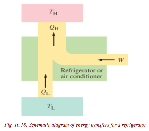
as inside a refrigerator), and a greater amount of heat is exhausted at a high
temperature, QH (the room). You can often feel this heat blowing out beneatha refrigerator.
A perfect refrigerator is the one in which no work is required to take heat from
the low-temperature region to the high temperature region is not possible.
This is Clausius statement of the second law of thermodynamics, alreadymentioned can be stated formally as:
“No device is possible whose sole effect is to transfer heat from one systemat a temperature TL into a second system at a higher temperature TH”.
To make heat flow from a low-temperature object (or system) to one at a highertemperature, work must be done. Thus, there can be no perfect refrigerator.
The coefficient of performance (COP) of a refrigerator is defined as the heat
QL removed from the low-temperature area (inside the generator) divided bythe work W done to remove the heat:
This makes sense since the more heat, QL, that can be removed from inside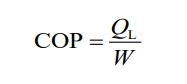
the refrigerator for a given amount of work, the better (more efficient) the
refrigerator is. Energy is conserved, so from the first law of thermodynamicswe can write
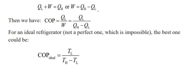
Example
An ideal refrigerator-freezer operates with a COP = 7.0 in a 24 oCroom. What is the temperature inside the freezer?
Solution
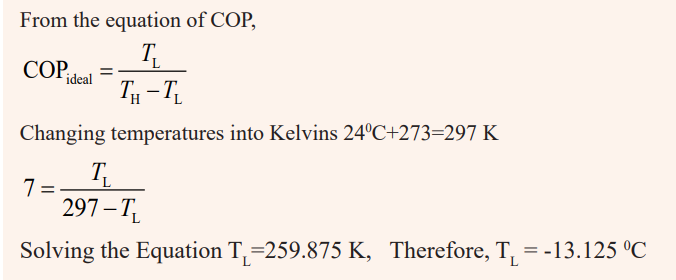
END UNIT ASSESSMENT
1. What is the heat capacity at constant volume considered to be more
important than at constant pressure?
2. Define: isothermal; isobaric; isovolumic and adiabatic processes
3. What is the relationship between the specific heat (or het capacities)
at constant pressure and at constant volume?
4. One mole of helium gas, initially at STP ( p1 latm kpa = 1.03
T1 =00c = 273.15 k) undergoes an isovolumetric process inwhich its pressure falls to half its initial value.
a) What is the work done by the gas?
b) What is the final temperature of the gas?
c) The helium gas then expands isobaric ally to twice its volume,what is the work done by the gas?
5. Find out the internal energy of a system which has constant volumeand the heat around the system is increased by 50 J?
6. In a certain process 8.0kcal of heat is furnished to the system while
the system does 6.00 KJ of work. By how much does the internalenergy of the system change during the process?
7. The specific heat of water is 4184J/kg.k. By how many joules does
the internal energy of 50g of water changes as it is heated from 210 c
to 370 c.