Unit 1 :Thin lenses

Key unit Competence
Explain the properties of lenses and image formation by lenses.
My goals
By the end of this unit, I will be able to:
* explain physical features of thin lenses
* state the types of lenses and explain their properties
* differentiate between lenses and curved mirrors
* explain the phenomenon of refraction of light by lenses
* construct the ray diagrams for formation of images by lenses
* explain the defects of lenses and how they can be corrected* describe the daily applications of lenses
INTRODUCTORY ACTIVITY
Using a hand lens, candle (object) and a plain paper (screen).
• Light the candle
• Place the candle hand lens and plain paper on the same line respectively
• Variate the position of the hand lens and sees the variation of the imageon the screen.
Questions
1. Discuss on the image formed on the screen (nature).
2. Try to draw a ray diagram of your observation and then discuss the
properties of the hand lens.
3. Discuss on the changes of your observation on the screen that are taking
place as you variate the positions of the hand lens.4. Discuss other types of lenses and brainstorm their different uses.
Introduction
The scientific study of light and optical material is involved in the making of
spectacles, cameras, projectors and optical instrument.
The most important optical materials are the various kinds of glass, but
many others such as plastics, polaroid, synthetics and natural crystals have
increasingly useful application.
In this unit we shall consider the behavior of certain component of lenses andits images formation.
Observe and think
Look at yourself in a flat mirror and choose one of the following that identifies
your observation;
a) my image is clearly seen without changes.b) my image shows some changes.
What do you think
a) What do you think about formation of your image by the mirror?b) What are the characteristics of this image formed?
Key conceptImage formation through a mirror.
Discovery activity
a) Look through a plain glass window and observe what happens. Discuss
with your neighbor on what is observed.
b) Look through an open window and discuss with your neighbor about the
observations.
c) Compare the observations in part (a) and (b) above.d) Look through the lenses and describe the nature of image formed.
What I discover
Just curved mirrors change images, certain transparent medium called lensalter what you see through them.
A lens is a transparent medium (usually glass) bound by one or two curved
surfaces. Different lenses give various natures of images depending on theircharacteristics.
Types of lenses and their characteristics
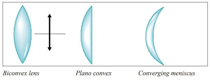
A lens is a piece of glass with one or two curved surfaces. The lens which is
thicker at the centre than at the edges is called a convex lens while the one
which is thinner at its centre is known as a concave lens. The curved surface of
the lens is called a meniscus. The lens in the human eye is thicker in the centre,and therefore it is a convex lens
Activity 1
Required Materials
• Notebook
• 2 convex lenses
• 2 concave lenses
• Flashlight or a torch bulb
• White paper
Procedure
1. Look closely at the lenses and answer these questions in your notebook:
a. How are the lenses shaped?
b. How are the lenses alike?
c. How are the lenses different?
2. Look through the lenses at the pages of a book, your hands, a hair,
and other things. Draw what you see in your notebook and label each
picture with the type of lens with which you observed the object. Be
sure to answer the following questions:
a. How does a concave lens make things look like?
b. How does a convex lens make things look like?
3. Lenses bend light in different directions. Shine a flashlight through
the lenses onto a piece of white paper and then answer the following
questions in your notebook:
a. In what direction do convex lenses bend light?
b. In what direction do concave lenses bend light?
4. Shine the flashlight through different combinations of lenses: two
convex lenses, two concave lenses, one concave and one convex lens.
Draw pictures of what you see and answer these questions:
a. What happens when you use multiple lenses at the same time?
b. Can you use two different lenses to make things far away appear
closer?
5. If you can, darken the room and place a convex lens between a sunlit
window and a white piece of paper. Place the lens close to the paper
and then slowly move the lens towards the window. Draw a picture of
what you see in your science notebook.
Do you see that rays change the direction after the lens? How do the emergentrays from each of the lenses behave?
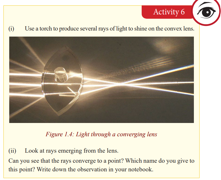
The light rays from the ray box change the direction after passing through the
lens. They are therefore refracted by the lens. Hence, lenses form images ofobjects by refracting light.
You can see that the rays from the convex lens are getting closer and closer
to a point. The rays are thus converging, and hence a convex lens is called a
converging lens. You can also see that the refracted rays from the concave lensare spreading out. This kind of lens is called diverging lens.
Summary:
1. A lens is a transparent medium (usually glass) bounded by one or two
curved surfaces. There are two types of lenses; a convex lens also called aconverging lens and a concave lens also known as a diverging lens.
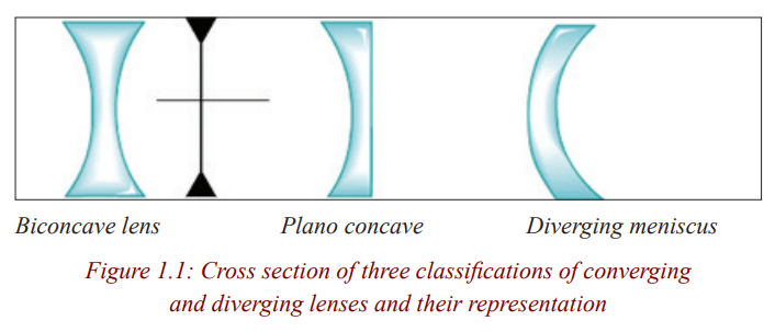
2. A convex lens is the one which is thicker at the centre than at the edges. A
concave lens is the one which is thinner at the centre than at the edges.
The figure below shows three classifications of convex lenses and threeclassifications of concave lenses.
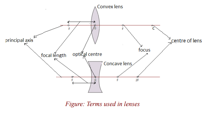
Terms used in lenses
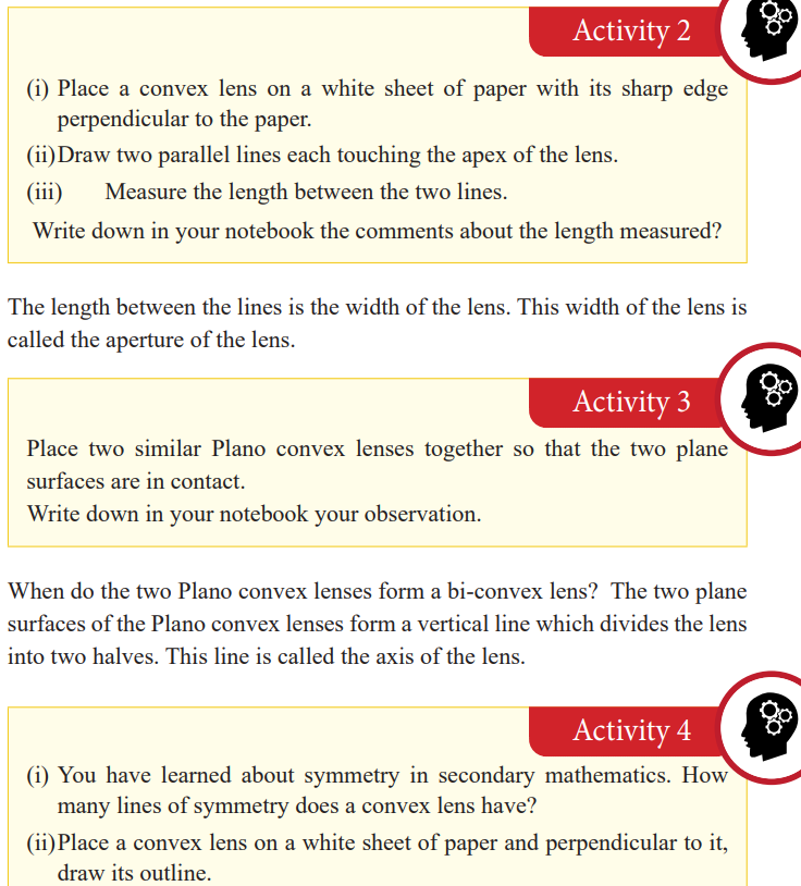
Lenses have two lines of symmetry, a vertical line and a horizontal line. The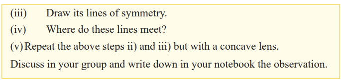
vertical line is called the axis of the lens (already seen in activity 2). Thehorizontal line is known as the principal axis of the lens.
Notice that these lines meet at a point. This point is the centre of the lens,called the optical centre of the lens denoted by O.
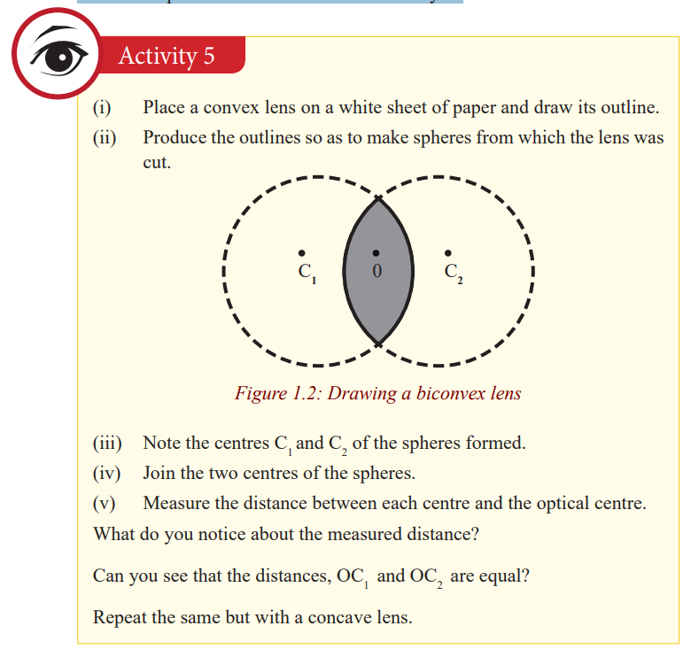
The centre of each sphere is called the centre of curvature of the surface of a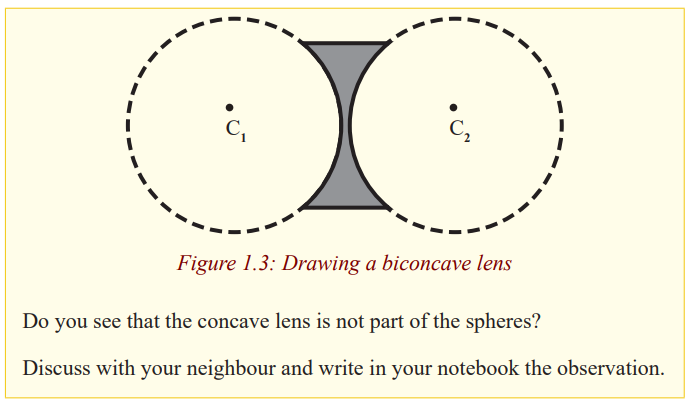
lens and the distance from the centre of curvature to the optical centre is the
radius of curvature of the surface. Since the convex lens forms part of thespheres, its centre of curvature is real and hence its radius of curvature.
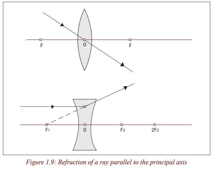
This point to which all parallel rays converge after refraction by a convex lens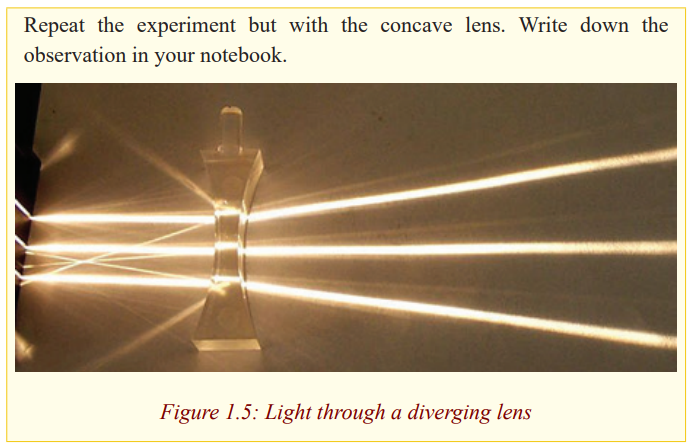
is called the principal focus of the convex lens.
The rays emerge from the lens when they are spreading out. They are diverged
and appear to come from a point. This point from which the rays appear todiverge after refraction by the concave lens is the principal focus of the lens.
Since rays converge to this point for the case of a convex lens, the principal
focus of a convex lens is real. The principal focus of a concave lens is virtualas the rays appear to come from it.
Repeat the above experiments by changing the lenses so that their right sidesbecome the left.
Do you see that the same thing happens for each?
Light can travel into the lens from the left or from the right. It therefore hastwo principal foci on both sides of the lens.
The principal focus of a lens is also called the focal point of the lens, and it isdenoted by F.
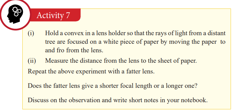
Since the image forms where the refracted rays meet and because the rays from
the distant tree are parallel, the piece of paper must then be at the principal
focus of the lens. This distance from the lens to the image is the focal length
of the lens. The focal length of the lens is thus the distance from the centre ofthe lens to the principal focus. It is always denoted by f.
The fatter lens has a shorter focal length, implying that the thicker the lens, theshorter the focal length and vice versa.
We have already seen that the lens has two principal foci. It means that theseprincipal foci are at equal distances on the opposite sides of the lens.
Repeat the experiment with the concave lens.
What do you notice?
The image cannot be seen. This is because the concave lens has a virtualprincipal focus.
Refraction of light through lenses
Lenses can be thought of as a series of tiny refracting prisms, each of which
refracts light to produce an image. These prisms are near each other (truncated)and when they act together, they produce a bright image focused at a point.
Each section of a lens acts as a tiny glass prism. The refracting angles of these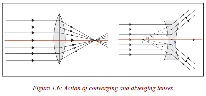
prisms decrease from the edges to its centre. As a result, light is deviated moreat the edges than at the centre of the lens.
The refracting angles of the truncated prisms in a converging lens point to theedges and so bring the parallel rays to a focus.
The truncated prisms of the diverging lens point the opposite way to those of
the converging lens, and so a divergent beam is obtained when parallel rays
are refracted by this lens because the deviation of the light is in the oppositedirection.
The middle part of the lens acts like a rectangular piece of glass and a rayincident to it strikes it normally, and thus passes undeviated.
Properties of images formed by lenses
Rays come from all points on the objects. Where these rays meet or appear to
meet after refraction by the lens is the position of the image.
Notice that an image cannot be seen on the screen irrespective of the position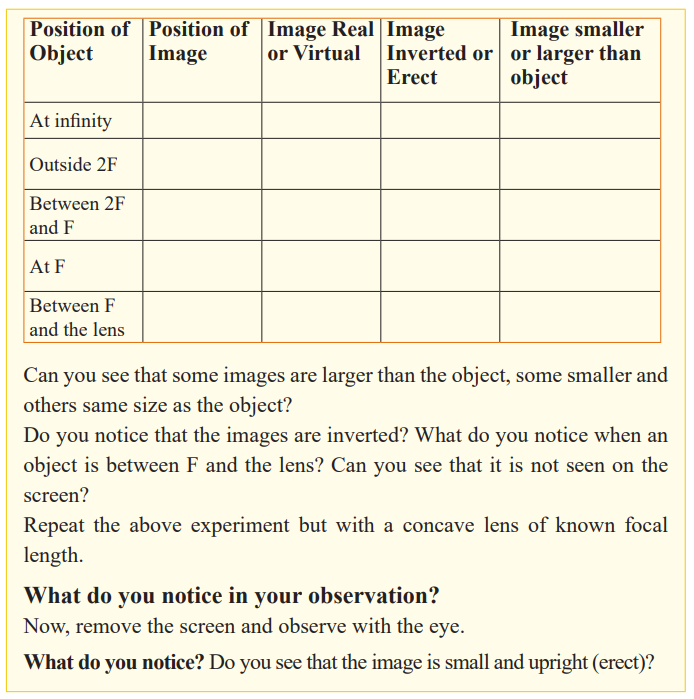
of the object. The nature of the image formed by a convex lens depends on theposition of the object along the principal axis of the lens.
The principal focus of a lens plays an important part in the formation of an
image by a lens since parallel rays from the object converge to it, and thus,
we consider points F and 2F when describing the nature of the images formed
by the lens. These images can be larger or smaller than the object or same
size as the object. When an image is larger than the object, we say that it is
magnified and when it is smaller, we say that it is diminished. Images which
can be formed on the screen are Real images. Because light rays pass through
these images, real images can be formed on the screen. All real images formedby the convex lens are inverted.
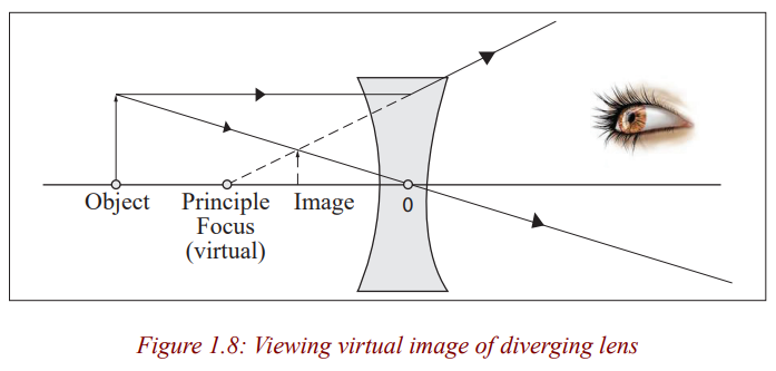
When an object is between F and the lens, there is no image formed on the
screen. The image formed is not real and is only seen by removing the screen
and placing an eye in its position. We say that it is a virtual image. For a
virtual image, rays appear to come from its position. Unlike for a convex lens
where the nature of the image depends on the position of the object, a concave
lens gives only an upright, small, virtual image, and is situated between theprincipal focus and the lens for all positions of the object.
Critical thinking:
1. Design an experiment to study images formed by convex lenses of
various focal lengths. How does the focal length affect the position and
size of the image produced?
2. Suppose you wanted to closely examine the leaf of a plant, which typeof a lens would you use? Explain your decision.
Ray diagrams and properties of images formed by lenses
We have already seen that an image is formed where rays from the object
meet. Rays come from all points on the objects. However, for simplicity, only
a few rays from one point are considered when drawing ray diagrams. Where
these rays meet or appear to meet after refraction by the lens is the position ofthe image.
To locate the position of the image, two of the following three rays are
considered.
1. A ray parallel to the principal axis which after refraction passes throughthe principle focus or appears to come from it.
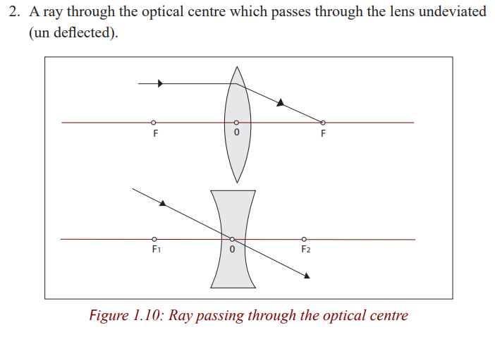
The central part of a lens acts as a small parallel –sided block which slightly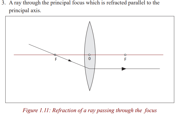
displaces but does not deviate a ray passing through it and for a thin lens, thedisplacement can be ignored.
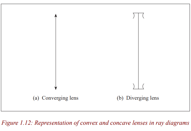
In ray diagrams, a thin lens is represented by a straight line at which all the
refraction is considered to occur. In reality, bending takes place at each surfaceof the lens.
Ray diagrams for a convex lens
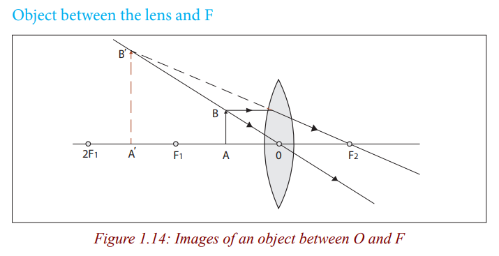
Nature of imageThe image is virtual, erect, larger than the object and behind the object.
Application activity 1.1How is this lens useful when the object is in this position?
Nature of image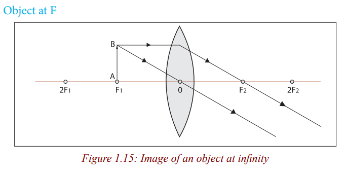
The image is formed at infinity.
Application activity 1.2
Can you think of how useful is the lens when an object is at its focal point?What is it?
Nature of image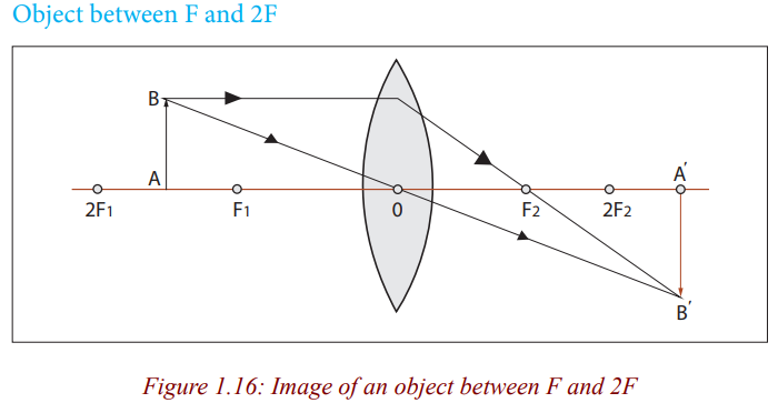
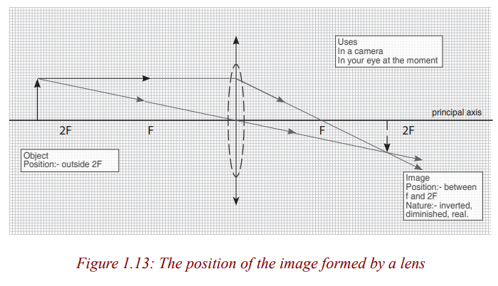
The image is real, inverted, larger than object (magnified) and beyond 2F.
Application activity 1.3How is the lens useful when the object is in the above position?
Nature of image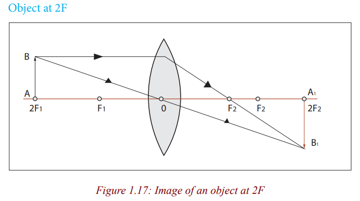
The image is real, inverted and same size as object.
The image is real, inverted, smaller than object (dimensional) and is formed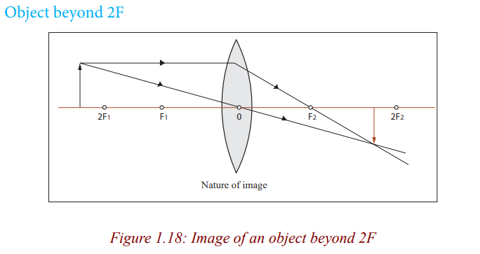
between F and 2F.
Application activity 1.4
What can be a daily application of the lens when an object is in thisposition?
Nature of image
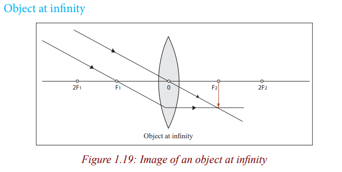
The image is real, inverted, smaller than object and is formed at F.
When an object is between the lens and the principal focus, the rays from the
object never converge, instead they appear to come from a position behind
the lens. In this case, the lens is used as a simple magnifying glass because itforms an upright and magnified image (Figure 1.14).
When an object is at the principal focus of the lens, refracted rays emerge from
the lens parallel to each other, and the lens is used as a search light torch, andtheatre spotlights (Figure 1.15).
Figure 1.16 shows that when an object is between F and 2F, the lens forms amagnified real image. In this case, a lens is used as a film projector.
When an object is beyond 2F (Figure 1.18), a lens forms real and small image.
The lens is used as a camera because this small, real image can be formed ona piece of film.
Ray diagrams for a concave lens
Accurate construction of ray diagrams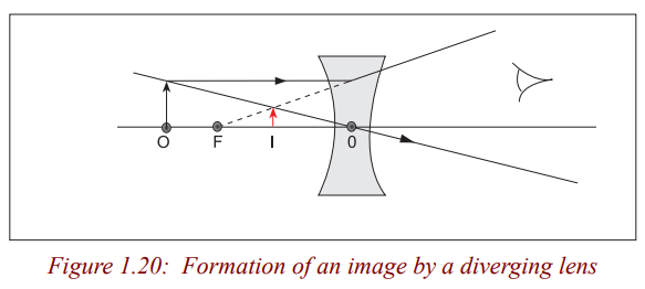
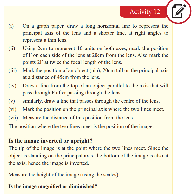
Problems for locating the position of the image can be solved by constructinga ray diagram as an accurate scale drawing on a graph paper.
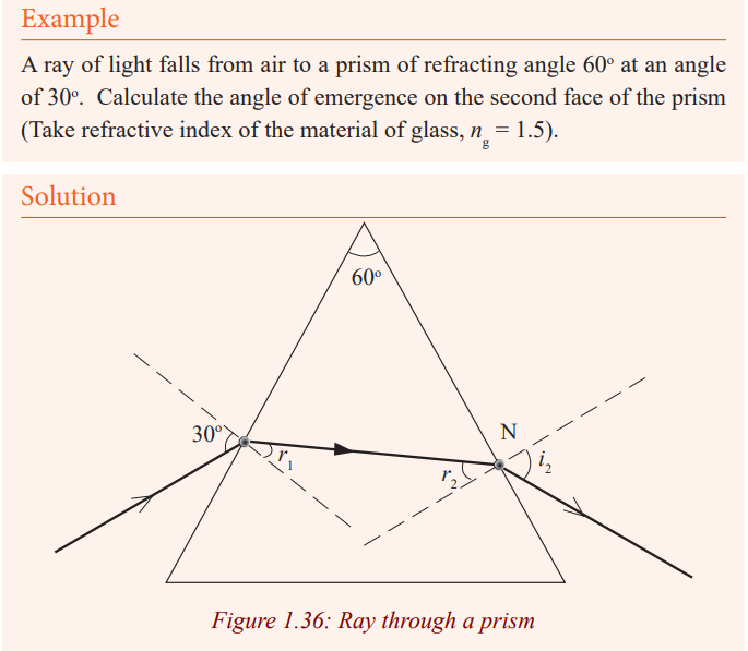
Example
1. An object is placed 40 cm away from a diverging lens of focal length
20cm. If it is 2 cm high, determine graphically the position, size and
nature of the image.
2. Let 1cm on the paper represent 10 cm on the horizontal axis and 1cmon the vertical axis of the actual distance.
The image is virtual, erect, 0.7cm tall and is formed at 13cm from the lens on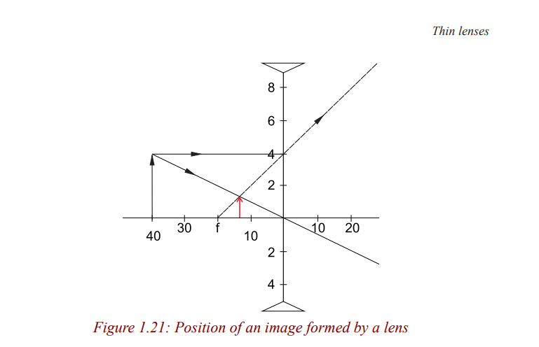
the same side as the object.
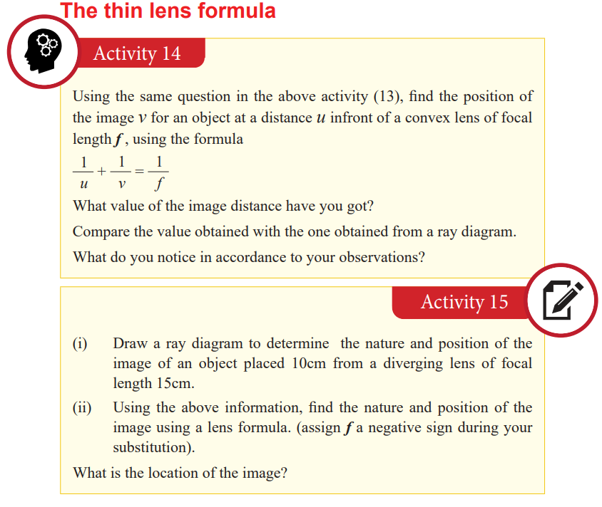
The thin lens formula
The sign convention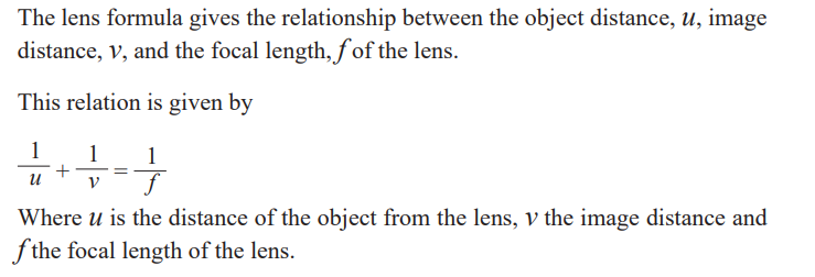
From activity 13, we notice that all the distances are measured from the
optical centre and in activity 14, we substituted for u, v and f using positive
numerical values. It therefore follows that distances of real images and realprincipal focus are positive.
In activity 14, then you will notice that the image distance from the lens is
negative but equal to the distance determined graphically. This distance is
obtained by using a negative numerical value of the focal length. Since a
concave lens has a virtual principal focus, and forms virtual images, distances
of virtual images and virtual principal foci are negative. Sign convention
states that real is positive while virtual is negative. This should be put underconsideration when one is using the lens formula to solve problems.
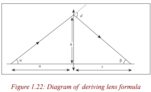
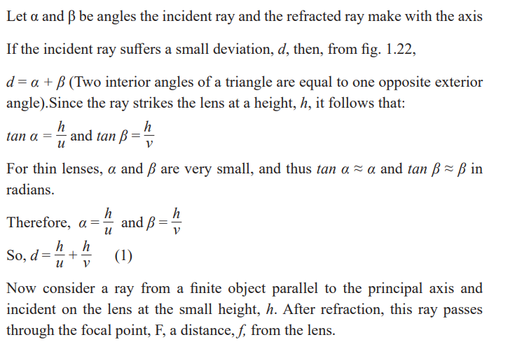
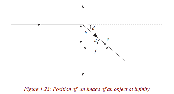
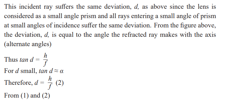
Derivation of the lens formula
Convex lens
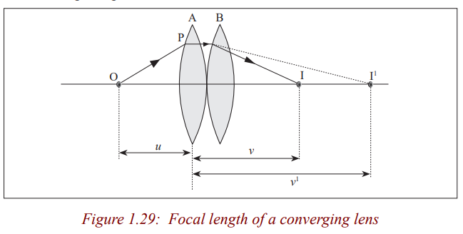
Consider a point object O on the principal axis, at a distance, u greater than thefocal length from the lens.
Suppose that a ray from O is incident on the lens at a small height h above theaxis and is refracted to form an image I at a distance v from the lens.
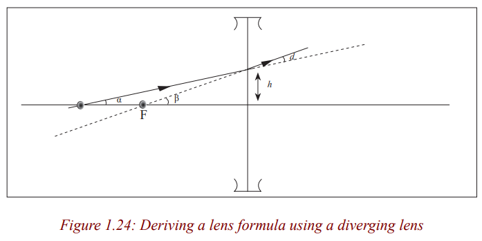
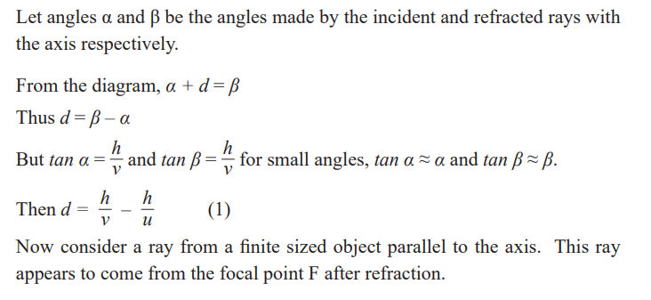
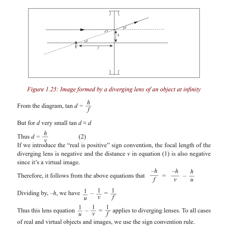
Concave lens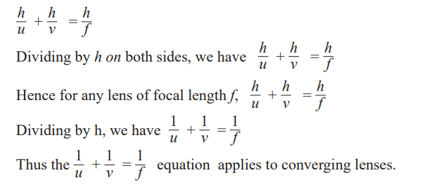
Consider a point object O on the principal axis of the diverging lens at adistance, u, so that its image is formed at a distance, v.
Application activity 1.5
1. An object is placed 12cm from a converging lens of focal length 18
cm. Find the nature and the position of the image.
2. Find the nature and position of the image of an object placed 15cmfrom a diverging lens of focal length 15cm.
Critical thinking exercise
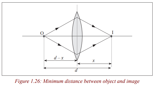
Least possible distance between object and real image with converging lens
Experiments show that it is not always possible to obtain a real image on a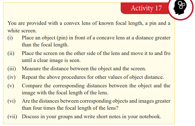
screen although the object and the screen may both be at a greater distance
from a converging lens than its focal length. Theory shows that the minimum
distance between the object and the screen for an image to be formed is four
times the focal length, f. Therefore, the distance between an object and ascreen must be equal to or greater than four times the focal length.
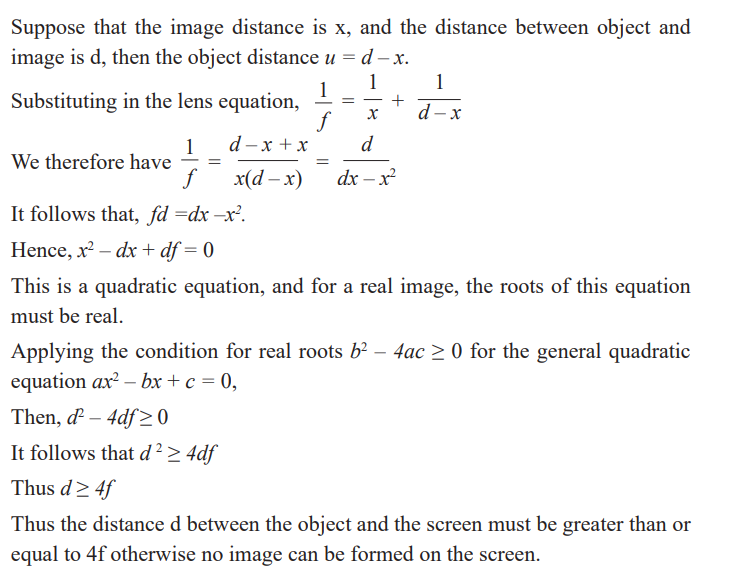
Consider a point object O on the principal axis of a converging lens forming an image I.
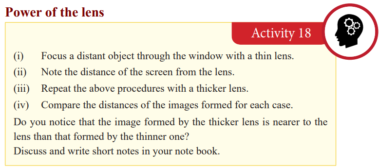
Since the image formed by the thicker lens is nearer, the thicker lens is more
powerful than the thinner lens of the same material. We have already seen that
an image of a distant object forms at the focus of the lens and the thicker the
lens the shorter the focal length. So the power of the lens depends on its focal
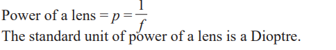
length, that is, as the focal length becomes shorter, the power increases. Thepower of the lens is defined as the reciprocal of its focal length in metres.
Application activity 1.6
1. Calculate the power of the lens of focal length of 15 cm.2. A converging lens has a power of 0.02D, what is its focal length?
Determination of the focal length of the lens
Converging lens
Rough method
The distance from the lens to the screen is the focal length of the lens since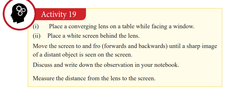
rays from a distant object strike the lens when they are parallel.
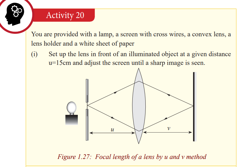
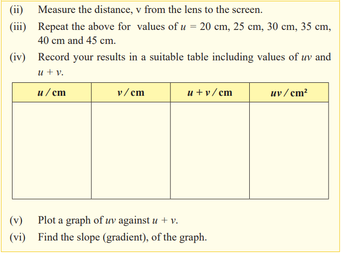
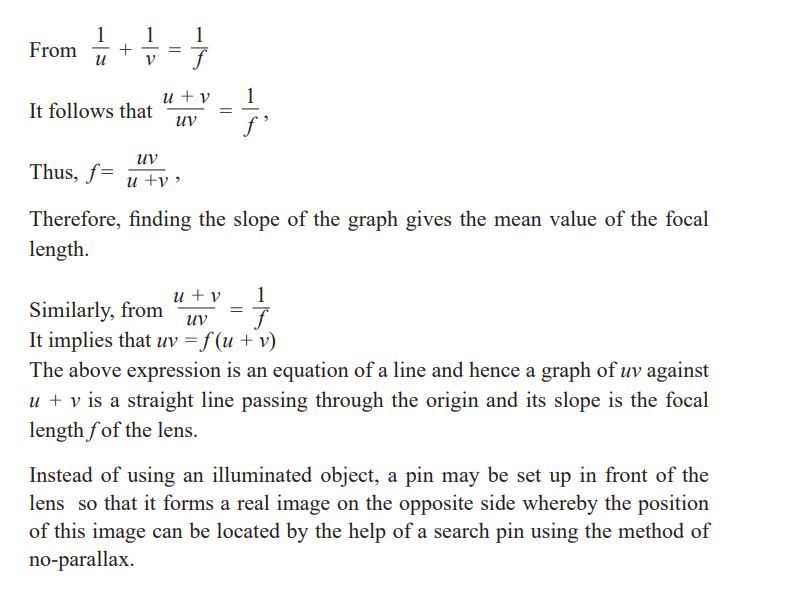
Graphical determination of focal length of a convex lens
Diverging lens
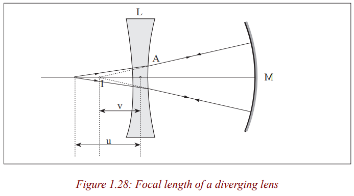
Determination of focal length of a diverging lens by Concavemirror method
We have already seen that a concave lens forms virtual images of real images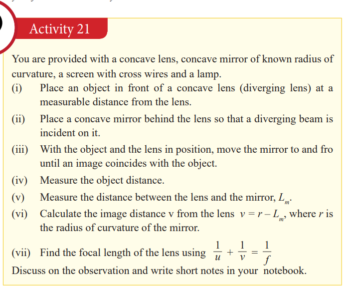
which cannot be seen on the screen. So, to determine the focal length of a
diverging lens, we need to form a virtual object for the diverging lens so that
a real image is produced. This is achieved in the experiment by putting a
concave mirror behind the lens so as to reflect back the diverging rays fromthe lens.
As you saw in your lower secondary classes, when an object is placed at the
principal focus of a concave mirror, the image is formed at the same position
with it. Now, since the object and its image are coinciding, it means that they
are at the centre of curvature of the mirror; v is negative as I is a virtual image
for the lens, and as the object and image are coincident, the rays must be
incident normally on the mirror M. Thus, reflected rays from the mirror passthrough its centre of curvature which is the position of the virtual image.
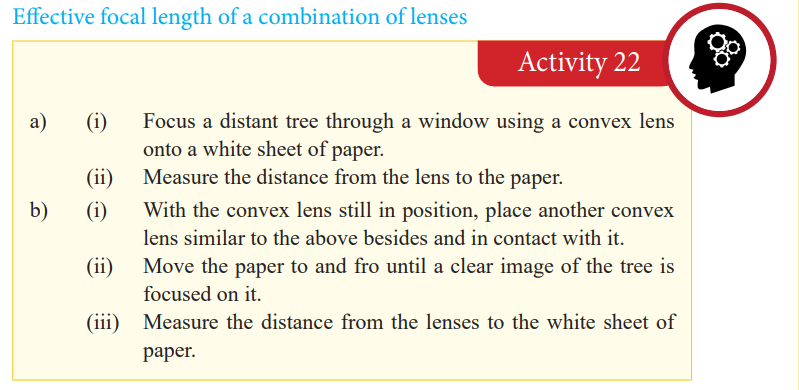
Combination of lenses
In our next unit, we shall talk about instruments which use lenses to focus
objects. Among others, a microscope uses a combination of two lenses tofocus objects.
Application activity 1.7
1. An object O is placed 12cm from a thin converging lens P of focal
length 10cm and an image is formed on a screen S on the other side of
the lens. A thin diverging lens, Q is now placed between the converting
lens and S, 50cm from the converging lens. Find the position and
nature of the final image if the focal length of the diverging lens is15cm.
2. An object is placed 6.0cm from a thin converging lens A of focal
length 5.0cm. Another thin converging lens B of focal length 15cm is
placed co-axially with A and 20cm from it on the side way from theobject. Find the position, nature and magnification of the final image.
Defects of lenses and their corrections
Notice that the image has coloured patches. This defect where by an image
formed has coloured patches is called chromatic aberration.
There are two kinds of defects; spherical aberration and chromatic aberration.
Spherical aberration
This arises in lenses of larger aperture when a wide beam of light incident on
the lens, not all rays are brought to one focus. As a result, the image of the
object becomes distorted. The defect is due to the fact that the focal length
of the lens for rays far from the principal axis are less than for rays closer to a
property of a spherical surface and as a result, they converge to a point closerto the lens.
This defect can be minimised (reduced) by surrounding the lens with an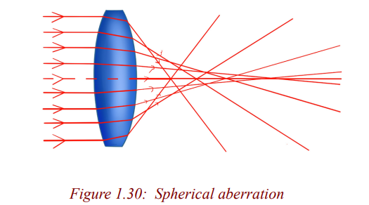
aperture disc having a hole in the middle so that rays fall on the lens at a point
closer to its principal axis. However, this reduces the brightness of the imagesince it reduces the amount of light energy passing through the lens.
Chromatic aberration
This occurs when white light from an object falls on a lens and splits it into its
component colours. These colours separate and converge to different foci, andthis results into an image with coloured edges.
The separation takes place because the material of a glass of a lens has different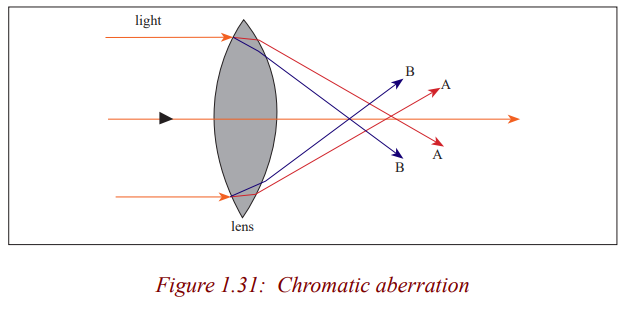
refractive indices for each colour. The colours travel at different speeds in
glass: red colour with the greatest and the violet with the least. As a result,violet is deviated most and red is the least deviated
Thus, a converging lens produces a series of coloured images of an extendedwhite object as shown in the figure above (exaggerated for clarity).
Chromatic aberration can be minimised by using an achromatic lens called an
achromatic doublet. This consists of a converging lens of crown glass combinedwith a diverging lens of flint glass cemented together with Canada balsam.
The flint glass of the diverging lens produces the same dispersion as the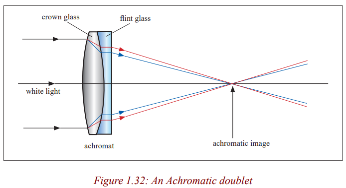
crown glass of the converging lens but in the opposite direction and the
overall combination is converging. As a result, the achromatic combinationconverges the white light to one focus.
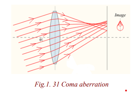
Coma aberration
Another type of aberration is coma, which derives its name from the comet-like
appearance of the aberrated image. In general, a bundle of parallel rays
passing through the lens at a fixed distance from the centre of the lens arefocused to a ring-shaped image in the focal plane, known as a comatic circle.
The sum of all these circles results in a V-shaped or comet-like flare. As with
spherical aberration, coma can be minimized by choosing the curvature of the
two lens surfaces to match the application. Lenses in which both sphericalaberration and coma are minimized are called best form lenses.

Refraction through prisms
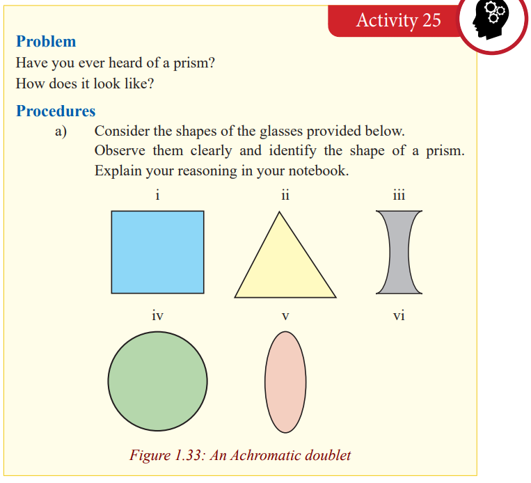
In optics, a prism is transparent material like glass or plastic that refracts light.
Atleast two of the flat surfaces must have an angle less than 90o between them.The exact angle between the surfaces depends on the application.
Terms associated with refraction through prism
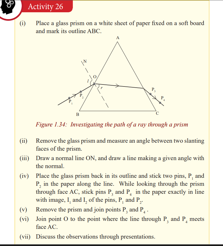
The position and shape of the third side of the prism does not affect the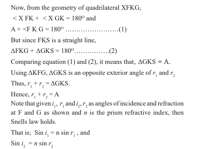
refraction under consideration and so is shown as an irregular in Fig.
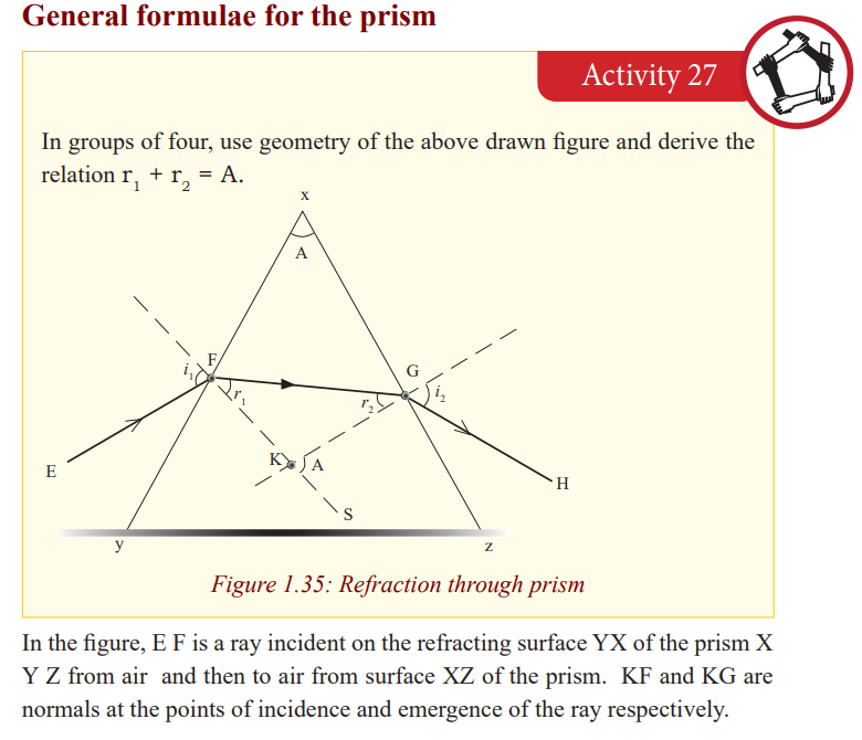
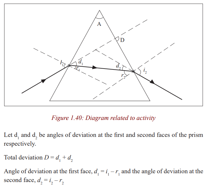
Deviation of light by a prism
Light can be deviated by reflection and refraction. Since a prism refracts light,
it therefore changes its direction.
A prism deviates light on both faces. These deviations do not cancel out as in a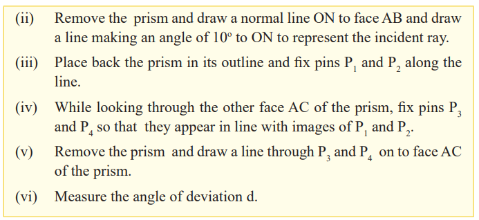
parallel sided block where the emergent ray, although displaced, is parallel to
the incident ray surface. The total deviation of a ray due to refraction at both
faces of the prism is the sum of the deviation of the ray due to refraction at thefirst surface and its deviation at the second face.
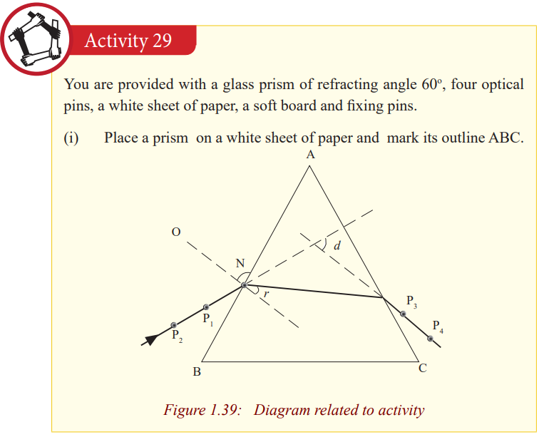
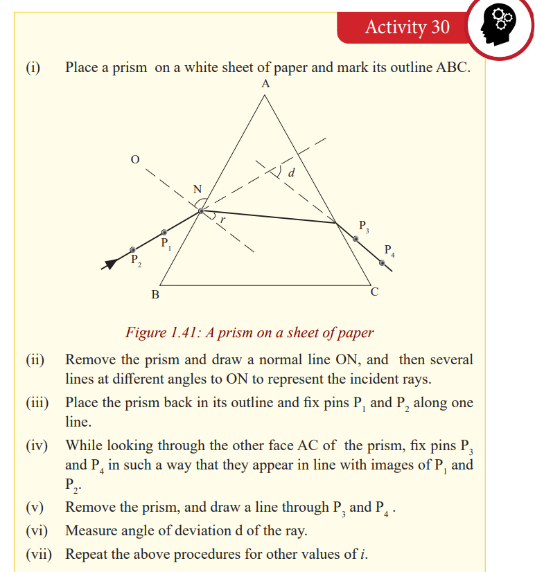
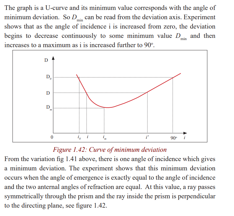
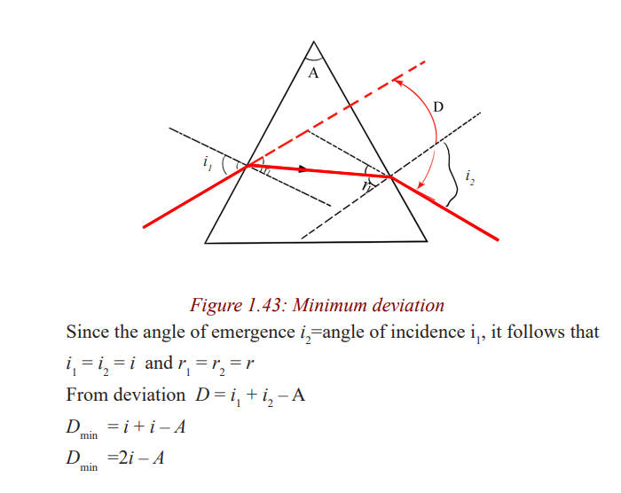
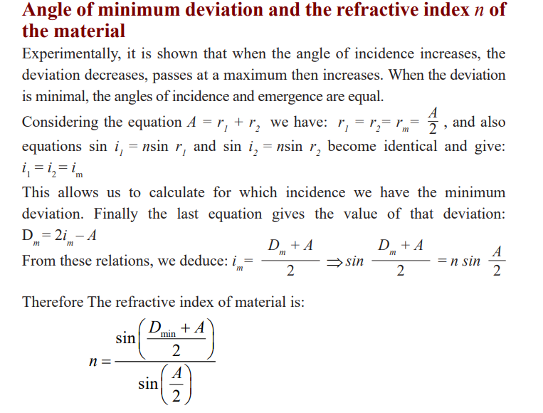
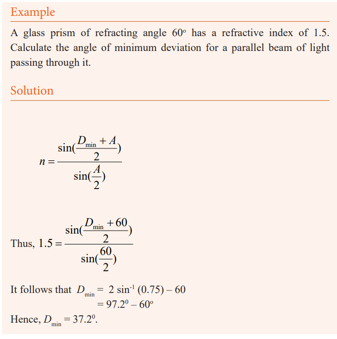
Angle of minimum deviation and determination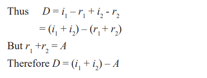
of refractive index n of a material of the prism
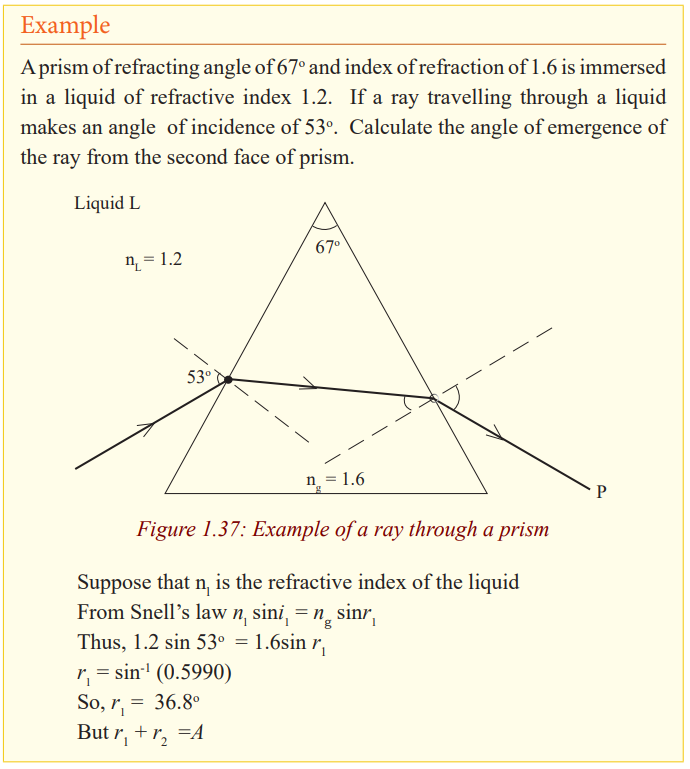
Application Activity 1.8
A glass prism of refracting angle 72o
and index of refraction 1.66 is immersed
in a liquid of refractive index 1.33. What is the angle of minimum deviationfor a parallel beam of light passing through the prism?
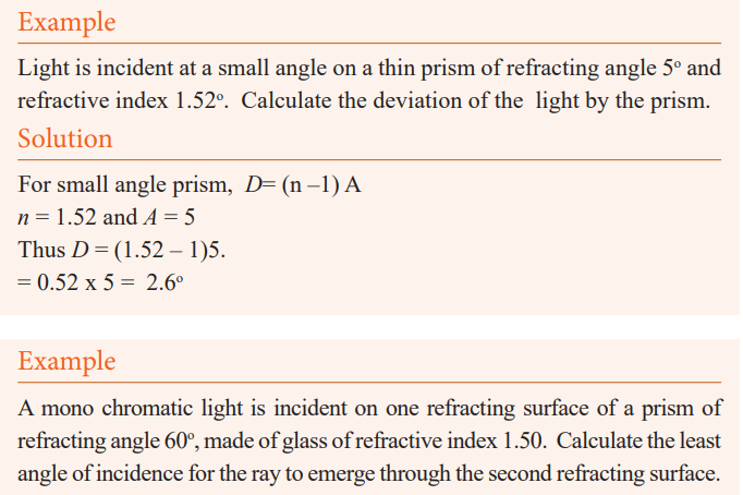
Deviation of light by a small angle prism
Consider a ray incident almost normally in air in a prism of small refracting
angle A (less than about 60 or 0.1 radian) so that the angle of incidence i issmall.
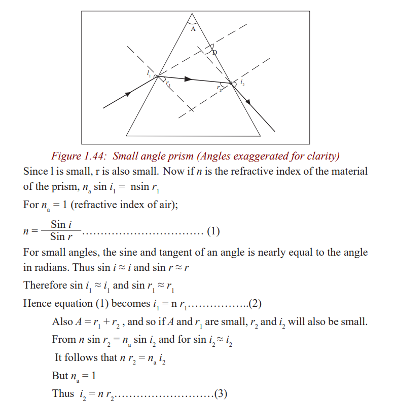
The expression D = A (n – 1) shows that for a given angle A, all rays entering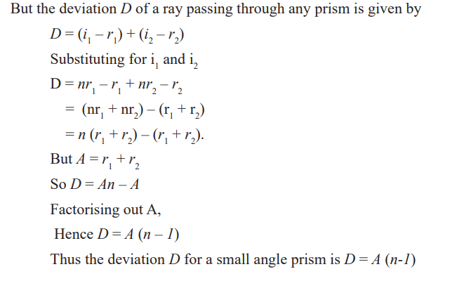
a small angle prism at small angles of incidence suffer the same deviation.
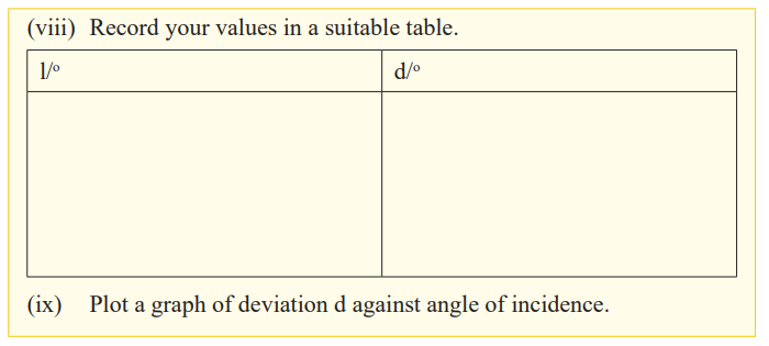
Determination of refractive index of a material of a prism
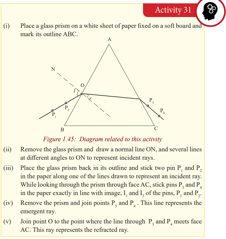
The graph is a straight line graph and the gradient represents the mean value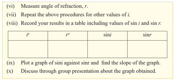
which is the refractive index of the material.
Dispersion of light by a prism
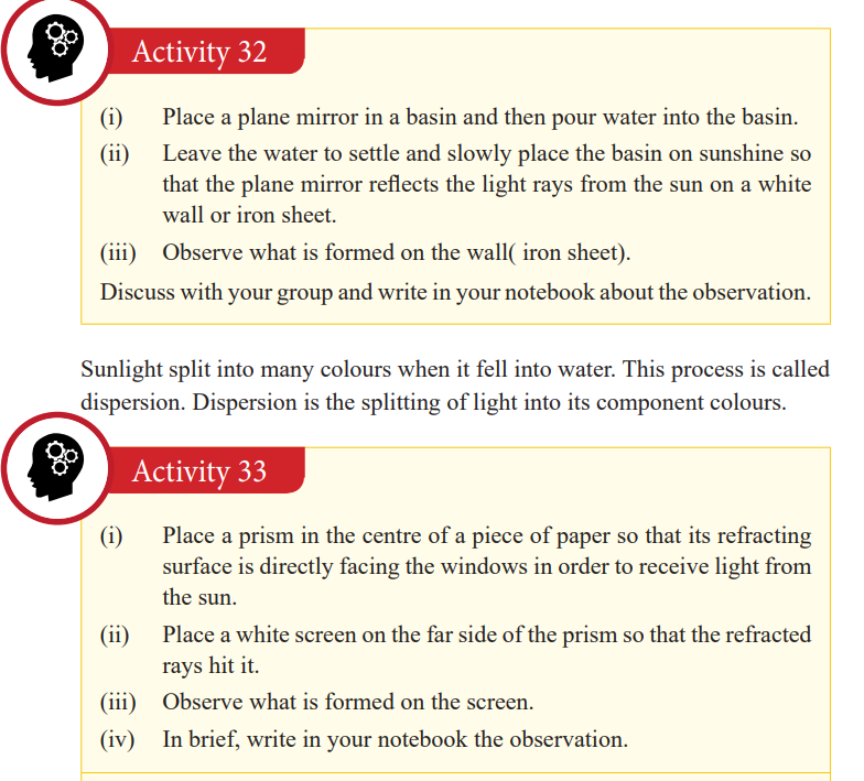
A band of seven colours is formed on the screen. The colours are in order of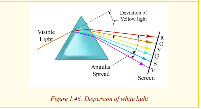
Red, orange, yellow, green, blue, indigo and violet (ROYGBIV) which are
colours of rainbow. This band of colours is called a spectrum. Thus, when
a narrow beam of white light falls on a glass prism, it splits into a range
of colours and these colours separate to form a spectrum, a process called
dispersion. This occurs because white is not a single colour but mixture of all
colours of the rainbow. The prism refracts each colour by a different amount
because the colours travel at different speeds in the glass and thus the glass
has different refractive indices for each colour. The speed of a red colour is
greatest and that of a violet colour is the least, and so the refractive index of a
material of the prism for red colour is the least and that of the violet colour is
the greatest. Now it follows that since the angle of incidence in air is the same
for all the colours, red in deviated least by the prism and the violet rays are the
most deviated as shown in the figure above (exaggerated for clarity because
the colours overlap).
Applications of total internal reflection of light by a prism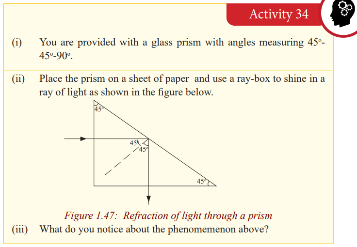
Notice that light goes straight through the first surface and when it meets the
second surface, it is internally reflected. So, the long side of the prism acts as
a mirror and turns light through an angle of 90o
. Two prisms of the same type
as above can be arranged in away and used in a periscope; an instrument used
to see the top of an obstruction.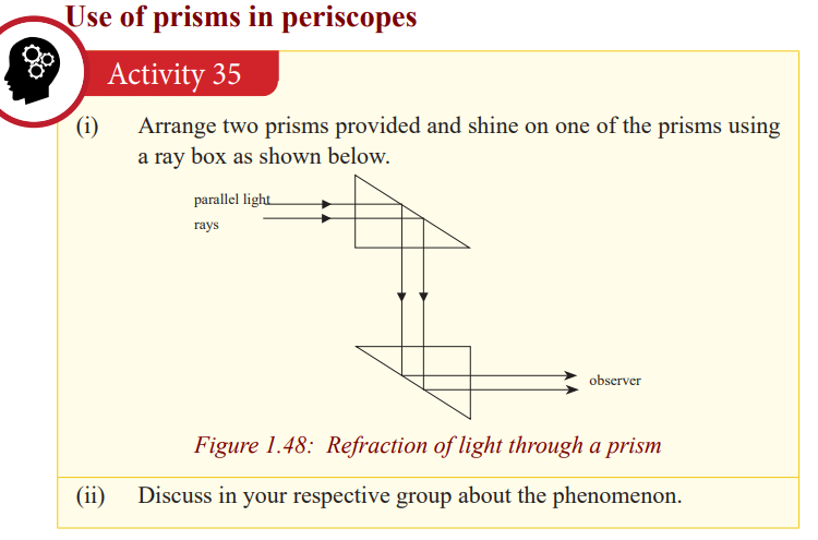
Light is tuned through 90oat each prism and it emerges parallel to the incident
light. In prism periscopes, light from an object is turned through 90o
at each prism ands reaches the observer at a different altitude to that of an object. Sothe image of the object is formed at another altitude but is same size as object.
An arrangement of two prisms each turning light through an angle of 180o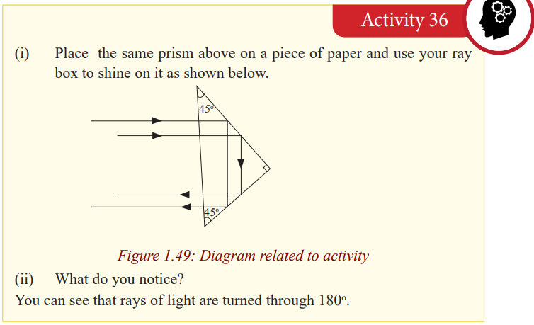
is used in prism binoculars; instruments used to view hidden objects. This willbe discussed in the next unit.
Critical Thinking Exercise
a) Give reasons why prism rather than plane mirrors are used in
periscopes and prism binoculars.b) Explain why diamonds are cut with their sides flat and others slanting.
In periscopes and prism binoculars, plane mirrors can be used but prisms arepreferred because of the following reasons.
In the first place, a prism allows light to undergo total internal reflection and
thus the images are formed by total internal reflection where as a mirror allows
light to both reflect and refract at its surface. So for a prism, all the light
(100%) from the object is reflected but for a mirror some light is absorbed
(about 95% is reflected) and thus a prism produces a brighter image than amirror
The silvering on the mirrors wears off with time but with prism no silveringis needed.
Some mirrors, for example, thick plate mirrors produce multiple images of
one object because of reflections and refractions at the surfaces and inside theglass but a prism produces anyone image.
Diamonds are cut that way so as to make use of total internal reflection. Themultiple reflections inside diamond make it bright.
END UNIT ASSESSMENT
1. An object of height h = 7 cm is placed a distance p = 25 cm in front of athin converging lens of focal length f = 35 cm.
a) What is the height, location, and nature of the image?
b) Suppose that the object is moved to a new location a distance p
= 90 cm in front of the lens. What now is the height, location,
and nature of the image?
2. How far must an object be placed in front of a diverging lens of focal
length 45 cm in order to ensure that the size of the image is fifteen
times less than the size of the object? How far in front of the lens is the
image located?
3. An object is placed (a) 20 cm, (b) 5 cm from a converging lens of focal
length 15 cm. Find the nature, position and magnification of the image
in each case.
4. Find the nature and position of the image of an object placed 10 cm from
a diverging lens of focal length 15 cm.
5. A coin 3 cm in diameter is placed 24 cm from a converging lens whose
focal length is 16 cm. Find the location, size, and nature of the image.
6. An object is placed 30.0 cm in front of a converging lens and then 12.5
cm in front of a diverging lens. Both lenses have a focal length of 10.0
cm. for both cases, find the image distance and describe the image.
7. A 4.00 cm tall light bulb is placed a distance of 45.7 cm from a double
convex lens having a focal length of 15.2 cm. Determine the image
distance and the image size.
8. A 4.00 cm tall light bulb is placed a distance of 8.30 cm from a double
convex lens having a focal length of 15.2 cm. Determine the image
distance and the image size.
9. A 4.00 cm tall light bulb is placed a distance of 35.5 cm from a diverging
lens having a focal length of 12.2 cm. Determine the image distance and
the image size.
10.A beam of parallel rays spreads out after passing through a thin diverging
lens, as if the rays all came from a point 20.0 cm from the center of the
lens. You want to use this lens to form an erect, virtual image that is the
height of the object.
a) Where should the object be placed? Where will the image be?
b) Draw a principal ray diagram.
11.A ray of light incident at an angle i on a prism of angle, A, passes
through it symmetrically. Write an expression for the deviation, d, of
the ray in terms of i and A. Hence find the value of d, if the angle of the
prism is 60o and the refractive index of the glass is 1.48.
12.A beam of monochromatic light in incident normally on the refracting
surface of a 60o glass prism of refractive index 1.62. Calculate the
deviation caused by the prism.
13. a) Define the critical angle of a medium.
b) One side of a triangular glass prism put in a pool of water of
refractive index 4/3 and the other side was left open to air. A ray
of light from water was incident on the prism at an angle i = 21.7o. The
light just grazes as it emerges out of the prism. Given that the
refractive index of glass 1.52, determine the refracting angle A ofthe prism.
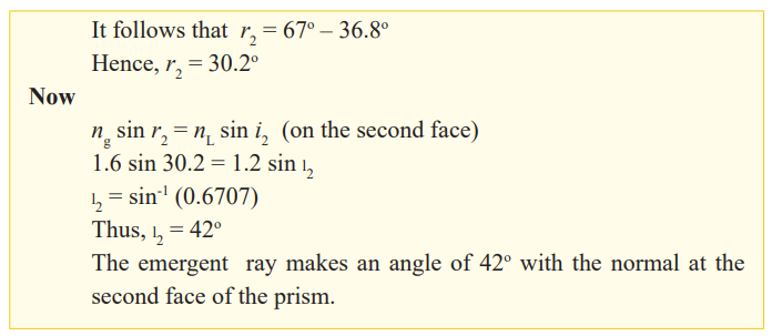
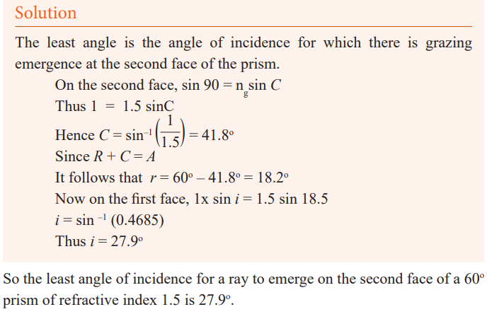
14.A monochromatic light is incident at an angle of 45o
on a glass prism of refracting angle 70o
in air. The emergent ray grazes the boundary of
the other refracting surface of the prism. Find the refractive index ofthe material of glass.
15.A prism of diamond has a refracting angle of 60o
. A ray of yellow light is incident at an angle of 60o
on one face. Find the angle of emergenceif the refractive index of diamond for yellow light is 2.42.
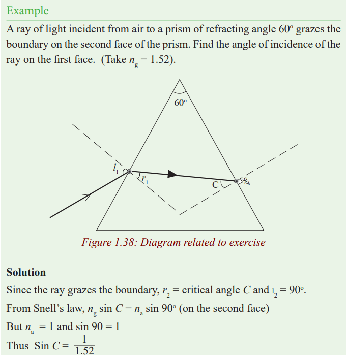
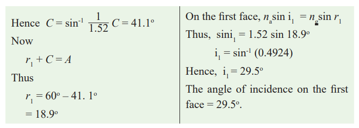
16.A ray of light just undergoes total internal reflection at the second face
of a prism of refracting angle 60o
and refractive index 1.5. What is itsangle of incidence on the first face?
17.A sharp image is located 78.0mm behind a 65.0mm-focal-length
converging lens. Find the object distance (a) using a ray diagram, (b)by calculation.
18.What is (a) the position, and (b) the size of the image of a 7.6cm high
flower placed 1.00m from a 50.0mm focal length camera lens?
19.An object is placed 10cm from a lens of 15m of focal length.Determine the image position.
20.Two converging lenses A and B, with focal lengths fA=20cm and fB =
-25cm, are placed 80cm apart, as shown in the figure (1). An object is
placed 60cm in front of the first lens as shown in figure (2). Determine
(a) the position, and (b) the magnification, of the final image formed bythe combination of the two lenses.
21.Where must a small insect be placed if a 25cm focal length diverging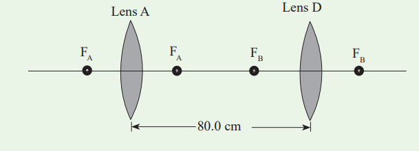
lens is to form a virtual image 20cm in front of the lens?
22.Where must a luminous object be placed so that a converging lens of
focal length 20cm produces an image of size four times bigger than theobject (Consider the case of a real image and the case of a virtual)
23.From a real object AB we want to obtain an inverted image four
times bigger than the object. We place a screen 5m away the object.
Specify the kind, the position and the focus of the lens to use. Give thegraphical and the algebraic.
24.In cinematography the film is located at 30m from the screen and the
image has a magnification of 100. Determine the focal length of thelens used in projection
25.An object AB of 1cm is placed at 8cm from a converging lens of focallength 12cm. Find its image (Position, nature and the size).
26.An object of 2cm is placed at 50cm from a diverging lens of focallength 10cm. Determine its image.
27.An object located 32.0 cm infront of a lens forms an image on a screen
8.00 cm behind the lens. (a) Find the focal length of the lens. (b)Determine the magnification. (c) Is the lens converging or diverging?
28.A movie star catches the reporter shooting pictures of her at home. She
claims the reporter was trespassing. To prove her point, she gives as
evidence the film she seized. Her 1.72m height is 8.25mm high on the
film and the focal length of the camera lens was 210mm. How far awayfrom the subject was the reporter standing?
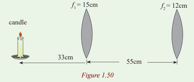
29.A lighted candle is placed 33cm in front of a converging lens of focal
length f1=15cm, which in turn is 55cm in front of another converging
lens of focal length f2=12cm. (a) Draw a ray diagram and estimate
the location and the relative size of the final image. (b) Calculate theposition and relative size of the final image.
30.When an object is placed 60cm from a certain converging lens, it forms
a real image. When the objet is moved to 40cm from the lens, the
image moves 10cm farther from the lens. Find the focal length of thislens.