UNIT 6 BLOCK DIAGRAM OF TELECOMMUNICATION
Key unit competence: Construct and analyze block diagram of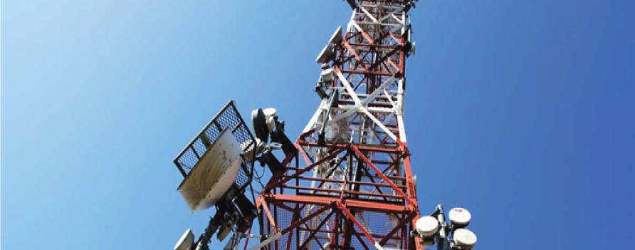
telecommunication systems.
My goals
• Identify parts of a block diagram of telecommunication system.
• Differentiate oscillator, modulator and amplifier.
• Outline the function of a microphone and antenna.
• Describe terms applied in telecommunication systems
• Construct, analyse and judge block diagrams of a telecommunication
system.
• Realise that parts of a telecommunication system are dependent
INTRODUCTORY ACTIVITY
Investigating the function of wireless microphone
Materials:
• Wireless microphone set
• Amplifier and mixer
• Connecting wires
• Speaker
Procedure:
Connect the full sound system such that the signal will be transmitted to the
speakers using wireless microphone.
Questions:
1. How is your voice getting to the speakers?
2. Where else this system is used?3. What are advantages and disadvantages of communication?
6.1. OPERATING PRINCIPLE OF MICROPHONE
ACTIVITY 6.1: Investigating the function of a microphone
Take the case of two people talking on telephone (see Fig.6.1). Observethe image below and answer to the following questions:

Fig.6. 1 People talking on telephone
1. Discuss the functioning process of a telephone.2. Differentiate the functions of a microphone from that of a speaker.
Telecommunication in real life is the transmission of signals and other types
of data of any nature by wire, radio, optical or other electromagnetic systems of
communication. Telecommunication occurs when the exchange of information
between communicating participants includes the use of signs or other
technologically based materials such as telephone, TV set, radio receiver, radio
emitter, computer, and so on. All can be done either mechanically, electrically
or electronically.
The use of microphones began with the telephone in the nineteenth century.
The requirements were basically those of speech intelligibility, and the carbon
microphone, developed early in that art, is still used in telephones today.
Particles of carbon are alternately compressed and relaxed by the diaphragm
under the influence of sound pressure, and the resulting alternation of
resistance modulates the current proportionally to the change in resistance.
Carbon microphones are noisy; they have limited dynamic range and produce
high levels of distortion. However, none of these defects is really serious in its
application to telephony.
Operating principle of microphones
A microphone converts sound vibrations into electrical entity. Basically a
microphone has a diaphragm which moves when sound pressure pushes it. This
movement can be converted into proportional voltage using several possibletransducers.
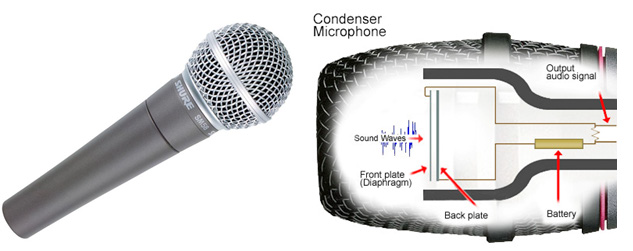
Fig.6. 2: The outer and internal view of a microphone
A transducer is a device which receives electrical, mechanical or acoustic
waves from one medium and converts them into related waves for a similar or
different medium. Thus, it can be said that a microphone is a transducer that
converts acoustical sound energy into electrical energy. Its basic function is
therefore to convert sound energy into electrical audio signals which can be
used for further processing. Microphones are classified based on constructionand directivity.
6.2 CHANNELS OF SIGNAL TRANSMISSION
ACTIVITY 6.2: Investigating signal transmission
Basing on the activity 6.1, explain and discuss how the voices are
transmitted from our mouth to telephone and then to the receiver’s
telephone
An audio frequency (acronym: AF) or audible frequency is characterized as a
periodicvibration whose frequency is audible to the average human. The SI unit
of frequency is the hertz (Hz). It is the property of sound that most determines
pitch. The generally accepted standard range of audible frequencies is 20Hz
to 20 kHz, although the range of frequencies that individuals hear is greatly
influenced by environmental factors. Frequencies below 20 Hz are generally
felt rather than heard, assuming the amplitude of the vibration is great enough.
Frequencies above 20 kHz can sometimes be sensed by young people. High
frequencies are the first to be affected by hearing loss due to age and/or
prolonged exposure to very loud noises.
Modulation is the process of superimpose to a low frequency signal (original
signal) a high frequency signal (carrier signal) for transmission. The resulting
signal is a modulated or radio signal.
6.2.1 Amplitude modulation (AM)
It is a type of modulation, where the amplitude of the carrier wave is changed
in accordance with the intensity of the signal. However, the frequency and thephase shift of the modulated wave remains the same.
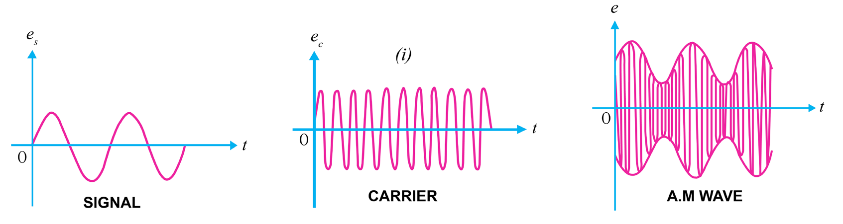
Fig.6. 3 A graphs of amplitude modulation
Note that the amplitudes of both positive and negative half-cycles of carrier
wave are changed in accordance with the signal. For instance, when the signal
is increasing in the positive sense, the amplitude of carrier wave also increases.
On the other hand, during negative half-cycle of the signal, the amplitude of
carrier wave decreases. Amplitude modulation is done by an electronic circuitcalled modulator.
6.2.2 Frequency modulation (FM).
It is a type of modulation, where the frequency of the carrier wave is changed
in accordance with the intensity of signal. The amplitude and the phase shift of
the modulated wave remain the same. The frequency variations of carrier wave
depend upon the instantaneous amplitude of the original signals. The carrier
frequency increases and decreases respectively to its positive and negative peakvalues as the voltage of the original signal seem to approach its peak values.
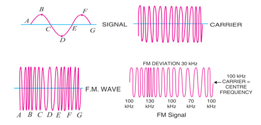
Fig.6. 4: Process of FM transmission
Comparison of amplitude modulation and frequency modulation
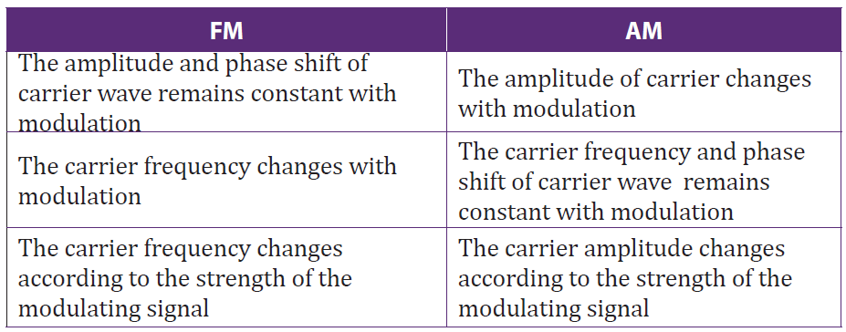
Table 6. 1: Comparison between FM and AM
6.2.3 Short wave (SW)
A short wave is any wave whose frequency ranges between 300 kHz and 3 MHz.
In transmission, these waves are used for very long distance communication as
their bands can be reflected or refracted from the ionosphere by an electricallycharged layer with atoms in the atmosphere.
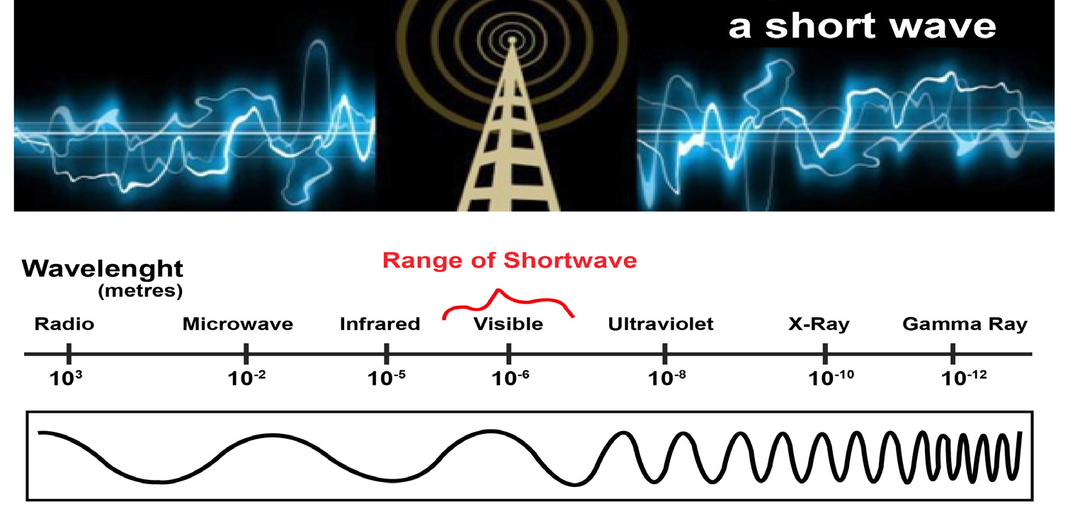
Fig.6. 5: Short wave illustration
The short waves directed at an angle into the sky can be reflected back to Earth at
great distances, beyond the horizon. This called sky wave or skip propagation.
These waves are used for radio broadcasting of voice and music to shortwave
listeners over very large areas; sometimes entire continents or beyond. They
are also used for military communication, diplomatic communication, and twoway
international communication by amateur radios enthusiasts for hobby.
6.2.4 Medium wave (MW)
Medium wave (MW) is the part of the medium frequency (MF) radio band
used mainly for AM radio broadcasting. It is the original radio broadcasting
band, in use since the early 1920’s. It is typically used by stations serving a local
or regional audience. At night, medium wave signals are no longer absorbed by
the lower levels of the ionosphere, and can often be heard hundreds or even
thousands of miles away.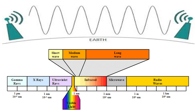
For Europe the MW band ranges from 526.5 kHz to 1606.5 kHz, using channels
spaced every 9 kHz, and in North America an extended MW broadcast band
ranges from 525 kHz to 1705 kHz, using 10 kHz spaced channels.
6.2.5 Checking my progress
1. In transmission, the range of short waves are between
a. Radio wave and microwave
b. X-rays and gamma rays
c. Infrared and visible light
d. Infrared and ultraviolet
2. Where Short waves can be used?
3. Explain what is meant by Medium wave (MW)
4. Distinguish between Amplitude modulation and frequency modulation
6.3 CARRIER WAVE AND MODULATOR
6.3.1 Concept of carrier wave modulation
ACTIVITY 6.3: Modulation techniquesWhat are applications of such a system shown in the below figure?
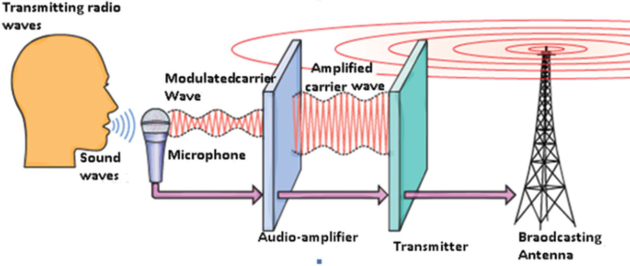
Fig.6. 6: Radio wave transmission
Observe the mechanism above (Fig.6.6) and answer to the following
questions
1. Analyze the provided figure and explain the transmission process
used there.2. What are applications of such a system shown in the above figure?
Modulation is the process of varying the characteristics of carrier signal with
the modulating signal or modulation is defined as the superimposition of low
frequency baseband signal (modulating signal) over high frequency carrier
signal by varying different parameters of the carrier signals (see Fig.6.6). Based
on the types of parameters that are varied in proportion to the baseband (low
frequency) signal, modulation is of different types. In digital modulation, the
message signal is converted from analog into digital. In digital modulation
techniques, the analog carrier signal is modulated by discrete signal. The carrier
wave is switched on and off to create pulses such that signal is modulated.
Low frequency signal (Baseband) communication is not commonly used for
distance communication. Low frequency baseband signals, having low energy,
if transmitted directly will get distorted. So baseband signal must be modulated
with high frequency signal to increase the range of transmission.
6.3.2 Checking my progress
1. In………transmission, the carrier signal modulated so that its amplitude
varies with the changing amplitudes of the modulating signal
a. AM c. FM
b. PM d. None of the above?
2. Distinguish between analog signal and digital signal?
3. What is meant by carrier wave in telecommunication?4. What is the application of a carrier wave in a telecommunication system?
6.4 OSCIALLATOR, RADIO FREQUENCY AMPLIFIER AND
POWER AMPLIFIER
ACTIVITY 6.4: Investigating what is an oscillator and a radio
frequency amplifier
Make an intensive research on the properties and function of an
oscillator and radio frequency amplifier. According to your findings,
answer to the following questions:
1. Explain a radio frequency amplifier and state its importance in
telecommunication?
2. What do you understand by an oscillator in telecommunication
system? Discus its importance?3. Describe other uses of oscillator and radio frequency amplifier.
6.4.1 Oscillator
Oscillators are electronic circuits that produce a periodic waveform on its
output with only the DC supply voltage as an input. The output voltage can
be either sinusoidal or non-sinusoidal, depending on the type of oscillator, thus,
the outputs signals can be sine waves, square waves, triangular waves, and sawtooth waves.
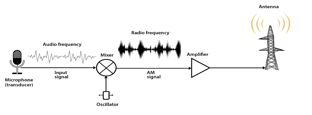
Fig.6.7: Basic function of oscillator and radio frequency amplifier in telecommunication system
The oscillation in any circuit will depend on the following properties:
• Amplification of the used amplifier
• A frequency determining device (receiver/ transmitter)
• Signal regeneration (Positive feedback)
Factors which may fluctuate the operating frequency
• Long time of operation
• Heat that is generated along the operation
• Operating point of the active elements
• Frequency dropper elements (capacitors, inductors)
• Change in total opposition faced by the alternating current (impedance)
Oscillators may be classified in three ways, including:
a. The design principle used where we have a positive and a negative
feedback oscillators,
b. The frequency range of the signal over which they are used:
• Audio Frequency (AF) oscillators (frequency range is 20 Hz to 20 kHz)
• Radio Frequency (RF) oscillators (frequency range is 20 kHz to 30
MHz)
• Video Frequency oscillators (frequency range is dc to 5 MHz)
• High Frequency (HF) oscillators (frequency range is 1.5 MHz to 30
MHz)
• Very High Frequency (VHF) oscillators (frequency range is 30 MHz to
300 MHz)
c. The nature of generated signals where we have:
• Sinusoidal Oscillators: These are known as harmonic oscillators and
are generally LC tuned-feedback or RC tuned-feedback type oscillator
that generates a sinusoidal waveform which is of constant amplitude
and frequency.
• Non-sinusoidal Oscillators: These are known as relaxation oscillators
and generate complex non-sinusoidal waveforms that changes very
quickly from one condition of stability to another such as square-wave,triangular-wave or sawtooth-wave type waveforms
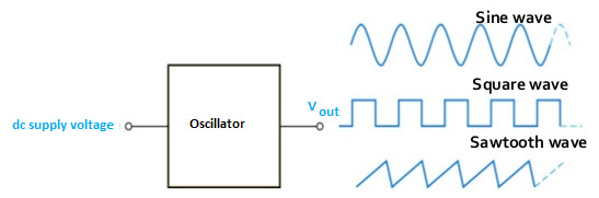
Fig.6. 8: Types of signals output of an oscillator
The oscillators have a variety of applications. In some applications we need
voltages of low frequencies, in others of very high frequencies. For example
to test the performance of a stereo amplifier, we need a signal of variable
frequency in the audio range (20 Hz-20 KHz). Next to amplifiers, oscillators
are the most important analog circuit block. Oscillators can be found in almost
every imaginable electronic system. For example all radio receiving systems
must have a local oscillator. All transmitting systems require oscillators to
define the carrier frequency. Similarly, most digital systems are clocked and
require a master clock oscillator to operate. Signal sources, which are essential
for testing electronic systems, are also precise oscillators whose frequency and
amplitude can be accurately set according to the requirement.
6.4.2 Radio frequency amplifier
An amplifier is an electronic device which can increase the amplitude or the
power of the input signal to its input parts, without the needs of modifying
the form of that signal. Mostly, these devices are used in telecommunication,
especially in receivers. Any amplifier has an active element, more often
transistors, though there may exist also resistors, inductors and capacitors.
Classes of amplifiers
There exist two classes: Capacitor coupled amplifiers and transformer
coupled amplifiers. The two are used in multistage amplifiers, that is when
we connect two stage amplifiers using a capacitor and when we connect two
stages amplifiers using a transformer, we get a capacitor coupled amplifier and
a transformer coupled amplifier respectively.
Characteristics of RF amplifier
1. It may require or not a wide bandwidth signal to amplify
2. The output signal from the RF amplifier may or not be linear
3. They require to operate at a narrow bandwidth
4. They can use filters to reduce bandwidth5. To tune the circuit, the resonant frequency is set to
All electronic devices have an inductive reactance and capacitive reactances. The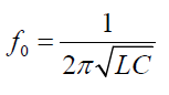
latter are vary as the frequency fluctuates. Normally, as the frequency increases,
the inductive reactance increases but capacitive reactance decreases. Then
the circuit will be called self-resonate at point, where the two characteristics
mentioned above become equal.
In signal processing, we need to realize as many operations as possible so
that we arrive to a signal that fits the transmission standards. The signal to be
modulated is referred to as a baseband signal. The carrier signal needs to be a
higher frequency than the baseband. A RF amplifier is a device which amplifies
the baseband signal. However, devices such as Oscillators, Mixers, Multipliers
and frequency synthesizers can be used to meet the above conditions.
6.4.3 Power Amplifier
Signals are amplified in several stages (Fig.6.9). The initial stages are small
signal amplifiers, they are designed to give good voltage gain, so they are called
voltage amplifiers. At the final stage, the signal becomes large, the large-signalamplifier is called power amplifier, as it is designed for good power gain.
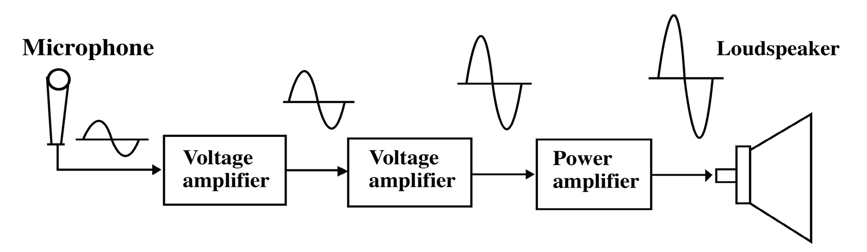
Fig.6. 9 The functioning mechanism of power amplifier
The Fig.6.10 shows that the power amplifiers are classified according to the
conduction angle they produced. Conduction angle measures the portion of
the input cycle that is reproduced at the output of a power amplifier. If the
conduction angle is 360°, which means that all of the input cycle is reproduced,the amplifier is called class A amplifier.
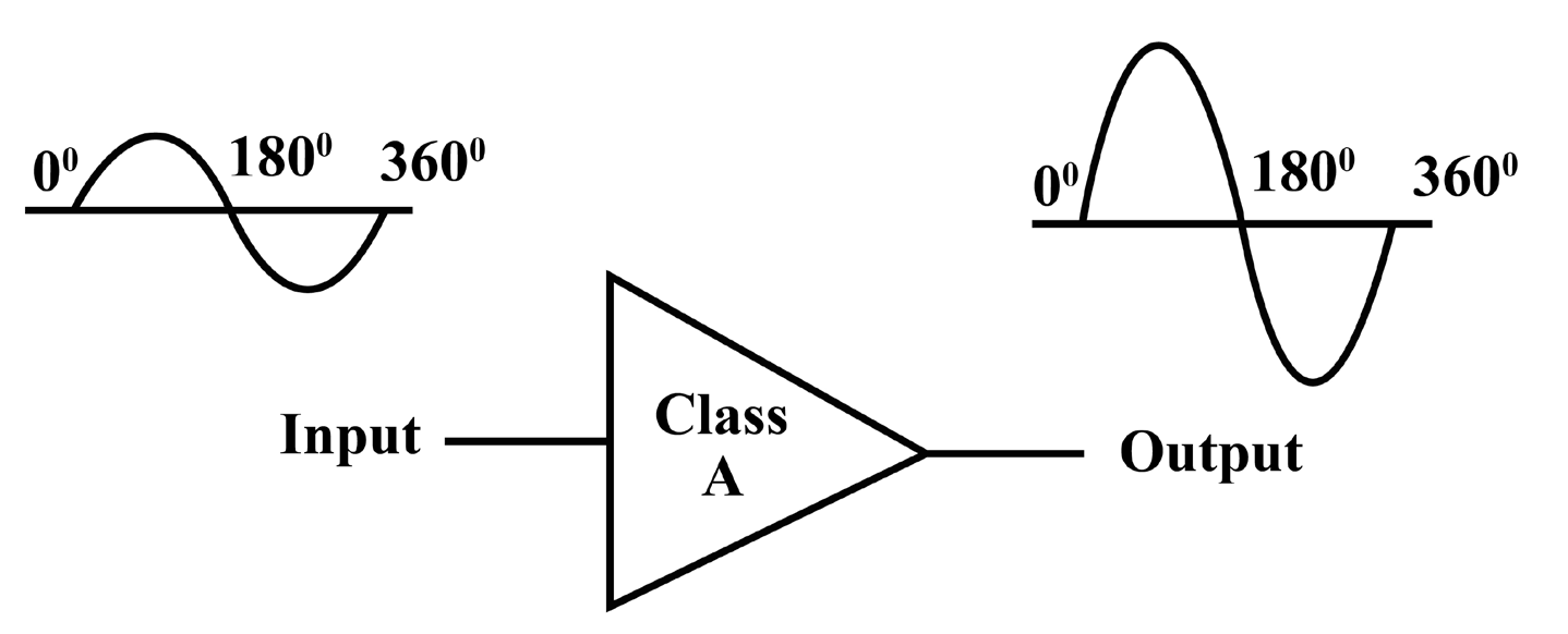
Fig.6. 10: The conduction angle of power amplifier
Every amplifier has a DC equivalent circuit and an AC equivalent circuit.
Because of this, it has two load lines : a Dc load line and an AC load line.
6.4.4 Checking my progress
1. State the classifications of oscillators according to Frequency Band of
the Signals
2. Explain what is mean by Oscillator
3. The figure is about transmission of signals in telecommunication. Studyit carefully and label it.
6.5 ANTENNAS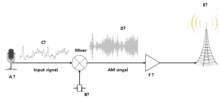
ACTIVITY 6.5: Defining types of antennas
Observe clearly the images on the fig. 6.11 below and answer thequestions that follow:
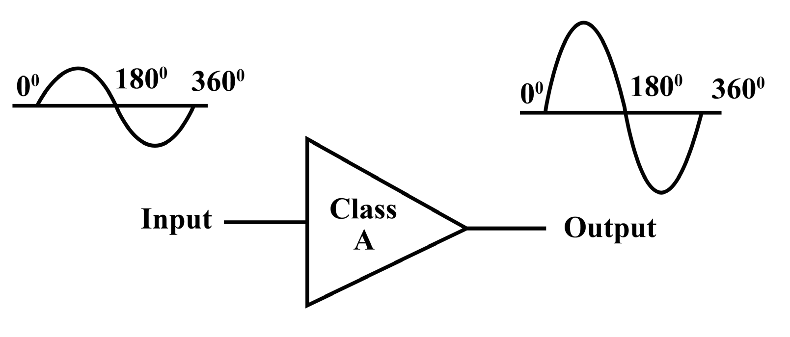
Fig.7. 11 Different types of antenna
1. Describe the different the types of antenna shown in the Fig.7.11
above.
2. Discuss other different types of antenna you know.
3. Discuss and explain the function principle of an antenna.
An antenna or aerial is an electrical device connected (often through a
transmission line) to the receiver or transmitter which converts electric power
into radio waves, and vice versa. It is usually used with a radio transmitter
or radio receiver. In transmission, a radio transmitter supplies an oscillating
radio frequency electric current to the antenna’s terminals, and the antenna
radiates the energy from the current as electromagnetic waves (radio waves).
In reception, an antenna intercepts some of the power of an electromagnetic
wave in order to produce a tiny voltage at its terminals, which is fed to a receiver
to be amplified.
Antennas are essential components of all equipment which are used in radio.
They are used in broadcasting systems, broadcast television systems, two-way
radio systems, communications receiver’s systems, radar systems, cell phones
systems, and satellite communications systems, garage door openers systems,
wireless microphones systems, Bluetooth enabled devices systems, wireless
computer networks systems, baby monitors systems, and Radio Frequency
Identification (RFID) tags systems on merchandise etc.
6.5.1 Types of antennas
There are a very large variety of antennas used in telecommunication. Here we
can discuss at least four types of antenna among others.
Wire antennas
The wire antennas are dipole, monopole, loop antenna, helix and are usually
used in personal applications, automobiles, buildings, ships, aircrafts and supercrafts.
Aperture antennas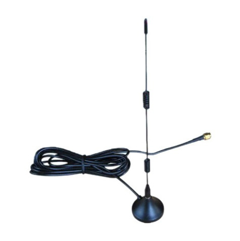
These are horn antennas and waveguide opening and they are usually used inaircrafts and space crafts because they are flush-mounted.
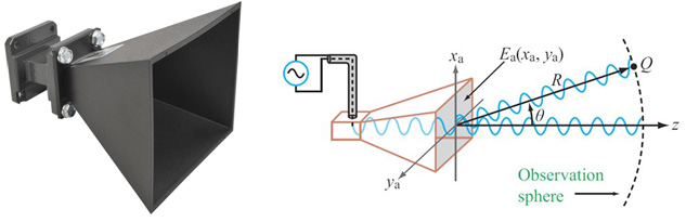
Fig.6. 13: A horn antenna with aperture field distribution
Reflector antennas
These are parabolic reflectors and corner reflectors and they are high gain
antennas usually used in radio astronomy, microwave communication andsatellite tracking.
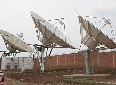
Fig.6. 14: Reflector antenna
Array antennas
These are also called Yagi-Uda antennas or micro-strip patch arrays or
aperture arrays, slotted waveguide arrays. They are suitable for very high gainapplications with added advantage, such as, controllable radiation pattern.
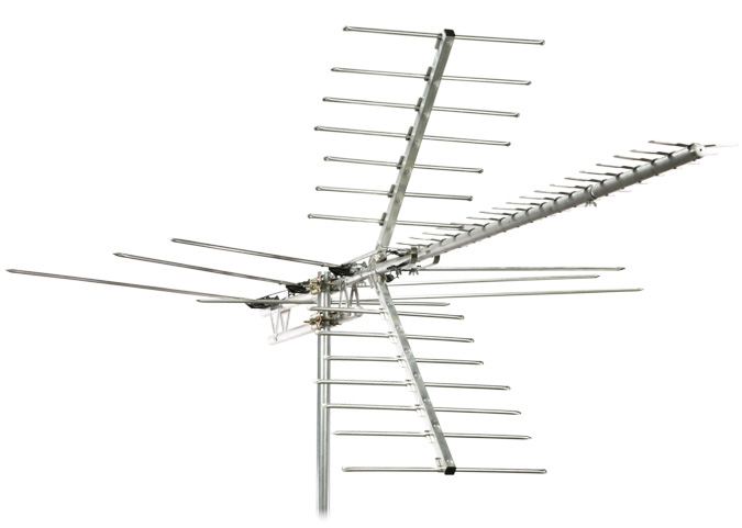
Fig.6. 15: Array antenna.
6.5.2 Checking my progress
1. What is meant by an antenna in telecommunication system?2. State and explain at least two types of antenna
6.6 BLOCK DIAGRAMS OF TELECOMMUNICATIONACTIVITY 6.6: Investigating communication block
Information: Information is any entity or form that resolves uncertainty or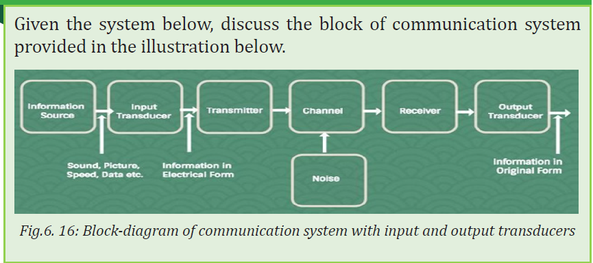
provides the answer to a question of some kind. It is thus related to data and
knowledge, as data represents values attributed to parameters, and knowledge
signifies understanding of real things or abstract concepts. Message: A message
is a term standing for information put in an appropriate form for transmission.
Each message contains information. A message can be either analog message
(a physical time variable quantity usually in smooth and continuous form) or
a digital message (anordered sequence of symbols selected from finite set of
elements) as shown in Fg.6.19.
• Analog message: a physical time-variable quantity usually in smooth
and continuous form.
• Digital message: ordered sequence of symbols selected from finite set
of elements.
A signal is a mathematical function representing the time variation of a physical
variable characterizing a physical process and which, by using various models,
can be mathematically represented. In telecommunication, the message is also
known as a signal and the signal is transmitted in an electrical or voltage form.( i.e Signal ≈ Message)
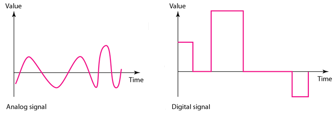
Fig.6. 17: Analog signal and digital signal representation diagram
COMPARISON OF AN ANALOG SIGNAL TO A DIGITAL SIGNAL
As discussed in the previous section, we can have the summary of differencesbetween analog signal and digital signal (see Table 6.2)
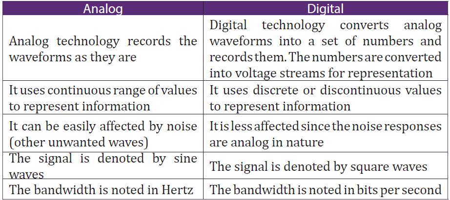
Table 6. 2: Comparison of an analog signal to a digital signal
SOME ELEMENTS OF BLOCK DIAGRAM OF TELECOMMUNICATION
1. Transmission channel which is the electric medium that bridges the
distance from source to destination
2. The receiver to convert the received signal in a form appropriate for the
output transducer after amplifying, filtering, demodulating and decoding it
3. Output transducer to convert the output electrical signal the desired
message form
4. Modulation is defined as the process by which some characteristics (i.e.
amplitude, frequency, and phase) of a carrier are varied in accordance with
a modulating wave.
5. Encoding is the process of coding the message and changes it in the
language understandable by the transmitter. This operation is realized at
the transmitting end
6. Demodulation is the reverse process of modulation, which is used to
get back the original message signal. Modulation is performed at the
transmitting end whereas demodulation is performed at the receiving end
7. Decoding is the reverse process of encoding to retrieve the original
message and make it human understandable message. It is realized at the
receiving end
8. Antennas which are aerials used to transmit and receive the signals.
9. The oscillators which are the sources of carrier signals which are used to
modulate and help the original signal to reach the destination
10. The signal normally, must be raised at a level that will permit it to reach itsdestination. This operation is accomplished by amplifiers
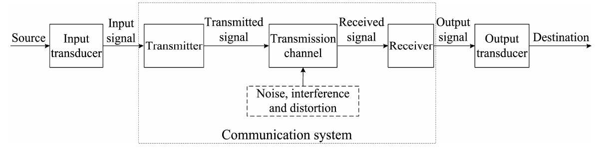
Fig.6. 18: Block diagram of telecommunication
6.6.1 Simple radio transmitter
A radio transmitter consists of several elements that work together to generate
radio waves that contain useful information such as audio, video, or digital
data. The process by which a radio station transmits information is outlined inFig. 6.21.
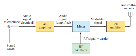
Fig.6. 19: Block diagram of a radio transmitter
• Power supply: Provides the necessary electrical power to operate the
transmitter.
• The audio (sound) information is changed into an electrical signal
of the same frequencies by, say, a microphone, a laser, or a magnetic
read write head. This electrical signal is called an audio frequency
(AF) signal, because the frequencies are in the audio range (20 Hz to
20 000 Hz).
• The signal is amplified electronically in AF amplifier and is then mixed
with a radio-frequency (RF) signal called its carrier frequency, which
represents that station. AM radio stations have carrier frequencies
from about 530 kHz to 1700 kHz. Today’s digital broadcasting uses the
same frequencies as the pre-2009 analog transmission.
• The Modulator or Mixer adds useful information to the carrier wave.
The mixing of the audio and carrier frequencies is done in two ways.
- In amplitude modulation (AM), the amplitude of the highfrequency
carrier wave is made to vary in proportion to the
amplitude of the audio signal, as shown in Fig.6.3. It is called
“amplitude modulation” because the amplitude of the carrier is
altered (“modulate” means to change or alter).
- In frequency modulation (FM), the frequency of the carrier wave
is made to change in proportion to the audio signal’s amplitude,
as shown in Fig.7.4. The mixed signal is amplified further and
sent to the transmitting antenna (Fig.6.13.C), where the complex
mixture of frequencies is sent out in the form of EM waves.
• Amplifier: Amplifies the modulated carrier wave to increase its power.
The more powerful the amplifier, the more powerful the broadcast.
In digital communication, the signal is put into digital form which modulates the
carrier. A television transmitter works in a similar way, using FM for audio and
AM for video; both audio and video signals are mixed with carrier frequencies.
6.6.2 Simple radio receiver
A radio receiver is the opposite of a radio transmitter. It uses an antenna to
capture radio waves, processes those waves to extract only those waves that are
vibrating at the desired frequency, extracts the audio signals that were added
to those waves, amplifies the audio signals, and finally plays them on a speaker.
Now let us look at the other end of the process, the reception of radio and TV
programs at home. A simple radio receiver is graphed in Fig. 6.22. The EMwaves sent out by all stations are received by the antenna.
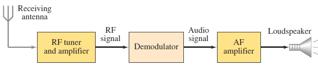
Fig.6. 20 Block diagram of a simple radio receiver
The signalantennadetect and send the radio waves,to the receiver are very
small and contain frequencies from many different stations. The receiver uses
a resonant LC circuit to select out a particular RF frequency (actually a narrow
range of frequencies) corresponding to a particular station.
A simple way of tuning a station is shown in Fig.6.23. When the wire of antenna
is exposed to radio waves, the waves induce a very small alternating current inthe antenna.
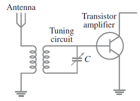
Fig.6. 21: Simple tuning stage of a radio.
A particular station is “tuned in” by adjusting the capacitance C and/or
inductance L so that the resonant frequency of the circuit equals that of the
station’s carrier frequency. R.F. Amplifier: A sensitive amplifier that amplifies
the very weak radio frequency (RF) signal from the antenna so that the signal
can be processed by the tuner.
R.F. Tuner: A circuit that can extract signals of a particular frequency from a
mix of signals of different frequencies. On its own, the antenna captures radio
waves of all frequencies and sends them to the RF amplifier, which dutifully
amplifies them all. Unless you want to listen to every radio channel at the same
time, you need a circuit that can pick out just the signals for the channel you
want to hear. That’s the role of the tuner.
The tuner usually employs the combination of an inductor (for example, a coil)
and a capacitor to form a circuit that resonates at a particular frequency. This
frequency, called the resonant frequency, is determined by the values chosen
for the coil and the capacitor. This type of circuit tends to block any AC signals
at a frequency above or below the resonant frequency.
You can adjust the resonant frequency by varying the amount of inductance
in the coil or the capacitance of the capacitor. In simple radio receiver circuits,
the tuning is adjusted by varying the number of turns of wire in the coil. More
sophisticated tuners use a variable capacitor (also called a tuning capacitor) tovary the frequency.
6.6.3 Wireless Radio Communication
Let us now discuss the basic principles of wireless radio communications.
We shall mainly concentrate on the principle of amplitude modulation and
demodulation. The simplest scheme of wireless communication would be
to convert the speech or music to be transmitted to electric signals using a
microphone, boost up the power of the signal using amplifiers and radiate the
signal in space with the air of an antenna. This would constitute the transmitter.
At the receiver end, one could have a pick-up antenna feeding the speech ormusic signal to an amplifier and a loud speaker. (See Fig.6.24)

Fig.6. 22 Wireless radio communication
The above scheme suffers from the following drawbacks:
i. EM waves in the frequency range of 20 Hz to 20 kHz (audio-frequency
range) cannot be efficiently radiated and do not propagate well in space.
ii. Simultaneous transmission of different signals by different transmitters
would lead to confusion at the receiver.
In order to solve these problems; we need to devise methods to convert or
translate the audio signals to the radio-frequency range before transmission and
recover the audio-frequency signals back at the receiver. Different transmitting
stations can then be allotted slots in the radio-frequency range and a single
receiver can then tune into these transmitters without confusion.
The frequency range 500 kHz to 20 MHz is reserved for amplitude-modulated
broadcast, which is the range covered by most three band transistor radios. The
process of frequency translation at the transmitter is called modulation. The
process of recovering the audio-signal at the receiver is called demodulation. Asimplified block diagram of such a system is shown in the below figure.
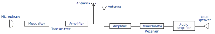
Fig.6. 23 Block diagram of radio transmitter and receiver
6.6.4 Checking my progress
1. What is the importance of power amplifier in simple radio transmitter.
2. What do you understand by the following terms.
3. Analog message
4. Digital message
5. Draw a circuit diagram of a simple radio receiver
END UNIT ASSESSMENT 6
A. Multiple choices
1. One of the following is used for satellite communication
a. Radio waves c. Microwaves
b. Light waves d. All of these
2. Amplitude –modulated radio waves are received by a tuned radiofrequency
( trf) Receiver. The receiver has a suitable detector
circuit in order to
a. Amplifier the carrier waves
b. Amplifier the audio-frequencies carried
c. Rectifier the carrier waves
d. detect the carrier waves
e. Transfer the audio-frequencies to the radio-frequency
amplifier
B. Structured questions
3. What do you understand by the following terms?
a. Amplifier
b. Modulator
4. What is meant by telecommunication system?
5. Draw a labeled diagram showing the elements of radio transmitter
C. Essay question
6. Recently, the government of Rwanda decided to replace analog
system of communication by digital system of communication.
Debate about this government policy
7. Explain briefly positive impact of telecommunication in developmentof a country like Rwanda.