INTRODUCTORY ACTIVITY
Consider the Company AMAHORO Ltd with departments like Accounting and Finance,
Human Resource and ICT. Each department has its own employees who are each
identified by Id, First Name, Surname, Salary, telephone number and Address.
Suppose that this Company uses the file approach to keep information of its employees,
where each department has its own file to store necessary information. The payroll file
is managed in Accounting and Finance departments and a record of an employee’s
salary is described by Employee Id, First name, Surname and Salary Amount.
Assume that a new column for the date of recruitment is to be added to the payroll and
there is a request in Accounting and Finance departments to retrieve all the employees’
details whose salaries are greater than 100,000 FRW. One employee finds that his/her
first name was not correctly written on the payroll.
Since each department has own separate file, it is difficulty to the Human Resource
Manager to access all the files and make any modification any time he/she wants.
1. Discuss whether the approach described above is well designed?
2. Describe the difficulties each department may encounter?
3. Discuss and Suggest the CEO of this Company the best and efficient
approach to be used for overcoming all difficulties.
5.1 INTRODUCTION
Sometimes ago, organizations usually stored information in a way which was with
many risks of being lost, damaged, corrupted and not well organized. It was kept
inTraditional File Processing (TFP) which presented many disadvantages.
Nowadays, well-designed database arises to overcome those problems and saves the
time in the long run for the user. It is facilitated by a Database Management Systems
(DBMS). The design of such database presents 3 main levels called “
Database designlevels”. These levels help to make easy the understanding and the management of a
database. Later on, it will not be very difficult for the software developer to use that
database.
ACTIVITY 5.1
Read the following scenario and give answers to the asked questions
Your school needs to keep information securely of its teachers, students, combinations
and courses. Each teacher is characterized by its identity number, first name, second
name, salary, qualification, address, telephone number and email.
The Combination is identified by its Id and Name. The student identified by its Id, First
Name, Surname, Address, School fees, Contact Number, Combination Id, Class and
Course is identified by the Course Id, Title, Combination,
From the above,
1. Discuss the data types for the attributes identifying entity Teacher,
Combination, Student and Subject.
2. Describe the relationships between entities: Teacher, Combination,
Student and Subject?
5.1.1 The conceptual level
The conceptual levelis concerned with concept(abstract), an idea of what something
is or how it works; something formed in the mind; a mental image.
There exist different models used for the conceptual level to represent all the data
elements likely to belong to the database but the most used is the Entity- Relationship
Model (ERM) It uses the main concepts like entities, attributes and relationships.
An entity represents a real-world object such as an employee or a project and has
attributes that represent properties such as EmpId, FirstName, Surname, Address
and Birthdate. A relationship represents an association or a link among entities.
For example, when an employee works on many projects, a relationship exists
between the employee and each project.
If an employee is identified by EmpId, FirstName, Surname, Address and Birthdate
while a project is identified by its ProjectId and ProjectName, the diagram
representing the Entity Relationship is the following.
5.1.2 The logical level
The logical level makes it possible to create relational structures enabling us to put
into practice the conceptualization by imagining a relational Database Management
System (DBMS). It is characterized by clear and sound reasoning. At this level there
exist different models like network data models and hierarchical data models and
relational model. Currently the mostly used is the Relational model. In the case of
database having Employee and Project entities the relational model is represented
by the following tables.
5.1.3 Physical level
The physical level is concerned with how data will be encoded and stored. It
consists of the practical application (Database Management Systems - DBMS) of
all the preceding theories by using computers together with its software to create
a database. It deals with storage and processing performance, volumetric (time &
space), partitioning and distribution.
The most known development tools to use are MS Access, MySQL (My Structured
Query Language), SQL (Structured Query Language) and NoSQL.
Application Activity 5.1
Galleries keep information about artists, their identification, their names, birth address,
age, and art style. For each piece of artwork/product, the artist, the production year, its
title, its type of art (e.g., painting, filmmaking, photograph, crafts, sculpture, drawings,
etc), and its price in FRW must be stored. Pieces of artwork are also classified into
groups of various kinds, for example, Rwandan art, 19th-century Art(old testament,
the French art,Haloween,etc), works by Pablo Picasso; a given piece may belong to
more than one group.Each group is described by an id and name.
Finally, galleries keep information about customers. For each customer, galleries keep
that person’s unique identification, full name, and address, total amount of FRW spent
in the gallery, the artists and groups of art that the customers tend to appreciate.
Draw conceptual, logical and physical levels for the above described database.
Example: SCHOOLS Database
• A View for registrar office
Course info (coursid:string,enrollment:integer)
• The conceptual schema:
Students(studid: string, name: string, login:string, age: integer, gpa:real)
Courses(coursid: string, ccoursname:string, courcredits:integer)
Enrolled(sstudid:string, coursid:string, grade:string)
• The physical schema:
Relations stored as unordered files.
Index on first column of Students.
Learning Activity 5.2.
Read the following scenario and give answers to the asked questions
At Groupe Scolaire Kinazi, the management of students’ information is not
computerized. The Headteacher is looking for a solution so that the database of
students can be managed digitally and hence speed up the production of transcripts
and the search of information when they are requested for. If you are given the task to
design that database, how are you going to proceed?
1. Discuss the different steps to use so that you can succeed the
assignment.
2. Discuss the financial savings made by the school when using
computerized application instead of manual system.
The most important thing to do to start designing a database is to think ahead.
When a case that needs a database creation is presented, before to switch on the
computer, it is better to think about the type of information to work with and the
types of questions that the database should answer, what information needs to
be stored and what specifically are the links between them. The next phases are
to verify all requirements specifications, to represent the data with diagram, and
to plan the database, here are three rules of
database design: Rule 1-Plan; Rule
2-Plan; Rule3-Plan.
When data is more complex, there are more needs to plan. Even the simplest
database should be thought through on paper before being created in any tool such
as Microsoft Access, SQL, MySQL, etc.
A well-designed database performs well and adapts to future needs by giving users
access to essential information. Poor planning often results in a database that fails
to meet overlooked needs.
In planning the database, regardless of its size and complexity the following basic
steps are used:
1. Investigate the information.
2. Identify the objects.
3. Model the objects.
4. Identify the types of information for each object.
5. Identify the relationships between objects.
6. Database optimization through normalization.
7. Data entry and manipulation
5.2.1. Investigate information
Before creating a database, there is a need of good understanding of the problem
that the database is expected to solve. If the database is to replace the traditional
method, file based approach method, then the existing system will give most of the
information needed.
During investing information, there is a need to work with everyone involved in the
existing system to see what is needed from the new database. Gathering techniques
include collect copies of customer information, management reports, and any other
documents that are part of the existing system, because these will be useful in
designing the database and the interfaces.
5.2.2. Identifying the important entities and their attributes
During the process of gathering/investigating information, the key objects or
entities that will be managed by the database must be identified. The object can be
a tangible thing, such as a person (for example student, employee, and patient) or a
product, or it can be a more intangible item, such as a department in an institution,
a Combination in a school. Each distinct item in the database should have a
corresponding table for which column titles are attributes of the entity
5.2.3. Identifying the Relationship Between entities
One of the strengths of an E-R database is the ability to relate or associate information
about various items in the database.
Isolated types of information can be stored separately, but the database can combine
data when it is required. Identifying the relationship between entities in the design
process requires looking at the entities, determining how they are logically related,
and adding relational columns that establish a link from one table to another.
5.2.4. Modeling the objects
As the objects in the system and their attributes are identified, they are recorded in
a way that represents the system visually. They are recorded using Relational model
and Entity Relational model
5.2.5. Identifying the types of information for each object
After identifying the primary objects/entities in the database as candidates for
tables, the next step is to identify the types of information that must be stored for
each object.
These are the columns in the table of the object.
Fields/columns should be kept simple, the more atomic your fields the more flexible
will be your database.
For example, in a database of names and addresses, you would keep each part of
the person’s name as a separate field.
The columns in a database table contain a few common types of information:
Raw data columns
These columns store tangible pieces of information, such as names.
Categorical columns
These columns group the data and store a limited selection of data such as true/
false, married/single/divorced/widowed, Male/Female, etc.
Identifier columns
These columns provide a mechanism to identify each item stored in the database
table. These columns frequently have an id or number in their name, for example,
EmployeeId, StudentId, PersonIdNo and InvoiceNumber. The identifier column is the
primary component.
Relational or referential columns
These columns establish a link between information in one entity and related
information in another entity.
For example, an entity that tracks sales transactions will generally have a link to the
customer’s entity so that the complete customer information can be associated with
the sales transaction.
5.2.6. Database optimization through normalization
One of the most important step to consider when designing a database is database
definition. If tables are not set up properly, it can cause a lot of headaches down
the road the time of extracting/retrieving required data. Understanding the rules
of normalization enforces redundancy elimination and inconsistent dependency in
database designs.
5.2.7. Data entry and manipulation
The goal of data entry is to create data that are valid and well organized to assure
their quality during extraction. Well stored data leads to data consistency.
Application activity 5.2.
5.3. RELATIONAL MODEL
Learning Activity 5.3.
Read the following scenario and give answers to the asked questions
Suppose that School wants to develop an information system in which student studies
in one of the combination and learns different subjects. The system will record details
concerning student, combination and subject.
1. Which properties would you expect to find in each student object?
2. Arrange those properties in tabular form of mxn dimension
5.3.1. Introduction
The relational data model was introduced by C. F. Codd in 1970. Currently, it is the
most widely used data model. It describes the world as “a collection of inter-related
relations (or tables).”
a. Relation
A relation, also known as a table or file, is a subset of the Cartesian product of a list
of domains characterized by a name. You can also think of it this way: an attribute is
used to define the record and a record contains a set of attributes.
The steps below outline the logic between a relation and its domains.
1. Given n domains are denoted by D1, D2 Dn
2. And r is a relation defined on these domains
3. hen r C D1×D2×…×Dn
The following are the key component to know when we are talking about relation:
Relation, Tuple, Attribute, Cardinality, Degree, Primary key, Domain
b. Equivalent Database Concepts
• Relation <=> Table
• Tuple <=> Row or record
• Attribute <=> Column or field
• Cardinality <=> Number of rows
• Degree <=> Number of columns
• Primary key <=> Unique identifier
• Domain <=> Pool of legal values
c. Table
Data is stored in rows and columns. Each Row is known as record and the data items
are known as fields. Tables contain data about one type of item, person or event, for
example:
• a table of patients, a table of a student, a table of teacher, a table of books and
a table of doctor’s appointment
For a book the fields could include:
• Title, Author, ISBN, Publication house
Column
A database stores pieces of information or facts in an organized way. The principal
storage units are called columns or fields or attributes. These house the basic
components of data into which your content can be broken down.
Records
Each row represents a group of related data values, such as a customer or an
employee. A row, or record, is also known as a tuple
Cell
The link/intersection between column and record is known as cell. It also needs to
be available so that they can be reconstituted into their whole form, the basis of all
databases.
A simple table below gives us the clearest picture of how records and fields work
together in a database storage project.
d. Null value
In many situations every row and column will contain data, but there cases where it
makes sense for some columns to not contain a value.
In our example StudentId cannot be null because it is unique but Sex can be null
because it is optional field
e. Degree
The degree is the number of attributes in a table. In our example above in Figure 5.4
the degree is 6.
f. Domain
A domain is the original sets of atomic values used to model data. A domain is a set
of acceptable values that a column is allowed to contain.
For example:
• The domain of Marital Status has a set of possibilities: Married, Single, Divorced,
Widowed.
• The domain of Shift has the set of all possible days: {Monday, Tuesday,
Wednesday, Thursday, Friday, Saturday and Sunday}.
• The domain of Salary is the set of all floating-point numbers greater than 0 and
less than 200,000 FRW.
• The domain of First Name and Surname is the set of character strings that
represents names of people.
g. Datatype
Each field in a record has its own data type. The data types in the fields can be text,
alphanumeric, numeric, and Boolean or date/time.
Table 5.1: Datatype example
Application Activity 5.3.
1. Suppose that a hospital wants to develop system which manages
doctors and patients.
Patients are treated in a ward by the doctors assigned to them. Each patient will be
assigned a single doctor. What fields would you expect to find in each record for a
hospital patient and doctor
2. The following table describes information about employees, study it
and answer the following questions :
a. Using correct terminology, identify and describe all the components of
employee table.
b. What is the possible domain for field EmpId?
c. How many records are shown?
d. How many attributes are shown?
e. Explain the datatype for each field.
5.3.2 Queries in design view
Learning activity 5.4.
Microsoft Access is a database management system from Microsoft that deals with
relational model and it is consisted of the following different views:
a. Layout view
b. Backstage view
c. Design view
d. Datasheet view
Which of the view above contains command buttons that execute operations on entire
databases? Explain its advantages.
Data in a Microsoft Access database is stored in various interlinked tables. A database
also has forms for data entry though you could enter data directly in tables and
queries for manipulating your data and permitting information to be retrieved from
a table. It also allows filtering so only the required records and fields are seen.
Steps for creating database in Microsoft Access
• Open Microsoft Access
• Click on Blank database in the task pane
• Name your database file (say Company) and click the Create button to create
the database.
Steps for creating a table in Microsoft Access-Design View
1. Open an created database in access DBMS
2. Click on create tab from menu bar
3. In table group click on table design icon
4. Fill field names, data type and their descriptions
Data in an Access table is stored in various fields. Those fields have different properties
such as fieldname, size and data types as shown in the figure below:
Steps for creating relationship between created tables
1. Open a created database in access DBMS
2. Click on database tools tab from menu bar
3. In relationships group click on relationships icon then the relationships
panel will be displayed
4. Select a table name and click on add button
5. Repeat step 4 to all table you want to use
6. Click on design tab from menu bar
7. In tools panel click on edit relationship icon
8. On opened window click on create new button
9. Select the table names and their columns that you want to join
10. Click on ok button
11. Repeat 8, 9, and 10 to all pair table to be joined
After creating a table, enter the data. Note that there are various methods to create
tables in Access, such as by using Table Wizard, Datasheet view or by importing
tables, but this Unit restricts only to Design view.
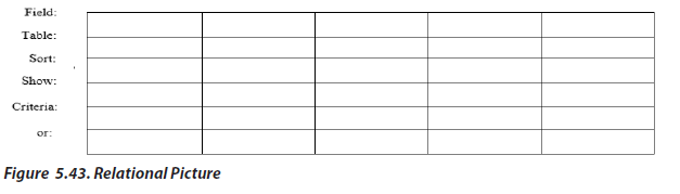
Steps for creating a query using design view-Query by example
Creation of a query in design view has three rows, one to sort the fields, the other
to specify whether or not to display a field, and the last to specify some criteria to
select the records.
1. Click on Create tab of menu from bar
2. In queries grout click on query Design icon
3. Select tables to use then click on Add button
4. In Query Type group select a query commend to be used, Example Select
5. In query panel select the table names and field names you want to select
in different tables
6. Check in show row ender the select item if you want to display them on
output at run time
7. Rename the created query
8. In Result group of menu bar click on Run icon
After the above steps you will get a table containing the selected items as shown in
the examples below:
Query 1: Company leader wants to display onlyEmpId, Fullname (sorted is ascending
order) and salary for all employees.
1. Select EmpId, EmpId, FullName, Salary and check them
2. Select Sort by Ascending on FullName
Output:
Query2: The CEO wants to see only EmpId and FullNames where Salary is less or
equal to 240000.
Select EmpId, EmpId , FullName and check them
Set criteria and uncheck Salary field
Query 3: The following search condition was entered using a query design view
(Query by example) grid:
What will be displayed?
Output:
5.3.3 Dynamic queries using parameter
A parameter is a piece of information you supply to a query right as you run it.
Creating a parameter query
Creating a parameter is similar to adding a normal criterion to a query:
1. Create a select query, and then open the query Design view.
2. In the Criteria row of the field you want to apply a parameter to, enter the
text that you want to display in the parameter box, enclosed in square
brackets.
For example, [Enter the Doj:]
3. Repeat step 2 for each field you want to add parameters to.
When you run the query, the prompt appears without the square brackets.
Fill in the value you’re looking for, and then click OK.
Specify parameter data types
To specify the data type for parameters in a query:
1. With the query open in Design view, on the Design tab, in the Show/Hide
group, click Parameters.
2. In the Query Parameters box, in the Parameter column, enter the prompt
for each parameter you want to specify a data type for.
Make sure that each parameter matches the prompt that you used in the Criteria
row of the query design grid.
3. In the Data Type column, select the data type for each parameter.
Application Activity 5.4.
The database WORLD is composed of one table called WORLDCITIES Figure 5.14.
which stores information about World Cities. Use it to answer asked questions
1. The query-design view grid below selects all Cities from America where
Population is greater than 8 million.
Figure 5.13 QBE grid to display Name of city located in America having population >8M
Show what would be the output.
2. Copy and Complete the query design view grid below to select and
show Name_of_city where Population is greater than to 13 and Area is
equal to 1590.
5.4. ENTITY-RELATIONSHIP MODEL
5.4.1. Introduction
Learning Activity 5.5.
A School needs to store information about Teacher (identified by TeacherId, FirstName,
Surname, Salary, Qualification, Address, Contact); Combination (identified by
CombinationId, CombinationName),Student (identified by StudentId, FirstName,
Surname, Address, Schoolfees, ContactNumber) and Subject (identified by subjectId,
SubjectTitle).
Discribe the logical relationships between objects Teacher-Student, Teacher-
Combination, Student-Combination and Teacher-Subject??
The entity relationship (ER) data model has existed for over 35 years. It is well suited
to data modelling for use with databases because it is fairly abstract and is easy to
discuss and explain. ER models are readily translated to relations. ER models, also
called an ER schema, are represented by ER diagrams.
ER modelling is based on two concepts:
• Entities, defined as tables that hold specific information (data)
• Relationships, defined as the associations or interactions between entities
5.4.2. Entity Relationship Diagram
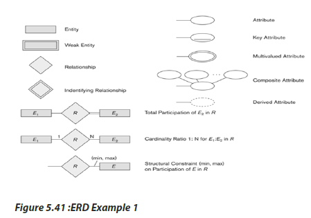
The ER diagram is used to represent the conceptual database schema. In ER diagram:
Entity, Attributes and Relationships form the components of ER Diagram and there
are defined symbols and shapes to represent each one of them.
1. Entity
A rectangle represents an entity set.
2. Relationships between Entities
A diamond represents a relationship.
3. Entity Types
• Entity types ->boxes
• Weak entity type -> double box
Entity types are similar to classes; they describe potential objects (entities) that will
appear in the database. Weak entity types describe dependent entities, entities that
depend on other entities for identity.
4. Attribute
An ellipse represents an attribute (Property).
5. Link between attribute and entity set
Lines represent linking of attributes (properties) to entity sets.
5.4.4. Entities and entity sets
An entity set is a set of entities of the same type that share the same properties. A
noun is used to represent an entity set. An entity is an instance of an entity set.
For example, an entity can be:
• Concrete (TEACHER or STUDENT)
• Insubstantial (GRADE)
• An occurrence (EXAM)
5.4.5. Attributes
A characteristic of an entity, for example First name, Last name and Age. An attribute
is a data item that describes a property of an entity set. Attributes determine, explain,
or categorize an entity set. Attributes have values, which can be of different data
types such as numbers, character strings, dates, images, sounds, and so on. In a
physical model, an attribute is a named column in a table. Each table has a list of
attributes (or columns).
The types of attributes are:
Simple (atomic) attribute – This type of attribute has a single component. It is called
single-valued attribute. For example, the Gender attribute has a single component
with two values.
In the COMPANY database, an example of this would be: Name = {John} ; Age = {23}
Composite attribute – A composite attribute consists of many components.
For example, the Name attribute has the components Last name and First name. So
this would be written as → Name = {KAGABO+Peter}
Address may consist of Province and District, Number, Avenue. So this would be
written as → Address = {KG +‘14’ + ‘Av’}
Single valued attribute – This type of attribute has one value for one entity. For
example, the Title attribute has a single value for each teacher.
Multi-valued attribute – A multi-valued attribute has many values for one entity.
An example of a multivalued attribute from the COMPANY database, as seen in
Figure below, are the degrees of an employee: BSc, MSc., PhD.
Derived attribute – A derived attribute has its value computed from another attribute
or attributes.
A derived attribute is not a part of a table from a database, but is shown for clarity or
included for design purposes even though it adds no semantic information; it also
provides clues for application programmers.
An example of this can be seen in Figure below. Age can be derived from the attribute
Birthdate
In this situation, Birthdate is called a stored attribute, which is physically saved to the
database.
Unstable attributes - This type of attribute have values that always change. For
example, the salary of employee.
Mandatory attributes - Mandatory attributes must have a value. For example, in
most businesses that track personal information, Name is required.
Optional attributes - Optional attributes may have a value or be left null; For
example, address of employee
Unique identifier - This type of attribute distinguishes one entity from another.
For example, in a company, you can distinguish between one employee and another
using a EmployeeID.
5.4.6. Keys
An important constraint on an entity is the key. The key is an attribute or a group
of attributes whose values can be used to uniquely identify an individual entity in
an entity set. In the case of Logical Model you use a special approach for unique
identifier.The equivalent concept for unique identifier within Logical Model is a key.
A key is a field or a set of fields that has/have a unique value for each record in
the relation. You need a key to ensure that you do not meet redundancies within a
relation There are several types of keys each having slightly different characteristics:
Super key-is defined as a set of attributes within a table that can uniquely identify
each record within a table. Super Key is a superset of Candidate key.
Candidate key – A candidate key is an attribute or set of attributes that uniquely
identifies a record in a relation. A candidate key is unique and minimal.
It is unique because no two rows in a table may have the same value at any time. It is
minimal because every column is necessary in order to attain uniqueness.
From our Company database example, if the entity is Employee(SerialNo,EmpId,
First Name, Surname, Address, Contact, Birthdate, Salary, Depid), possible candidate
keys are:
• EmpId,
• SerialNo
• FirstName and Surname – assuming there is no one else in the company with
the same full name
• Surname and Depid – assuming two people with the same Surname don’t
work in the same
Department
Composite keys – these keys have multiple attributes.
Using the example from the candidate key section, possible composite keys are:
• First Name and Surname
• Surname and Depid
Primary key – A primary key is one of the candidate keys from a relation. Every
relation must have a primary key. A primary key shall be at least: - Stable. The value
of a primary key must not change or become null throughout the life of the entity.
The primary key is indicated in the ER model by underlining the attribute.
For example, consider an employee record; using the Age field as the primary key
would not be appropriate because the value of the primary key must not change
over time.
It should be Minimal. The primary key should be composed of the minimum number
of fields to ensure the occurrences are unique.
In this case Employee (EmpId, First Name, Surname, Address, Contact, Birthdate,
Salary, Depid), EmpId is primary key
Secondary key
A secondary key is an attribute used strictly for retrieval purposes (can be composite),
for example: Phone and Surname.
Alternate key – An alternate key is any candidate key that is not chosen to be the
primary key. It may become the primary key if the selected primary key is not
appropriate.
Simple keys – these keys have a single attribute.
Foreignkeys – these keys exist usually when there are two or more relations. An attribute
from one relation has to exist in the other(s) relation. A foreign key is a field (or
fields) that points to the primary key of another table. The purpose of the foreign key
is to ensure referential integrity of the data. In other words, only values that are supposed
to appear in the database are permitted
In the Company database example below, Depid is the foreign key
(EmpId, First Name, Surname, Address, Contact, Birthdate, Salary, Depid)
Attributes and Keys
• Key attributes must be unique for each entity
• Keys are used to identify particular entities
• Partial keys are only partially unique used for weak entity types
Entity Types and Attributes
All regular entity types must have a key attribute or set of key attributes, Weak entity
types must have partial keys, Weak entities get part of their key (and part of their
identity) from some related entity.
Nulls
A null is a special symbol, independent of data type, which means either unknown
or inapplicable. It does not mean zero or blank.
Features of null include:
• No data entry
• Not permitted in the primary key
• Should be avoided in other attributes
• It can represent
an unknown attribute value
1. a known, but missing, attribute value
2. a “not applicable” condition
Example of null
Employee Salary table
In this case commission can be left null
Relationship sets
A relationship set is a set of relationships between two or more sets of entities, and
are regularly represented using a verb.
A relationship is an instance of a relationship set and establishes an association
between entities that are related. These relationships represent something important
in the model. Example: an employee works on a project.
A relationship set always exists between two entity sets (or one entity set relating
to itself ). You need to read a relationship set in double sense, from one entity set to
the other.
Relationships representation
Relationships => diamonds
Identifying relationship => double diamond
Relationships indicate a meaningful connection between two entity types,
Relationships may have attributes, but they cannot have key attributes. Identifying
relationships connect a weak entity type to some other entity type indicates where
the weak entity gets a key to complete its own partial key
5.4.7. Degree of a relationship
The degree of a relationship refers to the number of associated entities. The degree of
a relationship can broadly be classified into unary, binary, and ternary relationship.
5.4.7.1. Unary Relationship
The unary relationship is known as recursive relationship.
In the unary relationship the number of associated entities is one. An entity is related
to itself is known as recursive relation.
An example is shown by the following figure:
Roles and Recursive Relations
When an entity set appears in more than one relationship, it is useful to add labels to
the connecting lines. These labels are called roles.
In this example, labels “Husband” and “wife” are referred to as roles.
5.4.7.2 Binary Relationship
In a binary relationship, two entities are involved. Consider the example where each
staff will be assigned to a particular department. Here the two entities are STAFF and
DEPARTMENT.
5.4.7.3. Ternary Relationship
In a ternary relationship, three entities are simultaneously involved. Ternary
relationships are required when binary relationships are not sufficient to accurately
describe the semantics of an association among three entities.
Example
Consider the example of employee assigned a project.
Here we are considering three entities EMPLOYEE, PROJECT, and LOCATION. The
relationship is “assigned-to.” Many employees will be assigned to one project hence
it is an example of one-to-many relationship.
5.4.7.4. Quaternary Relationships
Quaternary relationships involve four entities. The example of quaternary relationship
is “A professor teaches a course to students using slides.” Here the four entities are
PROFESSOR, SLIDES, COURSE, and STUDENT.
The relationships between the entities are “Teaches.”
The degree of relationship, which determines how many instances of an entity relate
to a single instance of another entity is called Cardinality.
5.4.8. Classifications or types of Relationships
Based on cardinality, the different types of relationships that can exist between
entities are:
5.4.8.1. One-to one (1:1)
A single instance of an entity can relate to only one instance of the other entity.It
is the relationship of one entity to only one other entity, and vice versa. It should
be rare in any relational
database design. In fact, it could indicate that two entities
actually belong in the same table. An example from our Company database is one
employee is associated with one spouse, and one spouse is associated with one
employee.
Other Examples:
• A person can have only one passport.
• The relationship between the President and the country is an example of oneto-
one relationship. For a particular country at a given time, there will be only
one President. In general, a country will not have more than one President at
a given time hence the relationship between the country and the President is
an example of one-to-one relationship.
5.4.8.2. One-to-many (1: M)
An instance of one entity can relate to multiple instance of another instance.
The relationship that associates one record of entity A to more than one record of
entity B is called one-to-many relationship.
Example of one-to-many relationship is a country having states.
For one country there can be more than one state hence it is an example of oneto-
many relationship. Another example of one-to-many relationship is parent–child
relationship. For one parent there can be more than one child. Hence it is an example
of one-to-many relationship.
For Example,
• A class has many students.
• The relationship between EMPLOYEE and DEPARTMENT is an example of
many-to-one relationship. There may be many EMPLOYEES working in one
DEPARTMENT. Hence relationship between EMPLOYEE and DEPARTMENT is
many-to-one relationship.
5.4.8.3. Many-to-One Relationship Type (M: 1)
The relationship between EMPLOYEE and DEPARTMENT is an example of many-to-one
relationship. There may be many EMPLOYEES working in one DEPARTMENT. Hence
relationship between EMPLOYEE and DEPARTMENT is many-to-one relationship
5.4.8.4. Many-to-many (M: M):
Multiple instances of an entity can relate to multiple instances of another entity.
For our company database. The relationship between employee and department
is many-to-many relationship.
Other examples are:
• A customer can purchase more than one book.
• The relationship between TEACHER entity and STUDENT entity is an example
of many-to-many relationship. Many one teacher teaches many students and
one student is taught by many teachers.
Employee and project, many employees can work on many projects
Participation and Cardinality
Participation and cardinality define constraints on relationships; Participation
indicates whether an entity is required to take part in a relationship, Cardinality ratios
and structural constraints place limits on the number of entities that may participate
in a relationship.
Participation Constraints
• Total participation → double or thick line indicates required participation
• Partial participation →thin line indicates optional participation
Participation Constraint
Arrowheads can be used to indicate an upper bound of 1 for participation
Cardinality Ratios: a cardinality ratios specify the maximum number of relationship
instances that an entity may participate in.
Cardinality Ratios: a cardinality ratios specify the maximum number of relationship
instances that an entity may participate in.
Structural Constraints
Structural constraints specify the minimum and maximum number of relationship
instances that an entity may participate in.
An employee must work for exactly 1 department. A department must have at least
4 employees.
Participation and Cardinality
There’s generally numerous ways to express a relationship constraint.
Equivalent Notations
An employee can manage at most one department.
A department must have exactly one manager.
Equivalent Notations
• An employee must work for exactly one department.
• A department must have at least one employee.
Application Activity 5.5
Given an ER diagrams below
Write the degree, cardinality, participation and Constraints of each relationship in
ER diagram
Write the names of all: weak entities, composite attributes, multivalued attributes,
composite keys and Partial Key Attribute, derivative attribute, identity relationship.
Relationships representation
1. Consider a database used to record information about the marks that
students get in the different exams of different subject studying in Math-
Computer Science-Economics combination.
STUDENT entity is described by StudentId, StudentName and School; SUBJECT_
STUDYING is identified by SSId, SSName, SSClass and SSRoom and EXAM entity is
described by EId, EName, ETime and ERoom.
Construct an E-R diagram that models STUDENT, SUBJECT_STUDYING and EXAM
as entities that uses ternary relationship.
5.5. Database optimization through normalization
Learning Activity 5.6.
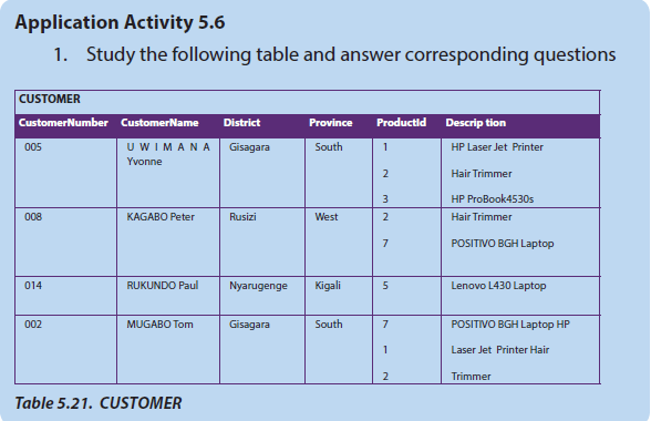
Let consider the database with table CUSTOMER identified by CustomerName,
Address, TelephoneNumber, CreditLimit, ItemOrdered,Quantity and Price.
This can easily be implemented in a relational database as follow:
However, a customer may order several items and each customer in the
database may order a different number of items. This situation makes it difficult
to implement the data in a relational database, since we do not know how many
order entries to allow.
2. Is this structure simple?
3. If this database structure is complex, identify the anomalies it has and suggest
the solution to the database designer to make it simple.
5.5.1. Introduction
Another method for designing a relational database is to use a process commonly
known as normalisation. The goal is to generate a set of relation schemas that
allows us to store information without unnecessary redundancy, yet also allows
us to retrieve information easily. The approach is to design schemas that are in an
appropriate normal form. Therefore, normalisation is a part of the
database designprocess. Normalisation is a series of steps designed to remove repeating groups
and unwanted functional dependencies. Normalisation is a design technique for
constructing a set of table designs from a list of data items. . It is also used to avoid
insertion, deletion and updating anomalies. Therefore it used to improve on existing
table designs.
5.5.2. Normal Forms
Normalization theory defines six normal forms (NF). Each normal form involves a set
of dependency properties that a schema must satisfy and each normal form gives
guarantees about the presence and/or absence of update anomalies. To correct
update anomalies in a database, you must convert tables to various types of normal
forms.
The most common normal forms are First Normal Form (1NF), Second Normal Form
(2NF), Third Normal Form(3NF) and Fourth Normal Form(4NF).
a. First Normal Form
A relation (table) that contains a repeating group (multiple entries for a single record)
is called unnormalised relation. Removing repeating groups is the starting point in
the quest to create tables that are as free of problems as possible. The conversion
to first normal form (lNF) requires splitting the data into two groups. Tables without
repeating group are said to 1NF.
A relation is in first normal form if and only if the domain of each attribute contains
only atomic (indivisible) values, and the value of each attribute contains only a single
value from that domain
Example:
A database has been designed to store data about sellers and the products they
have sold.
The following facts help to define the structure of the database:
• each seller works in a particular shop
• each seller has a unique Surname
• each shop has one or more sellers
• each product which is sold is manufactured by one company only
• each seller can sell any of the products
• the number of products that each seller has sold is recorded
This table is not in 1NF because:
1. SHOPSALES table has repeated group of attributes
(ProductName, Manufacturer)
(ProductName, NumberofProducts),
(NumberofProducts, Manufacturer)
2. each seller has a number of products
3. SurName and ShopName would need to be repeated for each record
The following table is in 1NF because it does not contain repeating groups
b. Second Normal Form (2NF)
For the second normal form, the relation must first be in 1NF. The relation is
automatically in 2NF if, and only if, the Primary Key comprises a single attribute.
To move to 2NF, a table must first be in 1NF.
The database is changed to the following design:
SELLER (SurName, ShopName)
PRODUCTSSOLD (SurName, ProductName, NumberofProducts, Manufacturer)
Table SELLER is in Second Normal Form because attribute ShopName depends on
primary key SurName; the same on PRODUCTSSOLD where NumberofProducts
and Manufacture attributes depends on composite primary key SurName,
ProductName. The link between these two tables is: primary key of SELLER table is
FirstName, links to FirstName in PRODUCTSSOLD table, FirstName in SalesProducts
table is foreign key
c. Third Normal Form (3NF)
To be in third normal form, the relation must be in second normal form. Also
all transitive dependencies must be removed; a non-key attribute may not be
functionally dependent on another non-key attribute.
In our case on table PRODUCTSSOLD, Manufacturer attribute is dependent on
ProductName, which is not the primary key of the PRODUCTSSOLD table therefore
there is no key dependency.
Process for 3NF:
1. Eliminate all dependent attributes in transitive relationship(s) from each of
the tables that have transitive relationship.
2. Create new table(s) with removed dependency.
3. Check new table(s) and modified table(s) to make sure that each table
does not contain contains inappropriate dependencies.
See the three new tables below.
SELLERS (SurName, Shop)
PRODUCTSSOLD (SurName, ProductName, NumberofProducts)
PRODUCTS (ProductName, Manufacturer)
Table: PRODUCTSSOLDM1
d. Boyce-Codd Normal Form (BCNF)
When a table has more than one candidate key, anomalies may result even though
the relation is in 3NF. Boyce-Codd normal form is a special case of 3NF. A relation
is in BCNF if, and only if, every determinant is a candidate key.
Example
Consider the following table STUDENT
The following facts help to define the structure of the database:
1. Each Student may major in several Combinations.
2. For each Combination, a given Student has only one ClassTeacher.
3. Each Combination has several Advisors.
4. Each ClassTeacher advises only one Combination.
5. Each ClassTeacher advises several Students in one Combination.
The functional dependencies for this table are:
1. StudentId, Combination→ClassTeacher
2. ClassTeacher →Combination
Anomalies for this table include:
• Delete→Student deletes ClassTeacher inforamtion
• Insert→a new ClassTeacher needs a Student
• Update →inconsistencies or contradiction
Because no single attribute which is a candidate key, primary key can be
StudentId, Combination, Student_id,ClassTeacher.
To reduce STUDENT table to BCNF, there is creation of two tables:
• STUDENTTEACHER (Studentid, ClassTeacher)
• TEACHERCOMBINATION(ClassTeacher, Combinationr)
e. Fourth Normal Form (4NF)
Fourth normal form eliminates independent many to one relationships between
columns.
A relation is in Fourth Normal Form:
• A relation must first be in Boyce-Codd Normal Form.
• Given relation may not contain more than one multivalued attribute.
The multi valued dependency X→Y holds in a relation R if whenever there is two
tuples of R that same in all the attributes of X, then we can swap their Y components
and get two new tuples that are also in R.
Primary key→{StudentId , Subject , Clubs}
• Many StudentId have same Subject.
• Many StudentId have same Clubs.
Thus violates 4NF.
To convert to 4NF, the table STUDENTCLUB is changed to the following design:
STUDENTSUBJECT {StudentId, Subject}
Is this normalised table? If not,
convert it to 1NF, 2NF and 3NF.
2. Consider the following table SUBJECT that contains multivalued
dependency thus it is in 3NF, use it to answer asked questions
i. Identify functional dependencies exist in this tabale above
ii. Eliminate those dependencies.
Question 1.
The database below is composed of two tables. Use it to answer asked questions
i. What is primary key for each table and give reasons.
ii. Identify the foreign key in the BOOKS table.
iii. Identify the candidate keys in both tables.
iv. Identify the relationship between BORROWERS and BOOKS tables
and draw the E-R model.
v. Does the BOOKS table exhibit referential integrity? Why or why not?
Question 2.
Write an ER diagram for Banking System. Assume your own entities (minimum 5),
attributes and relation. Mention the cardinality ratio.
Question 3.
A picture gallery owner has decided to set up a database to keep information
about the pictures he has for sale. The database table, PICTURE, will contain the
following fields:
PictureTitle; PictureArtist; PictureDescription; CatalogueNumber; PictureSize (in
MB); PicturePrice; ArrivedDate (date picture arrived at gallery); Status(whether
picture is already sold)
PictureTitle; PictureArtist; PictureDescription; CatalogueNumber; PictureSize (in MB);
PicturePrice; ArrivedDate (date picture arrived at gallery); Status(whether picture is
already sold)
i. State what data type you would choose for each field.
ii. State which field you would choose for the primary key.
iii. Complete the query-by-example grid below to select and show the
CatalogueNumber, PictureTitle and PicturePrice of all unsold pictures
by the artist ‘GATOTO’.
 5.1.2 The logical levelThe logical level makes it possible to create relational structures enabling us to put
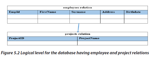 5.1.3 Physical levelThe physical level is concerned with how data will be encoded and stored. It
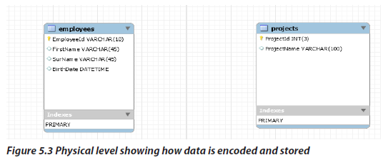 Application Activity 5.1Galleries keep information about artists, their identification, their names, birth address,
 Example: SCHOOLS Database• A View for registrar officeCourse info (coursid:string,enrollment:integer)• The conceptual schema:
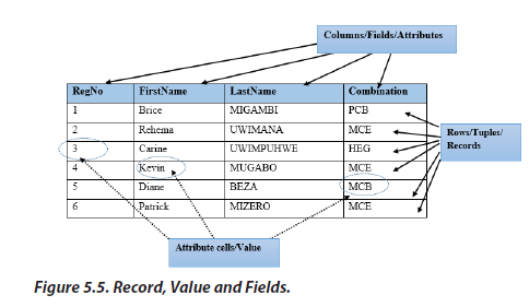 d. Null valueIn many situations every row and column will contain data, but there cases where it
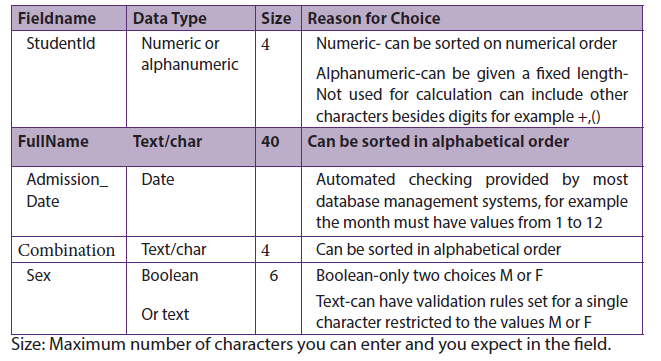 Table 5.1: Datatype exampleApplication Activity 5.3.1. Suppose that a hospital wants to develop system which manages
 a. Using correct terminology, identify and describe all the components of
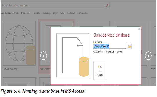 Steps for creating a table in Microsoft Access-Design View1. Open an created database in access DBMS2. Click on create tab from menu bar3. In table group click on table design icon4. Fill field names, data type and their descriptionsData in an Access table is stored in various fields. Those fields have different properties
 Steps for creating relationship between created tables1. Open a created database in access DBMS2. Click on database tools tab from menu bar3. In relationships group click on relationships icon then the relationships
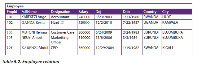 Steps for creating a query using design view-Query by exampleCreation of a query in design view has three rows, one to sort the fields, the other
 Output:
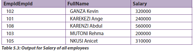 Query2: The CEO wants to see only EmpId and FullNames where Salary is less or
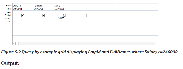
 Query 3: The following search condition was entered using a query design view
 What will be displayed?Output:
 5.3.3 Dynamic queries using parameterA parameter is a piece of information you supply to a query right as you run it.Creating a parameter queryCreating a parameter is similar to adding a normal criterion to a query:1. Create a select query, and then open the query Design view.2. In the Criteria row of the field you want to apply a parameter to, enter the
 Fill in the value you’re looking for, and then click OK.Specify parameter data typesTo specify the data type for parameters in a query:1. With the query open in Design view, on the Design tab, in the Show/Hide
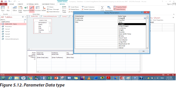 Application Activity 5.4.The database WORLD is composed of one table called WORLDCITIES Figure 5.14.
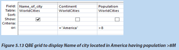 Figure 5.13 QBE grid to display Name of city located in America having population >8MShow what would be the output.2. Copy and Complete the query design view grid below to select and
 5.4. ENTITY-RELATIONSHIP MODEL5.4.1. IntroductionLearning Activity 5.5.A School needs to store information about Teacher (identified by TeacherId, FirstName,
 2. Relationships between Entities
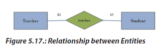 3. Entity Types• Entity types ->boxes• Weak entity type -> double box
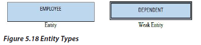 Entity types are similar to classes; they describe potential objects (entities) that will
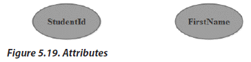 5. Link between attribute and entity setLines represent linking of attributes (properties) to entity sets.
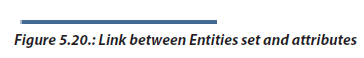 5.4.4. Entities and entity setsAn entity set is a set of entities of the same type that share the same properties. A
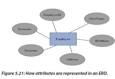 The types of attributes are:Simple (atomic) attribute – This type of attribute has a single component. It is called
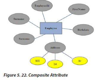 Single valued attribute – This type of attribute has one value for one entity. For
 Derived attribute – A derived attribute has its value computed from another attribute
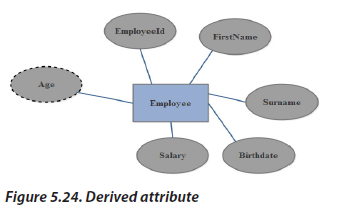 Unstable attributes - This type of attribute have values that always change. For
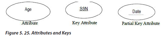 Entity Types and AttributesAll regular entity types must have a key attribute or set of key attributes, Weak entity
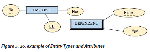 NullsA null is a special symbol, independent of data type, which means either unknown
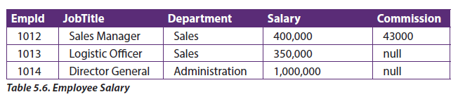 In this case commission can be left nullRelationship setsA relationship set is a set of relationships between two or more sets of entities, and
 Relationships indicate a meaningful connection between two entity types,
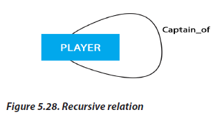 Roles and Recursive RelationsWhen an entity set appears in more than one relationship, it is useful to add labels to
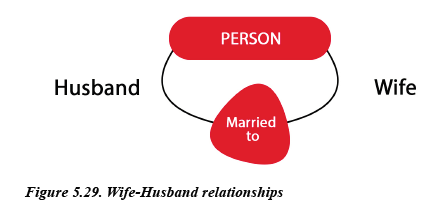 5.4.7.2 Binary RelationshipIn a binary relationship, two entities are involved. Consider the example where each
 5.4.7.3. Ternary Relationship
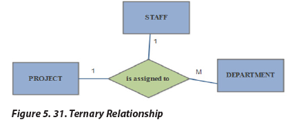 In a ternary relationship, three entities are simultaneously involved. Ternary
 The degree of relationship, which determines how many instances of an entity relate
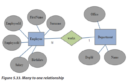 5.4.8.4. Many-to-many (M: M):Multiple instances of an entity can relate to multiple instances of another entity.For our company database. The relationship between employee and department
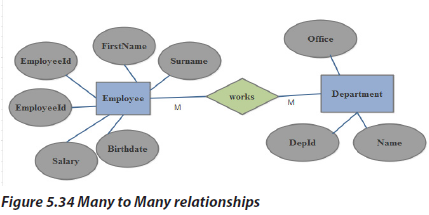 Participation and CardinalityParticipation and cardinality define constraints on relationships; Participation
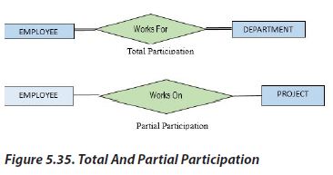 Participation ConstraintArrowheads can be used to indicate an upper bound of 1 for participation
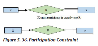 Cardinality Ratios: a cardinality ratios specify the maximum number of relationship
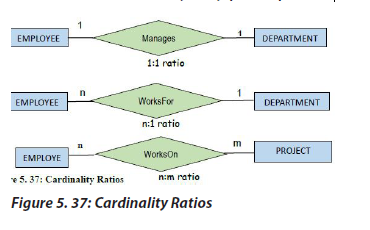 Structural ConstraintsStructural constraints specify the minimum and maximum number of relationshipinstances that an entity may participate in.
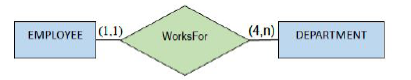 An employee must work for exactly 1 department. A department must have at least
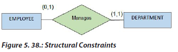 Participation and CardinalityThere’s generally numerous ways to express a relationship constraint.
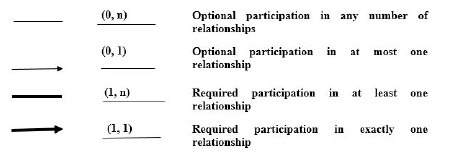 Equivalent NotationsAn employee can manage at most one department.
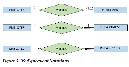 Equivalent Notations• An employee must work for exactly one department.• A department must have at least one employee.
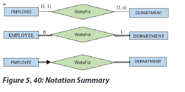
 Application Activity 5.5Given an ER diagrams belowWrite the degree, cardinality, participation and Constraints of each relationship in
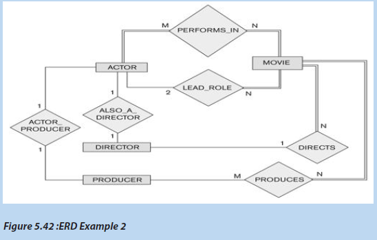
 Relationships representation1. Consider a database used to record information about the marks that
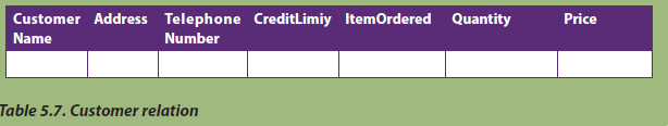 However, a customer may order several items and each customer in the
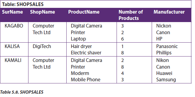 This table is not in 1NF because:1. SHOPSALES table has repeated group of attributes(ProductName, Manufacturer)(ProductName, NumberofProducts),(NumberofProducts, Manufacturer)2. each seller has a number of products3. SurName and ShopName would need to be repeated for each recordThe following table is in 1NF because it does not contain repeating groups
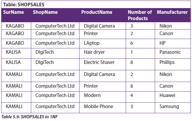 b. Second Normal Form (2NF)For the second normal form, the relation must first be in 1NF. The relation is
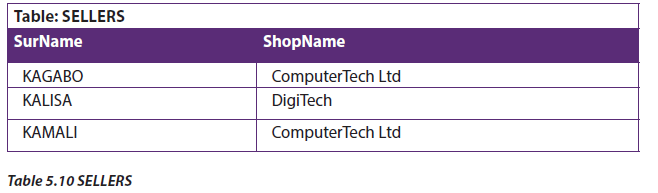
 Table SELLER is in Second Normal Form because attribute ShopName depends on
 Table: PRODUCTSSOLDM1
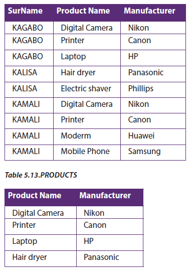
 d. Boyce-Codd Normal Form (BCNF)When a table has more than one candidate key, anomalies may result even though
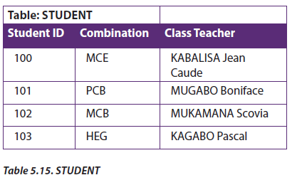 The following facts help to define the structure of the database:1. Each Student may major in several Combinations.2. For each Combination, a given Student has only one ClassTeacher.3. Each Combination has several Advisors.4. Each ClassTeacher advises only one Combination.5. Each ClassTeacher advises several Students in one Combination.The functional dependencies for this table are:1. StudentId, Combination→ClassTeacher2. ClassTeacher →CombinationAnomalies for this table include:• Delete→Student deletes ClassTeacher inforamtion• Insert→a new ClassTeacher needs a Student• Update →inconsistencies or contradictionBecause no single attribute which is a candidate key, primary key can beStudentId, Combination, Student_id,ClassTeacher.To reduce STUDENT table to BCNF, there is creation of two tables:• STUDENTTEACHER (Studentid, ClassTeacher)• TEACHERCOMBINATION(ClassTeacher, Combinationr)
 e. Fourth Normal Form (4NF)Fourth normal form eliminates independent many to one relationships between
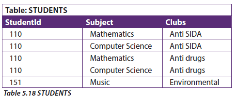 Primary key→{StudentId , Subject , Clubs}• Many StudentId have same Subject.• Many StudentId have same Clubs.Thus violates 4NF.
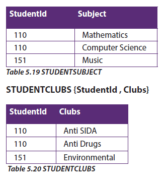
 Is this normalised table? If not,
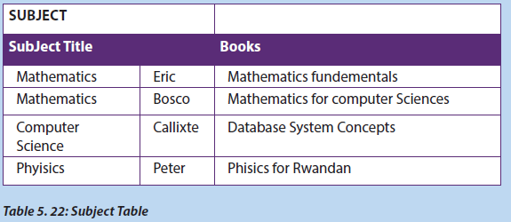 i. Identify functional dependencies exist in this tabale aboveii. Eliminate those dependencies.END UNIT ASSESSMENTQuestion 1.The database below is composed of two tables. Use it to answer asked questions
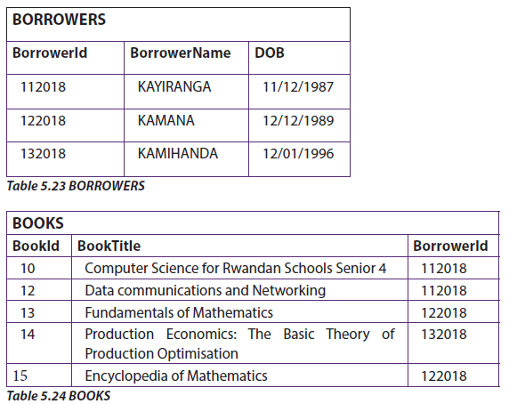 i. What is primary key for each table and give reasons.ii. Identify the foreign key in the BOOKS table.iii. Identify the candidate keys in both tables.iv. Identify the relationship between BORROWERS and BOOKS tables
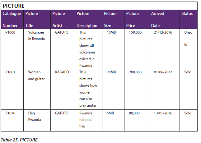 PictureTitle; PictureArtist; PictureDescription; CatalogueNumber; PictureSize (in MB);