UNIT 10: ANALOG AND DIGITAL SIGNALS
Key unit competence: Differentiate analog from digital signals.
Unit Objectives:
By the end of this unit I will be able to;
◊ Explain the transmission of information in a communication
system.
◊ Explain with examples the use of digital and analog signals ineveryday applications.
Introductory Activity
a. There has been a move by the government of Rwanda to make
her citizens to change from using analog devices to digital
devices. Analog devices transmit and receive signals in analog
form whereas digital devices transmit and receive signals
digitally.
b. a) What are different forms of signals you know that you
normally use in daily life communication?
c. b) Why do you think there is a need to change from analog to
digital signal transmission?
d. c) Mutesi communicates to her brother Ndayisenga who
studies abroad using Facebook. Is the flow of information
analog or digital? Explain your argument.
e. d) Using information gained in above questions, discuss
different signals you know.
10.1 INTRODUCTION
A signal is any kind of physical quantity that conveys information. Audible
speech is certainly a kind of signal, as it conveys the thoughts (information)
of one person to another through the physical medium of sound. Hand
gestures are signals too. This text is another kind of signal, interpreted by
your English-trained mind as information about electric circuits. In this
unit, the word signal will be used primarily in reference to an electrical
quantity of voltage or current that is used to represent or signify some other
physical quantity.
A communication system is made up of devices that employ one of two
communication methods (wireless or wired), different types of equipment
(portable radios, mobile radios, base/fixed station radios and repeaters)
accessories (examples include speaker microphones, battery eliminators and
carrying cases) and/or enhancements (encryption, digital communications,
security measures, and networking) to meet the user needs.
The most common processing of a signal in a communication system
consists of passing the signal through a linear time-invariant system. In
this context, such a system is often spoken of as a “filter”. These systems
are usually applied to reduce some undesirable components in the signal, to
compensate for some undesirable distortion of the signal, or to accentuate
some characteristic of a signal. This unit discusses digital and analog
signals and their use in modern communication.
10.2 INFORMATION TRANSMISSION
IN A COMMUNICATION SYSTEM
A communication system comprises of three sections or parts; transmitting
end, propagation medium and receiving end. This is shown on Fig. 10.1below.
The signals from information source are added to the carrier in the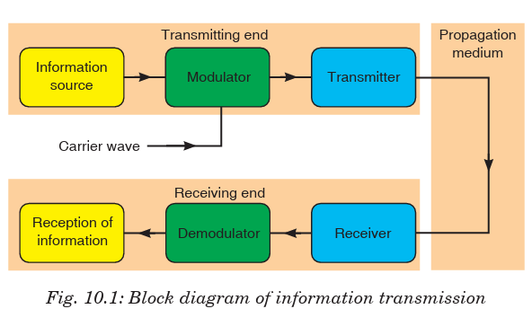
modulator. The modulated signal is sent along a channel in the propagating
medium by a transmitter. The propagation medium is a channel through
which information is transmitted. This may be a cable or free space.
At the receiving end, the receiver may have to select and perhaps amplify the
modulated signal before the demodulator extracts from it the information
signal for delivery to the receptor of information.
A propagation or transmission medium can be classified as;
Linear medium: if different waves at any particular point in medium can
be superposed.
Bounded medium: if it is finite in extent, otherwise unbound.
Uniform medium or homogeneous medium: if its physical properties
are unchanged at different points.
Isotropic medium: if its physical properties are the same in differentdirections.
10.3 COMMUNICATION TERMS AND CONCEPTS
1. Communication is the process of sharing the messages through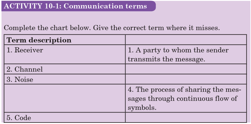
continuous flow of symbols.
2. Communicators (Sender/receiver) are the participants in communi
cation. Typically the roles reverse regularly.
3. Message is a single uninterrupted verbal or nonverbal utterance.
4. Code means a system suitable for creating/carrying messages through
a specific medium.
• encode (put into code) and
• decode (take out of code)
5. Channels (verbal, nonverbal, etc.) means the specific mechanism
(“pipeline”) used to transmit the message.
6. Mode of communication (face-to-face, television, web, phone, etc.) -
form or technology of transmission — determines kind of code used.
7. Noise - interference with message — external (physical), internal
(mental) or semantic (misunderstanding/reaction).
8. Environment (part of context) - is that which surrounds and provides
a basis for the meaning of a message:
• Physical (surroundings)
• Temporal (point in time)
• Relational (the existing relationship between communicators -
friends, strangers, etc.)
• Cultural
(language and behaviour of community and the
communicator(s) come from)
9. Feedback - checks effects of messages
• positive feedback eg. “keep doing what you’re doing”
• negative feedback eg. “change what you’re doing”.
10. Levels (contexts) of Communication
• Intrapersonal
• Interpersonal
• Public Communication
• Mass Communication (non-interactive)
• Computer Mediated Communication (interactive)
10.4 ELEMENTS OF COMMUNICATION
ACTIVITY 10-2: Elements of Communication
Aim: To find out the elementes of communication in a basic
communication model.
Carefully analyse Fig. 10.2 below and describe the elements of communication
available.
Communication is a two-way process that results in a shared meaning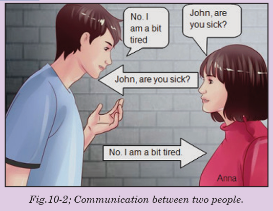
or common understanding between the sender and the receiver. An
understanding of how communication works can help us to understand and
improve our communication. The basic communication model consists of
five elements of communication: the sender, receiver, message, channel and
feedback.
Sender
The sender is a party that plays the specific role of initiating communication.
To communicate effectively, the sender must use effective verbal as well as
nonverbal techniques. Such as:-
• Speaking or writing clearly.
• Organizing your points to make them easy to follow and understand.
• Maintaining eye contact.
• Using proper grammar.
• Giving accurate information.
All the above components are essential in the effectiveness of your message.
One will lose the audience if it becomes aware of obvious oversights on ones
part. The sender should have some understanding of who the receiver is, in
order to modify the message to make it more relevant.
Receiver
The receiver means the party to whom the sender transmits the message.
A receiver can be one person or an entire audience of people. In the basic
communication model, the receiver is directly connected with the speaker.
The receiver can also communicate verbally and nonverbally. The best way
to receive a message is:
• To listen carefully.
• Sitting up straight.
• Making eye contact.
• Don’t get distracted or try to do something else while you’re listening.
• Nodding and smiling as you listen.
• Demonstrate that you understand the message.
Message
The message is the most crucial element of effective communication which
includes the content a sender conveys to the receiver. A message can come
in many different forms, such as an oral presentation, a written document,
an advertisement or just a comment. In the basic communication model, the
way from one point to another represents the sender’s message travelling to
the receiver. The message isn’t necessarily what the receiver perceive it to
be. Rather, the message is what the sender intends the message to be. The
sender must not only compose the message carefully, but also evaluate the
ways in which the message can be interpreted.
Channel
The channel is a medium through which a message travels from the sender
to the receiver. The message travels from one point to another via a channel
of communication. The channel is a physical medium stands between the
sender and receiver.
Many channels or types of communication exist, such as
• The spoken word,
• Radio or television,
• An Internet site or
• Something written, like a book, letter or magazine.
Every channel of communication has its advantages and disadvantages. For
example, one disadvantage of the written word, on a computer screen or in
a book, is that the receiver cannot evaluate the tone of the message. For this
reason, effective communicators should make written word communications
clear so receivers don’t rely on a specific tone of voice to convey the message
accurately. The advantages of television as a channel for communication
include its expansive reach to a wide audience and the sender’s ability to
further manipulate the message using editing and special effects.
Feedback
This describes the receiver’s response or reaction to the sender’s message.
The receiver can transmit feedback through asking questions, making
comments or just supporting the message that was delivered. Feedback
helps the sender to determine how the receiver interpreted the messageand how it can be improved.
10.5 TYPES OF INFORMATION AND REQUIREMENTS
Constructional/creative information: This includes all information
that is used for the purpose of producing something. Before anything can
be made, the originator mobilizes his intelligence, his supply of ideas, his
know-how, and his inventiveness to encode his concept in a suitable way.
Operational information: All concepts having the purpose of maintaining
some “industry” in the widest sense of the word are included under this kind
of information. Many systems require operational information in the form
of programs for proper functioning. Examples of operational information
include:
• the operating system of a computer (eg. DOS programs),
• the program controlling a robot or a process computer,
• warning systems for airplanes and ships,
• the hormonal system of the body
Communication information: This is composed of all other kinds of
information, eg. letters, books, phone calls, radio transmissions, bird songs
and also the message of the Bible. Aspect of such information does not
include the construction of a product, neither it is involved in maintaining
some process. The goals are transmission of a message, spreading joy,amusement, instruction and personal confidences.
10.6 SIMPLEX TRANSMISSION
Simplex transmission is a single one-way base band transmission. Simplex
transmission, as the name implies, is simple. It is also called unidirectional
transmission because the signal travels in only one direction. An example
of simplex transmission is the signal sent from the TV station to the home
television.
Data in a simplex channel is always one way. Simplex channels are not
often used because it is not possible to send back error or control signals tothe transmit end.
10.7 HALF-DUPLEX COMMUNICATIONS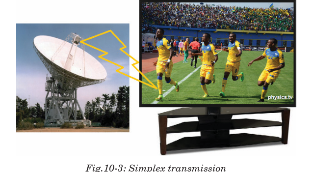
Half-duplex transmission is an improvement over simplex transmission
because the traffic can travel in both directions. Unfortunately, the road is
not wide enough to accommodate bidirectional signals simultaneously. This
means that only one side can transmit at a time. Two-way radios, such as
police or emergency communications mobile radios, work with half-duplex
transmissions. If people at both ends try to talk at the same time, none ofthe transmissions get through.
10.8 FULL-DUPLEX COMMUNICATIONS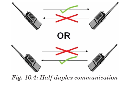
Full-duplex transmission operates like a two-way, two-lane street. Traffic
can travel in both directions at the same time.
A land-based telephone conversation is an example of full-duplex
communication. Both parties can talk at the same time, and the person
talking on the other end can still be heard by the other party while they are
talking. Although when both parties are talking at the same time, it might
be difficult to understand what is being said.
Full-duplex networking technology increases performance because data
can be sent and received at the same time. Digital subscriber line (DSL),
two-way cable modem, and other broadband technologies operate in
full-duplex mode. With DSL, for example, users can download data to theircomputer at the same time they are sending a voice message over the line.
10.9 BANDWIDTH AND SIGNAL FREQUENCY
Frequency is a parameter that determines how often the sinusoidal signal
goes through a cycle. It is usually represented with the symbol f, and it hasthe unit hertz.
Where T is a periodic time and is measured in seconds.
The bandwidth of a composite signal is the difference between the highest
and the lowest frequencies contained in that signal. It is typically measured
in hertz, and may sometimes refer to passband bandwidth or basebandbandwidth, depending on context.
10.10 ANALOG SIGNAL SYSTEM
A system is a physical set of components that take a signal and produces a
signal. In terms of engineering, the input is generally some electrical signal
and the output is another electrical signal.
Analog systems operate with values that vary continuously and have no
abrupt transitions between levels. For a long time, almost all electronic
systems were analog, as most things we measure in nature are analog. For
example, your voice is analogous; it contains an infinite number of levels
and frequencies. Therefore, if you wanted a circuit to amplify your voice, an
analog circuit seems a likely choice.
In Rwanda recently analog systems were replaced by digital systems that
provide greater capacity of data transfer and increased reliability and
security.
Example of an analog electronic system
A public address system
A public address system (PA system) is an electronic sound amplification
and distribution system with a microphone, amplifier and loudspeakers, used
to allow a person to address a large public, for example for announcementsof movements at large and noisy air and rail terminals or a sports stadium.
10.11 ANALOG SIGNALS
Analog signal is a continuous signal that contains time varying quantities.
An analog signal is a continuous wave denoted by a sine wave and may
vary in signal strength (amplitude) or frequency (time). The sine wave’s
amplitude value can be seen as the higher and lower points of the wave,
while the frequency (time) value is measured in the sine wave’s physicallength from left to right.
Analog signal can be used to measure changes in physical phenomenon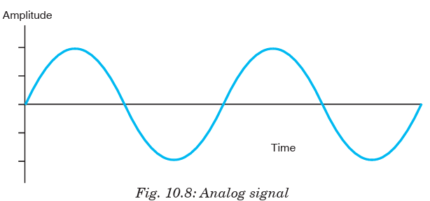
such as light, sound, pressure, or temperature. For instance, microphone
can convert sound waves into analog signal. Even in digital devices, there
is typically some analog component that is used to take in information from
the external world which will then get translated into digital form –using
analog to digital converter.
10.12 ADVANTAGES AND DISADVANTAGES OF
ANALOG SIGNALS
Advantages
• Uses less bandwidth than digital sounds.
• More accurate representation of sound.
• It is the natural form of sound.
• Because of editing limitations, there is little someone can do to tinker
with the sound, so what you are hearing is the original sound.
Disadvantages
• There are limitations in editing.
• Recording analog sound on tape is expensive.
• It is harder to synchronize analogous sound.
• Quality is easily lost if the tape becomes ruined.
• A tape must always be wound and rewound in order to listen to specific
part of sound which can damage it.
• Analog is susceptible to clipping where the highest and lowest notes of
a sound are cut out during recording.
10.13 DIGITAL SIGNALS
In electronic signal and information processing and transmission, digital
technology is increasingly being used because, in various applications, digital
signal transmission has many advantages over analog signal transmission.
Numerous and very successful applications of digital technology include the
continuously growing number of PC’s, the communication network ISDN as
well as the increasing use of digital control stations (Direct Digital Control:
DDC).
Unlike analog technology which uses continuous signals, digital technology
encodes the information into discrete signal states. When only two states
are assigned per digital signal, these signals are termed binary signals.One single binary digit is termed a bit - a contraction for binary digit.
10.14. ADVANTAGES OF DIGITAL TECHNOLOGY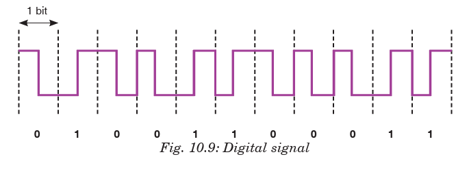
•More capacity from the same number of frequencies; that is, they
provide superior Spectral Efficiency. This is a result of the modulation
methods used, and the fact that, in many cases more than one
‘conversation’ can be accommodated within a single radio channel.
• Consistent voice clarity at low received signal levels near the
edge of coverage. The general consensus is that digital radios provide
better audio quality than analog ones. With analog FM radios, the audio
quality steadily declines as the received signal strength gets weaker.
Digital radios however, will have a consistent audio quality throughout
the full service area. The edges of the coverage area in a digital radio
system are similar to those experienced with cellular telephones.
• Data is defined in the standard. This means data implementations
are no longer proprietary, there are a wide variety of data mechanisms
and inter operability can extend into the data domain. With the accepted
increase of efficiency by using data communications over voice, this
will further increase the usability and effectiveness of digital radio
systems.
• Secure transmissions: In digital technologies, data and voice can
be secured using encryption without impacting voice quality usingindustry standard encryption techniques.
10.15 COMPARING DIGITAL AND ANALOG SIGNALS
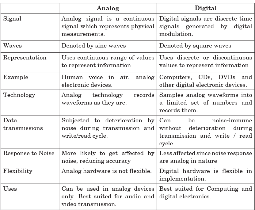

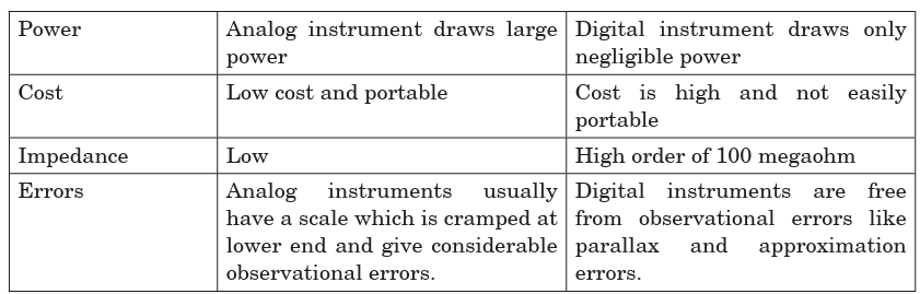
Principle of digital signal systems
A digital signal refers to an electrical signal that is converted into a pattern
of bits. Unlike an analog signal, which is a continuous signal that contains
time-varying quantities, a digital signal has a discrete value at each sampling
point. The precision of the signal is determined by how many samples are
recorded per unit of time. For example, the illustration of fig below shows
an analog pattern (represented as the curve) alongside a digital pattern(represented as the discrete lines).
Analog pattern alongside digital pattern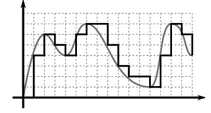
A digital signal is easily represented by a computer because each sample
can be defined with a series of bits that are either in the state 1 (on) or 0 (off).
Digital signals can be compressed and can include additional information
for error correction. A signal in which the original information is converted
into a string of bits before being transmitted. A radio signal, for example,
will be either on or off. Digital signals can be sent for long distances and
suffer less interference than analog signals.
Boolean functions may be practically implemented by using electronic
gates. The following points are important to understand.
• Electronic gates require a power supply.
• Gate INPUTS are driven by voltages having two nominal values, e.g. 0 V
and 5 V representing logic 0 and logic 1 respectively.
• The OUTPUT of a gate provides two nominal values of voltage only, e.g. 0
V and 5 V representing logic 0 and logic 1 respectively. In general, there
is only one output to a logic gate except in some special cases.
• There is always a time delay between an input being applied and theoutput responding.
Application Activity
Question on digital and analogue signal.
1. The two basic types of signals are analog and:
A. Digilog
B. Digital
C. Vetilog
D. Sine wave
2. Which of the following characterizes an analog quantity?
A. Discrete levels represent changes in a quantity.
B. Its values follow a logarithmic response curve.
C. It can be described with a finite number of steps.
D. It has a continuous set of values over a given range.
3. Which type of signal is represented by discrete values?
A. Noisy signal
B. Nonlinear
C. Analog
D. Digital
4. A data conversion system may be used to interface a digital computer system to:
A. An analog output device
B. A digital output device
C. An analog input deviceD. A digital printer
10.16 LOGIC GATES
There are three basic logic gates each of which performs a basic logic
function. They are called NOT, AND and OR. All other logic functions can
ultimately be derived from combinations of these three. For each of the
three basic logic gates a summary is given including the logic symbol, thecorresponding truth table and the Boolean expression.
The AND gate is an electronic circuit that gives a high output (1) only if all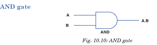
its inputs are high. A dot (.) is used to show the AND operation i.e. A.B. Itcan also be written as AB.
The OR gate is an electronic circuit that gives a high output (1) if one or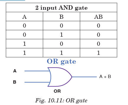
more of its inputs are high. A plus (+) is used to show the OR operation.

The NOT gate is an electronic circuit that produces an inverted version of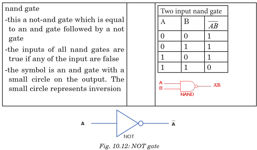
the input at its output. It is also known as an inverter. If the input variable
is A, the inverted output is known as NOT A. This is also shown as A′, or A.as shown at the outputs.

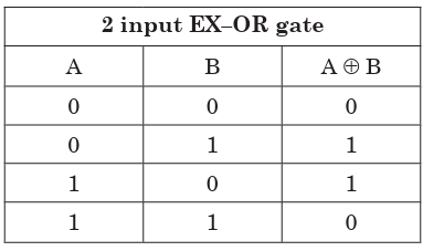
Another useful gate used in the digital logic circuits is EX–OR gate.
The ‘Exclusive-OR’ gate is a circuit which will give a high output if either,
but not both, of its two inputs are high. An encircled plus sign (⊕) is usedto show the EX–OR operation.
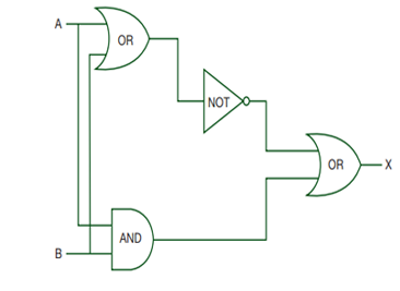
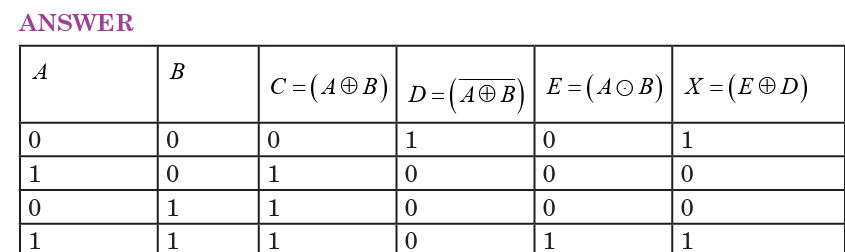
EXAMPLE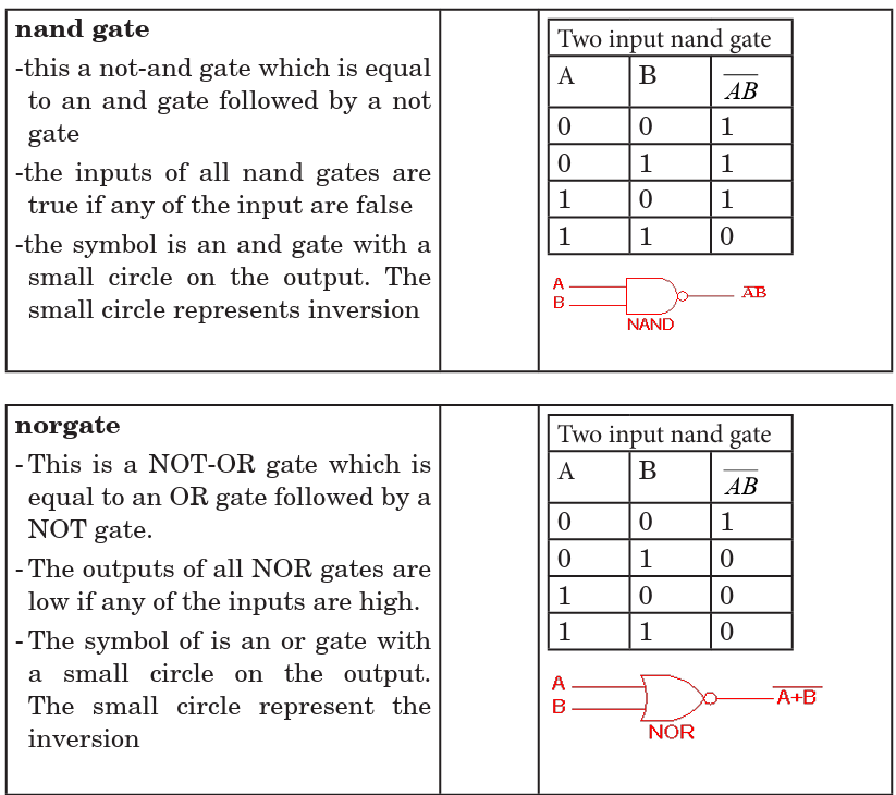
Construct a truth table of the following logic circuit
Application Activity
1. Produce a truth table from the following logic circuit (network)
2. For the logic circuits below produce the truth tables. Rember, if there are 2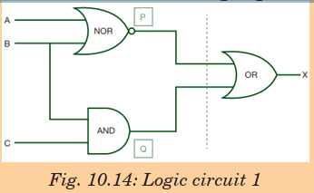
inputs then there will be 4 outputs; if there are 3 inputs then there will be 8
possible outputs. Use the ida shown in the logic circuits discussed in section10.6.
END OF UNIT ASSESSMENT
1. There has been a move to advise people to change from using analog
systems to start using digital systems especially here in Rwanda. Do
you support this move? If yes, why? If no why not?2. Produce a truth table from the following logic circuit (network).
3. For the logic circuits below produce the truth tables. Remember, if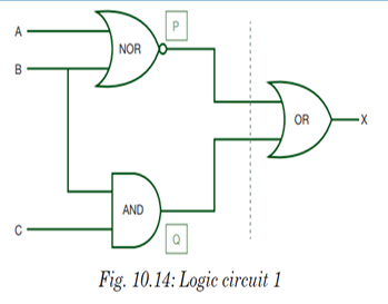
there are 2 inputs then there will be 4 outputs; if there are 3 inputs
then there will be 8 possible outputs. Use the idea shown in the logiccircuits discussed in section 10.6.
UNIT SUMMARY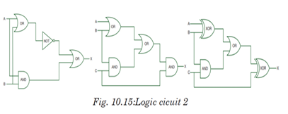
Information transmission in a communication system
The signals from information source are added to the carrier in the
modulator. The modulated signal is sent along a channel in the propagating
medium by a transmitter. The propagation medium is a channel through
which information is transmitted. This may be a cable or a free space.
Communication Terms and Concepts
•Communication
• Communicator
• Message
• Medium
• Noise
• Environment
• Feedback
• Levels
Elements of communication
• Sender
• Receiver
• Message
• Channel
• Feedback
Types of information and requirements
•Constructional/creative information
• Operational information
• Communicational information
Simplex transmission
Simplex transmission is a single one-way base band transmission. Simplex
channels are not often used because it is not possible to send back error or
control signals to the transmit end.
Half-duplex communications
Half-duplex transmission is an improvement over simplex because the
traffic can travel in both directions. Full-duplex networking technology
increases performance because data can be sent and received at the same
time.
Bandwidth and signal Frequency
The bandwidth of a composite signal is the difference between the highest
and the lowest frequencies contained in that signal.Mathematically, the bandwidth is given by;
• Medium
• Noise
• Environment
• Feedback
• Levels
Elements of communication
Analogue signal system
Analogue systems operate with values that vary continuously and have no
abrupt transitions between levels.
Analog signals
Analog signal is a continuous signal that contains time varying quantities.
An analog signal is a continuous wave denoted by a sine wave and may vary
in signal strength (amplitude) or frequency (time).
Digital signals
Unlike analog technology which uses continuous signals, digital technology
encodes the information into discrete signal states. Numerous and very
successful applications of digital technology include the continuously
growing number of PC’s, the communication net work ISDN as well as the
increasing use of digital control stations (Direct Digital Control: DDC).
Advantages of digital technology
• More capacity from the same number of frequencies.
• Consistent voice clarity at low received signal levels near the edge of
coverage.
• Data is defined in the standard.
• Secure transmissions.
Logic gates
There are three basic logic gates each of which performs a basic logic
function, they are called NOT, AND and OR. All other logic functions canultimately be derived from combinations of these three.