Topic outline
UNIT 1:WAVE AND PARTICLE NATURE OF LIGHT
Key unit competence: Analyze the nature of light.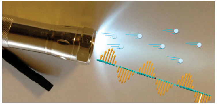
Unit Objectives:
By the end of this unit I will be able to;
◊ Explain the Planck’s quantum theory and apply it to other theories.
◊ Explain photoelectric effect and use it to derive and apply
Einstein’s photoelectric equation
◊ explain photoelectric effect and use it to derive and apply
Einstein’s photoelectric equation.
◊ Explain the wave theory of light and state its limitations.
◊ Evaluate properties of light as a wave.
◊ Differentiate electron microscope and Compton Effect as applied inmedecine.
1.0 INTRODUCTION
Until the late 19th century physicists used to explain the phenomena
in the physical world around them using theories such as mechanics,
electromagnetism, thermodynamics and statistical physics that are known
as classical theories.
At the turn of the 19th century, more and more experiments showed effects
that could not be explained by these classical theories. This indicated a need
for a new theory that we now know as quantum mechanics. Quantum
mechanics is the system of laws which governs the behaviour of matter on
the atomic scale. It is the most successful theory in the history of science,
having withstood thousands of experimental tests without a single verifiable
exception. So, the quantum mechanics is required to analyze the behaviour
of photons, electrons and other particles that make up the universe.
This theory is the most useful in various studies especially for Radiography
and Physiotherapy in Medicine, electrons and photons in Chemistry and
Astronomy in Geography.
Introductory Activity
Clearly observe the image shown on Fig.1-1, with kids playing on a
slide with the help of their father Mr. John and answer the questionsthat follow.
a) Sarah is climbing the ladder. How do you think her potential energy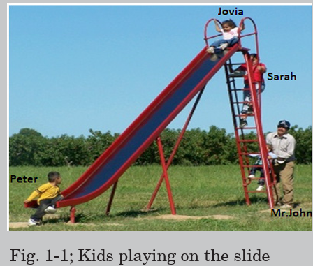
is changing?
b) Comment on the potential energies of Jovia and Peter.c) How is the change in the potential energy of Jovia as she slides down?
What do you think is Mr. John doing on the young kid? Give your comments.
Fig.1.2 below shows how light interacts with an electron. F and B arethe terminals of the circuit (the wires of an external circuit).
The working mechanism of Fig.1.2 is used in solar cells and solar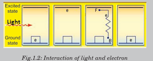
panels. Clearly analyse Fig.1.2 and compare it with the situation on
Fig.1.1, take children as electrons at different points or positions, andmake your comments.
1.1 NATURE AND PROPERTIES OF LIGHT
1.1.1 Particle theory of light
The nature and properties of light has been a subject of great interest and
speculation since ancient times. Until the time of Isaac Newton (1642
1727), the Greeks believed that light consisted of tiny particles (corpuscles)
that either were emitted by a light source or emanated from the eyes of the
viewer.
Newton the chief architect of the particle theory of light held that light
consisted of tiny particles that were emitted from a light source and that
these particles stimulated the sense of sight upon entering the eye. Using
this idea (particle theory), he was able to explain reflection and refraction
(bending) of light.
However , his derivation of the law of refraction depend on the assumption
that light travels faster in water and in glass than in air, an assumption
later shown to be false.Most scientists accepted Newton’s particle theory.
1.1.2 Wave theory and Planck’s quantum theory of light.
Does light exhibit diffraction? In the mid-seventeenth century, the Jesuit
priest Francesco Grimaldi (1618–1663) had observed that when sunlight
entered a darkened room through a tiny hole in a screen, the spot on the
opposite wall was larger than would be expected from geometric rays. He
also observed that the border of the image was not clear but was surrounded
by colored fringes. Grimaldi attributed this to the diffraction of light.
In 1678, one of Newton’s contemporaries, the Dutch physicist and astronomer Christian
Huygens (1629–1695), was able to explain many otherproperties of light by proposing that light is a wave.
According to the Huygens’ wave theory:
- Light travels in the form of longitudinal waves which travel with uni
form velocity in homogeneous medium.
- Different colours are due to the different wavelengths of light waves.
- We get the sensation of light when these waves enter our eyes.
- In order to explain the propagation of waves of light through vacuum,
Huygens suggested the existence of a hypothetical medium called alu
miniferous ether, which is present in vacuum as well as in all material objects. Since ether couldn’t be detected, it was attributed properties like:
- It is continuous and is made up of elastic particles.
- It has zero density.
- It is perfectly transparent.
- It is present everywhere
refraction of light by assuming that light travels more slowly in water and
in glass than in air.
Huygens’ Principle is particularly useful for analyzing what happens when
waves run into an obstacle. The bending of waves behind obstacles into
the “shadow region” is known as diffraction. Since diffraction occurs for
waves, but not for particles, it can serve as one means for distinguishingthe nature of light.
The Huygens’ Principle of the wave theory of light states that: “Every point
on a wavefront may be considered a source of secondary spherical wavelets
which spread out in the forward direction at the speed of light. The newwavefront is the tangential surface to all of these secondary wavelets.”
In 1801, the Englishman Thomas Young (1773–1829) provided the first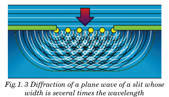
clear demonstration of the wave nature of light and showed that light beams
can interfere with one another, giving strong support to the wave theory.
Young showed that, under appropriate conditions, light rays interfere with
each other. Such behavior could not be explained at that time by a particle
theory because there was no conceivable way in which two or more particles
could come together and cancel one another.
The general acceptance of wave theory was due to the French physicist
Augustin Fresnell (1788-1827), who performed extensive experiments on
interference and diffraction and put the wave theory on a mathematical
basis. In 1850, Jean Foucault measured the speed of light in water and
showed that it is less than in air, thus ruling out Newton’s particle theory.
However, in 1900, German Physicist Max Planck (1858–1947) returned
to the particle theory of light to explain the thermal radiation emitted by
hot objects. To explain these radiations, Max Planck put forward a theory
known as Planck’s quantum theory suggests that:
1. The matter is composed of a large number of oscillating particles. These
oscillators have different frequencies.
2. The radiant energy which is emitted or absorbed by the blackbody is not
continuous but discontinuous in the form of small discrete packets of
energy and each such packet of energy is called a ‘quantum’. In case of
light, the quantum of energy is called a ‘photon’.
3. The energy of each quantum is directly proportional to the frequency (f)of the radiation, i.e.
whereas c is the speed of light, l is the wavelength and h is the Planck’s
constant (h = 6.63 × 10⁻³⁴ J.s.).
4. The oscillator emits energy, when it moves from one quantized state to
the other quantized state. The oscillator does not emit energy as long as
it remains in one energy state. The total amount of energy emitted orabsorbed by a body will be some whole number quanta. Hence,

where n is an integer.
According to the Planck’s theory, the exchange of energy between quantized
states is not continuous but discrete. This quantized energy is in small
packets of bundles. The bundle of energy or the packet of energy is called
quantum (plural quanta).
1.1.3 Wave particle duality of light
Today, scientists view light as having a dual nature—that is, light exhibits
characteristics of a wave in some situations and characteristics of a particle
in other situations.
Although the wave model and the classical theory of electromagnetism
were able to explain most known properties of light, they could not explain
some subsequent experiments. The most striking of these is the photoelec
tric effect, also discovered by Hertz: When light strikes a metal surface,
electrons are sometimes ejected from the surface. As one example of the
difficulties that arose, experiments showed that the kinetic energy of an
ejected electron is independent of the light intensity. This finding contra
dicted the wave theory, which held that a more intense beam of light shouldadd more energy to the electron.
In view of these developments, light must be regarded as having a dual nature:
Wave-particle duality postulates that all particles exhibit both wave
properties and particle properties.
• Phenomena of light like interference, diffraction and polarization can
be explained by wave theory and not by particle nature of light.
• Energy distribution in perfect blackbody radiation, photo electric effect
and Compton Effect can be explained by particle nature of light and
not by wave theory. The concept of quantum mechanics is applied even
to the motion of electrons in an atom in Bohr’s atomic model.
If light waves can behave like particles, can the particles of matter behave
like waves? As we will discover, the answer is a resounding yes. Electrons
can be made to interfere and diffract just like other kinds of waves. Light
is light, to be sure. However, the question “Is light a wave or a particle?” is
inappropriate. Sometimes light acts like a wave, and at other times it acts like a particle.
1.1.4 The principle of complementarities
The principle of complementarities refers to the effects such as wave particle
duality in which different measurements made on the system reveal it to have
either particle-like or wave-like properties. Both properties are necessary to
gain the complete knowledge of the phenomena; they are complementary to
each other; but at the same time, they also exclude each other.
Within the scope of classical physics, all characteristic properties of a given
object can be ascertained by a single experimental arrangement, although
in practice various arrangements are often convenient for the study of
different aspects of the phenomena. In fact, data obtained in such a way
simply supplement each other and can be combined into a consistent picture
of the behaviour of the object under investigation. In quantum physics,
however, evidence about atomic objects obtained by different experimental
arrangements exhibits a novel kind of complementary relationship.
EXAMPLE 1.1
The laser in a compact disc player. It uses light with a wavelength of
7.8 × 10² nm. Calculate the energy of a single photon of this light.
Solution:From Equation 1.2,
EXAMPLE 1.2
What is the ratio between the energies of two radiations, one with awavelength of 200 nm and the other with 600 nm?
The energy is inversely proportional to the wavelength.
Application Activity 1.1
1. Which of the following can be thought of as either a wave or a
particle?
a. A.Light.
b. B.An electron.
c. C.A proton.
d. D.All of the above.
2. Electrons and photons of light are similar in that
a. Both have momentum given by
b. Both exhibit wave–particle duality.
c. Both are used in diffraction experiments to explore structure.
d. All of the above
e. None of the above
3. What is quantum mechanics?
4. What is Planck’s quantum theory?
5. Explain Planck’s hypothesis or what are the postulates of Planck’s
quantum theory?
6. A laser emits light energy in short pulses with frequency 4.69 ×
1014 Hz and deposits 1.3 × 10⁻² J for each pulse. How many quanta
of energy does each pulse deposit?
7. A laser pointer with a power output of 5.00 mW emits red light
a. What is the magnitude of the momentum of each photon?
b. How many photons does the laser pointer emit each second?
8. a. Light of a certain orange colour has a wavelength of 589 nm.
What is the energy of one photon of this light? Speed of light
b. Show that the photons in a 1240 nm infrared light beam haveenergies of 1.00 eV.
1.2 PHOTON THEORY OF LIGHT AND
PHOTOELECTRIC EFFECT
Before Einstein, photoelectric effect had been observed by scientists, but
they were confused by the behavior because they didn’t fully understand
the nature of light. In the late 1800s, physicists James Clerk Maxwell in
Scotland and Hendrik Lorentz in the Netherlands determined that light
appear to behave as a wave. This was proven by seeing how light waves
demonstrate interference, diffraction and scattering, which are common to
all sorts of waves (including waves in water.)
So Einstein’s argument in 1905 that light can also behave as a set of
particles was revolutionary because it did not fit with the classical theory of
electromagnetic radiation. Other scientists had postulated the theory before
him, but Einstein was the first to fully elaborate on why the phenomenon
occurred – and the implications’. Einstein was awarded the Nobel Prize in
1921 for his discovery of the law of the photoelectric effect.
For example, a German physicist Heinrich Rudolf Hertz was the first
person to see the photoelectric effect, in 1887. He discovered that if he shone
ultraviolet light onto metal electrodes, he lowered the voltage needed to
make a spark move behind the electrodes, according to English astronomer
David Darling. In 1888 Hallwachs discovered that an insulated zinc plate,
negatively charged, lost its charge if exposed to ultraviolet light. So light
gives energy to the electrons in the surface atoms of the metal, and enablesthem to break through the surface. This called the photoelectric effect.
Photoelectric effect is the emission of electrons from the surface of metal
when illuminated with electromagnetic radiation of sufficient frequency.
This effect is mainly observed when charged surfaces are illuminated with
ultraviolet radiation. However, visible light can also cause photoelectric
effect on surfaces like cesium oxide. A material that exhibits photoelectriceffect is said to be Photosensitive.
An evacuated tube known as photocell contains a metal plate P connected
to a negative terminal of variable power supply and a smaller electrode C
connected at positive of variable power supply. The two electrodes are connected
to an ammeter and a source of emf, as shown in Fig.1.5.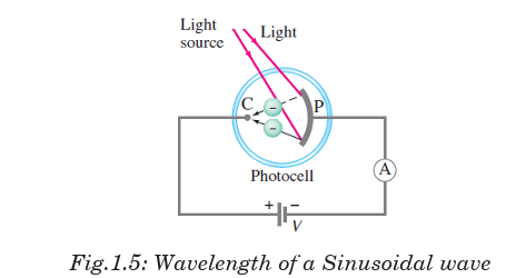
When the photocell is in the dark, the ammeter reads zero. But when light
of sufficiently high frequency illuminates the plate, the ammeter indicates
a current flowing in the circuit across the gap between P and C. This effect
is called the photoelectric effect and it occurs in many materials, but is
most easily observed with metals.
We explain completion of the circuit by imagining that electrons, ejected
from the plate by the impinging light, flow across the tube from the plate P
to a positive electrode called the “collector” C and cause a current to register
on the ammeter A as indicated in Fig. 1.5.
Photocurrent is the current that flows through a photosensitive device,
such as a photodiode, as the result of exposure to radiant power. The photo
current may occur as a result of the photoelectric, photo emissive or photovoltaic effect.
1.3 PROPERTIES OF A LIGHT WAVE
The properties of waves include the following:
The wavelength of a wave is defined as the distance over which the wave’s
shape repeats.
It is the distance between the corresponding points on successive cycles,
eg. the distance between two wave crests is known as wavelength of a
sinusoidal wave. It is measured in units of length (metres, nanometres).
The wavelength is usually represented by the symbol (lambda).
A measurement of the wavelength is made by observing the wave in spaceat a single instant of time.
Amplitude: The maximum displacement of wave quantity relative to the
undisturbed, equilibrium position of a particle is called amptitude. for
example, height of water wave, pressure of sound wave, maximum electric
field, etc.
Periodic time: This is the time between two successive wave crests or
successive wave troughs. It is measured in units of time (second). The period
is often represented by the letter T. It is measured by observing the wave
displacement at a single point in space.
Frequency: The number of cycles per second of the wave quantity, measured
in hertz (Hz) is called frequency. The frequency is usually represented by
the letter f. The observation of the frequency is made at a single point inspace.
Phase angle: The number of units of angular measure between a point on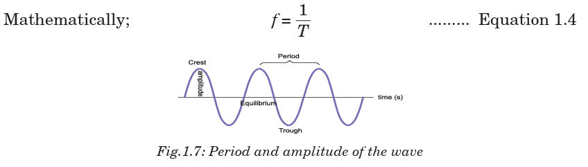
the wave and a reference point in a periodic wave is called phase angle.
The phase angle at any point is calculated using simple proportions as
shown below. Where is the wavelength, x is any horizontal distance
 and is the phase angle corresponding to the horizontal displacement.
ACTIVITY 1-1: Properties of waves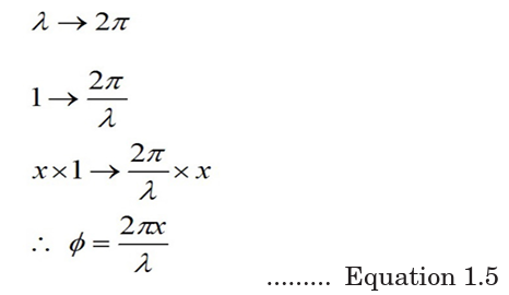
The curve of Fig.1.9 shows thevariation of height reached by
a vibrating object against the
horizontal distance it can cover.
Study the curve and answer the
questions that follow.
From the graph find;
(a) The amplitude of the wave.
(b) The wavelength of the wave.
(c) What do we call point A?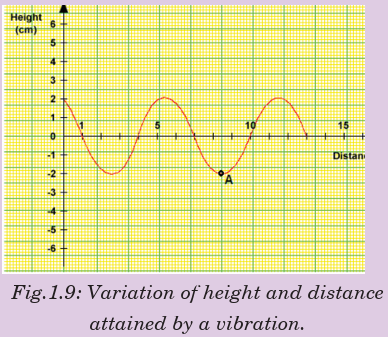
1.4 BLACKBODY RADIATION
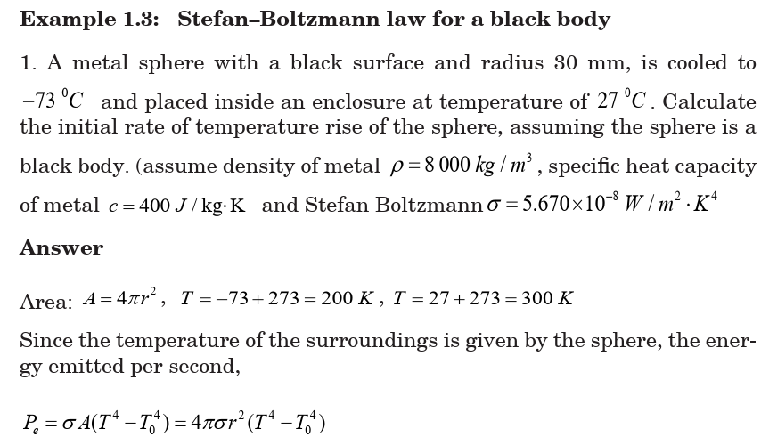
1.4.1 Stefan–Boltzmann law for a black body
By 1900 blackbody radiation had been studied extensively, and three
characteristics had been established in Stefan–Boltzmann law for a
black body:
All objects, no matter how hot or cold, emit electromagnetic radiation
(thermal radiation) whose total intensity I (the average rate of radiation
of energy per unit surface area per unit time or average power per area)
emitted from the surface of an ideal radiator is proportional to the fourthpower of the Kelvin (absolute) temperature.

1.4.2 Wien’s displacement law
Fig, 1.10 shows the measured spectral emittances for blackbody
radiation at three different temperatures. Each has a peak wavelength
at which the emitted intensity per wavelength interval is largest.
Experiment shows that is inversely proportional to T, so their product is
 constant. This observation is called the Wien displacement law.
The spectrum of the radiation depends on the temperature and the
properties of the object.
At normal temperatures we are not aware of this electromagnetic radiation
because of its low intensity. At higher temperatures, there is sufficient
infrared radiation that we can feel heat if we are close to the object. At still
higher temperatures (on the order of 1000 K), objects actually glow, such
as a red-hot electric stove burner or the heating element in a toaster. At
temperatures above 2000 K, objects glow with a yellow or whitish color,such as white-hot iron and the filament of a light bulb
The spectrum of light emitted by a hot dense object is shown in Fig. 1.10 for
an idealized blackbody. The radiation such an idealized blackbody would
emit when hot and luminous, called blackbody radiation (though not
necessarily black in color), and approximates that from many real objects.
The 6000 K curve in Fig. 1.10, corresponding to the temperature of the
surface of the Sun, peaks in the visible part of the spectrum. For lower
temperatures, the total intensity drops considerably and the peak occurs
at longer wavelengths (or lower frequencies). This is why objects glow
with a red color at around 1000 K. Measured spectra of wavelengths and
frequencies emitted by a blackbody at three different temperatures.
Example 1.4: The Sun’s surface temperature and temperature
1. Estimate the temperature of the surface of our Sun, given that the Sun
emits light whose peak intensity occurs in the visible spectrum at around
500 nm.
AnswerWe assume the Sun acts as a blackbody, and use in Wien’s law (Eq. 1.08).
Application Activity 1.2
1. Electromagnetic radiations are emitted by which of the following?
a. Only by radio and television transmitting antennas
b. Only bodies at temperature higher than their surrounding
c. Only by red-hot bodiesd. By all bodies
2. Which of the following statements is true regarding how blackbody
radiation changes as the temperature of the radiating object
increases?
a. Both the maximum intensity and the peak wavelength
increase.
b. The maximum intensity increases, and the peak wavelength
decreases.
c. Both the maximum intensity and the peak wavelength
decrease.
d. The maximum intensity decreases, and the peak wavelength
increases.
3. Which of the following statements is true regarding how blackbody
radiation changes as the temperature of the radiating object
increases?
a. Both the maximum intensity and the peak wavelength
increase.
b. The maximum intensity increases, and the peak wavelength
decreases.
c. Both the maximum intensity and the peak wavelength
decrease.
d. The maximum intensity decreases, and the peak wavelength
increases.
4. A black body is one that
a. Transmit all incident radiations
b. Absorbs all incident radiations
c. Reflects all incident radiations
d. Absorbs, reflects and transmits all incident radiations
5. The black body spectrum of an object A has its peak intensity at
200 nm while that of another object of same shape and size has its
peak at 600 nm. Compare radiant intensities of the two bodies.
6. The sun emits mostly in the visible region. Compare the total
intensity of radiation emitted by a star of similar size as the sun
whose surface temperature is 7 200 K.
7. Estimate the radiant energy emitted by a blackbody at 6 000 K
8. The sun’s surface temperature is 5 700 K. How much power is
radiated by one square meter of the sun’s surface? Given that the
distance to earth is about 200 sun radii, what is the maximum power
possible from a one square kilometer solar energy installation?
ACTIVITY 1-2: Blackbody Rediation
Discuss blackbody radiation in group and ask questions.
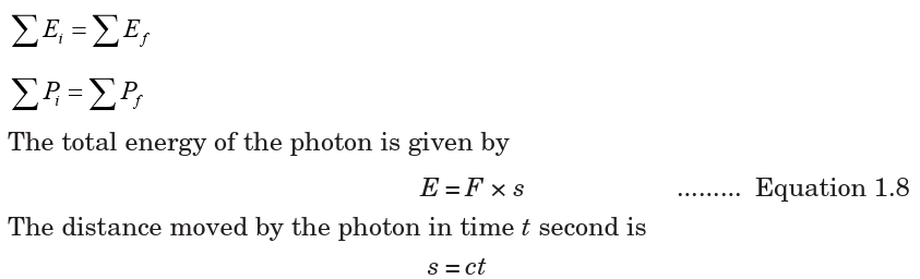
1.5 ENERGY, MASS AND MOMENTUM OF A PHOTON
The famous Einstein equation of energy of the photon is E = mc2. In short,
the equation describes how energy and mass are related with speed of light.
To derive this equation, consider an X-ray photon of mass m hitting the
surface of a metal and consider if a part of its energy is gained by a surface
electron and is then emitted.
The most important laws in dynamics are those that state the conservation
of energy and the conservation of momentum. These two laws can be applied
whenever we have a closed system; that is, a system that does not interact
with its surroundings. They assert that for such systems and any process
they may undergo. Assume that; E is the energy, s is the distance, F is theforce, c is the speed, t is the time, and P is the momentum

Application Activity 1.3
The mass of an electron or positron is 9.11 × 10⁻³¹ kg. The speed of light
is 3.0 × 10⁸ m/s.
1. Show that the rest energy of an electron is 8.2 × 10⁻¹⁴J.
2. Use the answer to question 1, to show that the rest energy of an
electron is 0.51 MeV.
3. Write down the rest energy of a positron (antielectron).
4. An electron and a positron meet and annihilate one another. By how
much does the rest energy decrease in total? Express the answer in MeV.
5. The annihilation of an electron and a positron at rest produces a pair
of identical gamma ray photons travelling in opposite directions.
Write down (in MeV) the energy you expect each photon to have.
6. A single photon passing near a nucleus can create an electron
positron pair. Their rest energy comes from the energy of the photon.
Write down the smallest photon energy that can produce one such pair.
7. Cosmic rays can send high-energy photons through the atmosphere.
What approximately is the maximum number of electron–positronpairs that a 10 GeV photon can create?
1.6 COMPTON EFFECT AND PHOTON INTERACTIONS
1.6.1 Compton effect
The Compton Effect concerns the inelastic scattering of X-rays by electrons.
Scattering means dispersing in different directions and inelastic means
that energy is lost by the scattered object in the process. The intensity of
the scattered X-ray is measured as a function of the wavelength shift.
Photons are electromagnetic radiation with zero mass, zero charge, and a
velocity that is always equal to the speed of light. Because they are electrically
neutral, they do not steadily lose energy via Coulombic interactions with
atomic electrons, as charged particles do. Photons travel some considerable
distance before undergoing a more “catastrophic” interaction leading to
partial or total transfer of the photon energy to electron energy. These
electrons will ultimately deposit their energy in the medium. Photons are
far more penetrating than charged particles of similar energy. There are
many types of photon interactions. We will only discuss those that are
important in radiation therapy and/or diagnostic radiology.
1.6.2 Types of photon interactions
Coherent scattering
Coherent scattering is one of three forms of photon interaction which occurs
when the energy of the X-ray or gamma photon is small in relation to the
ionisation energy of the atom. It therefore occurs with low energy radiation.
Upon interacting with the attenuating medium, the photon does not have
enough energy to liberate the electron from its bound state (i.e. the photon
energy is well below the binding energy of the electron), so no energy transfer
occurs. The only change is a change of direction (scatter) of the photon,
hence it is called ‘unmodified’ scatter. Coherent scattering is not a major
interaction process encountered in radiography at the energies normally
used. There are two types of coherent scattering: Thomson scattering and
Rayleigh scattering.
• In Thomson scattering, only one electron of the atom is involved in the
interaction.
• With Rayleigh scattering, all the electrons of the atom, sometimes
called the electron cloud, are involved in a cooperative effort in the
interaction with the photon.
Photoelectric effect
The following points make this phenomena clear:
1. The photon must have an energy equal to or greater than the binding2. The incident photon must be completely absorbed by the electron.energy of electron in the atom.
3. The electron is then ejected from the atom.
4. The excess energy over the binding energy is given to the electron in
the form of kinetic energy (which is the speed of the electron).
5. The hole left in the atom is filled by an outer shell electron or a free
electron with the emission of characteristic radiation.
Compton interaction
In Compton interaction, the photon interacts with a ‘free’ or an outer shell
electron. A portion of incident energy of the photon will be transferred to
an electron in the form of kinetic energy. The incident photon, now called
a scattered photon will be deflected in a new direction with less energy.
Energy given to recoil electron is considered as the absorbed energy and the
energy retained by the photon is considered scattered.
Pair Production
The photon interacts with the nuclear field of the atom, in such a way, that
the photon transforms itself into an electron-positron pair. As the photon
interacts with the strong electric field around the nucleus, it undergoes a
change of state and is transformed into two particles (essentially creating
matter from energy).Photodisintegration
(Photo transmutation) It is a nuclear reaction in which the absorption of
high energy electromagnetic radiation (a gamma-ray photon) causes the
absorbing nucleus to change to another species by ejecting a subatomic
particle, such as a proton, neutron, or alpha particle.
ACTIVITY 1-2: Compton Effect.
Aim: In this activity you will be able to highlight the most important terms
in Compton effect
Question: highlight at least 17 important terms you may need to explain
photoelectric effect and photo interaction. Use these terms to construct at
least 5 sentences to explain this theory 1.7 THE WAVE NATURE OF MATTERBeing fully aware of the pioneering work of Einstein on the photoelectriceffect, de Broglie extended the notion of wave particle duality to matter.
All matter can exhibit wave-like behaviour. For example, a beam of electron
can be diffracted just like a beam of light or a water wave.
The concept that matter behaves like a wave is also referred to de Broglie
hypothesis.
The de Broglie wavelength is the wavelength, , associated with a massive
particle and is related to its momentum p. With p being the particle’s momentum. The particles are diffracted bypassing through an aperture in a similar manner as light waves. The waveproperties of particles mean that when you confine it in a small space its
momentum and kinetic energy must increase.
 This wavelength is about the size of the interatomic spacing in solid andtherefore, leads to the observed diffraction effects.
b) de Broglie wavelength of the baseball: The de Broglie wavelength is very small as compared to the size of body.This why wave nature of matter is not noticeable in our diary life.
1.8 ELECTRON MICROSCOPE
A microscope can be defined as an instrument that uses one or several
lenses to form an enlarged (magnified) image. Microscopes can be classified
according to the type of electromagnetic wave employed and whether this
wave is transmitted or not through the specimen. The most common electron
microscopes are Transmission Electron Microscope (TEM) and Scanning
Electron Microscope (SEM). As it passes down through the tube the electron beam is controlled byelectromagnetic lenses formed by coils around the tube (whose effect ismoderated by adjusting the electricity flowing through the coils). These
electromagnetic lenses direct the electron beam through the centre of the
tube to a very thin specimen located part-way down the tube.
Some parts of the specimen might allow electrons to pass through them
unaffected. Other regions within the specimen absorb some or all of the
electrons that reach them. If any electrons continue from that part of the
specimen further down the tube to the image formation plane with less
energy. This happens because some of their energy has been absorbed by,
or “passed to”, the part of the specimen that the electron(s) passed through.TEM Applications• TEMs provide topographical, morphological, compositional and
crystalline information.
• It is useful in the study of crystals and metals, but also has industrial
applications.
• TEMs can be used in semiconductor analysis and the manufacturing
of computer and silicon chips.
• Tech giants use TEMs to identify flaws, fractures and damages to
micro-sized objects; this data can help and fix problems and/or help to
make a more durable efficient product.
• Colleges and universities can utilize TEMs for research and studies.
1.8.2 Scanning Electron Microscope (SEM)
The SEM is designed for direct study of the surfaces of solid objects. By
scanning with an electron beam that has been generated and focussed by
the operation of the microscope, an image is formed in the same way as a TV.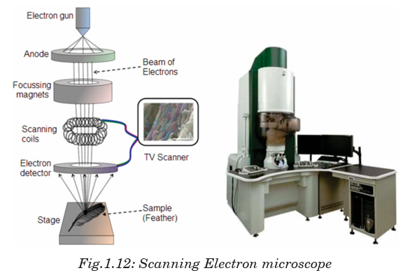 The SEM allows a greater depth of focus than the optical microscope. For this
reason, the SEM can produce an image that is a good representation of the
three-dimensional sample.
The SEM uses electrons instead of light to form an image. A beam of electrons
is produced at the top of the microscope by heating a metallic filament. The
electron beam follows a vertical path through the column of the microscope.
It makes its way through electromagnetic lenses which focus and direct the
beam down towards the sample. Once it hits the sample, other electrons
(backscattered or secondary) are ejected from the sample. Detectors collect
the secondary or backscattered electrons, and convert them to a signal that is
sent to a viewing screen similar to the one in an ordinary television, producingThe SEM allows a greater depth of focus than the optical microscope. For thisreason, the SEM can produce an image that is a good representation of the
three-dimensional sample.
The SEM uses electrons instead of light to form an image. A beam of electrons
is produced at the top of the microscope by heating a metallic filament. The
electron beam follows a vertical path through the column of the microscope.
It makes its way through electromagnetic lenses which focus and direct the
beam down towards the sample. Once it hits the sample, other electrons
(backscattered or secondary) are ejected from the sample. Detectors collect
the secondary or backscattered electrons, and convert them to a signal that is
sent to a viewing screen similar to the one in an ordinary television, producing
an image. To produce an image on the screen, the electron beam scans over
the area to be magnified and transfers this image to the TV screen.
Applications of SEM
• Image morphology of samples (eg. view bulk material, coatings,
sectioned material, foils, even grids prepared for transmission electron
microscopy).
• Image composition and finding some bonding differences (through
contrast and using backscattered electrons).
• Image molecular probes: metals and fluorescent probes.
• Undertake micro and nano lithography: remove material from
samples; cut pieces out or remove progressive slices from samples (eg.
using a focussed ion beam).
• Heat or cool samples while viewing them (it is generally done only in
ESEM or during Cryo-scanning electron microscopy).
• Wet and dry samples while viewing them (only in an ESEM)
• View frozen material (in an SEM with a cryostage)
• Generate X-rays from samples for microanalysis (EDS; WDS) to
determine chemical composition.
• Study optoelectronic behaviour of semiconductors using
cathodoluminescence
• View/map grain orientation/crystallographic orientation and study
related information like heterogeneity and microstrain in flat samples
(Electron backscattered diffraction).
• Electron diffraction using electron backscattered diffraction. The
geometry may be different from a transmission electron microscope
but the physics of Bragg Diffraction is the same.
END OF UNIT ASSESSMENT1. Hydrogen has a red emission line at 656.3 nm, what is the energy and
frequency of photon of this light?
2. An FM radio transmitter has a power output of 100 kW and operates
at a frequency of 94 MHz. How many photons per second does the
transmitter emit?
3. State Huygens’ principle. State its application and explain the
construction of spherical wavefront.
4. Determine the de Broglie wavelength for the following:a. A moving golf ball (m = 0.05 kg, 40 / v m s ),
b. An orbiting electron in the ground state of hydrogen
c. An electron accelerated through 100 kV in an electron microscope.
5. Determine the de Broglie wavelength of the matter wave associated with
a cricket ball of mass 0.175 kg and velocity 23.6 m/s. Use the answer
to this question to explain why we do not observe the matter waves
associated with macroscopic objects.6. Blue light of frequency 7.06 × 10¹⁴ Hz shines on sodium. Calculate the
maximum energy of the photoelectrons released.7. The range of frequency of ultraviolet rays is 7.9 × 10¹⁴ Hz to 5×10¹⁷ Hz.
What is corresponding range of energies of the photons of ultraviolet light? (Plank’s constant
8. Estimate how many visible light photons a 100 W light bulb emits per
second. Assume the bulb has a typical efficiency of about 3% (that is,
97% of the energy goes to heat).9. The following phenomena prove that light can behave like either a particle
or a wave: Reflection of light, refraction of light, interference of light,
photoelectric effect, Compton effect
a. What phenomena best prove that light is a particle instead of wave?
b. What phenomena best prove that light is a wave instead of particle?
10. One hundred years ago, Albert Einstein explained the photoelectric effect.
a. What is the photoelectric effect?
b. Write down an expression for Einstein’s photoelectric law.
c. Summarise Einstein’s explanation of the photoelectric effect
d. Give one application of the photoelectric effect.
11. Outline the advantages of Huygen’s wave theory of light.
12. If you pick up and shake a piece of metal that has free electrons, no
electrons fall out. Yet if you heat the metal, electrons can be boiled off.
Explain both of these facts and relate to the amount and distribution of
energy involved with shaking the object as compared with heating it.
13. Which formula may be used for the momentum of all particles, with or
without mass?
14. Is there any measurable difference between the momentum of a photon
and the momentum of matter?
15. Describe one type of evidence for the wave nature of matter.
16. Describe one type of evidence for the particle nature of EM radiation.
UNIT SUMMARY
Wave theory of monochromatic light: If light consists of undulations in
an elastic medium, it should diverge in every direction from each new centre
of disturbance, and so, like sound, bend round all obstacles and obliterate
all shadow.
A wave is any disturbance that results into the transfer of energy from one
point to another point.
Primary source: The geometrical centre or axis of the actual source of
light which is either a point or a line is called the primary source.
Wavelets: All points lying on small curved surfaces that receive light at the
same time from the same source (primary or secondary) are called wavelets.
Secondary source: Any point on a wavelet, acts as the source of light for
further propagation of light. It is called a secondary source.
Wavefront: The envelope of all wavelets in the same phase-receives light
from sources in the same phase at the same time is called a wavefront.
Wave normal: The normal at any point drawn outward on a wave front is
called the wave normal. Further propagation of light occurs along the wave
normal. In isotropic media the wave normal coincides with the ‘ray of light’.
A black body is a theoretical object that absorbs 100% of the radiation
that hits it and re-radiates energy which is characteristic of this radiatingsystem or body only.
The mass, energy and momentum of a photon are related according toequations;
Compton effect says that when X-rays are projected on the target, they
are scattered after hitting the target and change the direction in which they
were moving.
Photon interactions: because photons are electrically neutral, they do not
steadily lose energy via coulombic interactions with atomic electrons, as
do charged particles. Photon interactions include; Coherent Scattering,
Photoelectric Effect, Compton Interaction, Pair Production and
Photodisintegration.
Wave-particle duality of light: According to different experiments and
properties, light behaves as waves as well as particles.
Principle of complementarities: Both properties of light being a wave and
a particle are necessary to gaining complete knowledge of the phenomena;
they are complementary to each other but at the same time they also excludeeach other.
The wave nature of matter: The attribution of a wavelength to a massive
particle implies that it should behave as a wave under some conditions.
Electron microscope: is an instrument that uses one or several lenses to
form an enlarged (magnified) image. The most common electron microscopes
are Transmission Electron Microscopes (TEM) and Scanning ElectronMicroscope (SEM).
UNIT 2: SIMPLE HARMONIC MOTION
Key unit competence: By the end of the unit I should be able to
analyze energy changes in simple harmonic motion.
Unit Objectives:
By the end of this unit I will be able to;
◊ Determine the periodic time of an oscillating mass by practically
and by calculation accurately.
◊ Derive and apply the equation of simple harmonic motion correctly◊ Determine the periodic time of the simple pendulum correctly.
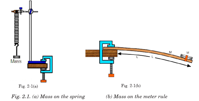
Introductory Activity
a. Clearly analyze the images of Fig. 2-1 given below and explain
what you think would happen in each case when the mass is displaced.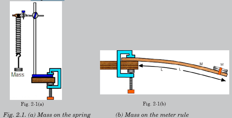
b. Basing on your daily experiences, what other systems do you
think behave the same way as fig 2.1(shown above) when displaced?
c. Discuss fields where those systems you mentioned in b) aboveare applied.
2.0 INTRODUCTION
You are familiar with many examples of repeated motion in your daily
life. If an object returns to its original position a number of times, we call
its motion repetitive. Typical examples of repetitive motion of the human
body are heartbeat and breathing. Many objects move in a repetitive way,
such as a swing, a rocking chair and a clock pendulum. Probably the first
understanding of repetitive motion grew out of the observations of motion
of the sun and phases of the moon.
Strings undergoing repetitive motion are the physical basis of all string
musical instruments. What are the common properties of these diverse
examples of repetitive motion?
In this unit we will discuss the physical characteristics of repetitive
motion and develop techniques that can be used to analyze this motionquantitatively.
Opening question
Clearly analyze the images of Fig. 2-1 given below and explain what youthink will happen in each case when the mass is displaced.
2.1 KINEMATICS OF SIMPLE HARMONIC MOTION
One common characteristic of the motions of the heartbeat, clock pendulum,
violin string and the rotating phonograph turntable is that each motion has
a well defined time interval for each complete cycle of its motion. Any motion
that repeats itself with equal time intervals is called periodic motion. Its
period is the time required for one cycle of the motion.
In Mechanics we showed that simple harmonic motion occurs when the
force acting on an object or system is directly proportional to its displacement x
from a fixed point and is always directed towards this point:
The negative sign in Eq. 2.01 implies that the force is opposite to the dis
placement.
To stretch the spring a distance x, an (external) force must be exerted onthe free end of the spring with a magnitude at least equal to.
The greater the value of k, the greater the force needed to stretch a spring
a given distance. That is, the stiffer the spring, the greater the spring constant k.
Consider a physical system that consists of a block of mass m attached to
the end of a spring, with the block free to move on a horizontal, frictionless
surface (Fig. 2.2). When the spring is neither stretched nor compressed, the
block is at the position called the equilibrium position of the system. If disturbed from its equilibrium position such a system oscillates back and forth.
Fig.2. 2 A block attached to a spring moving on a frictionless surface. (a) When the block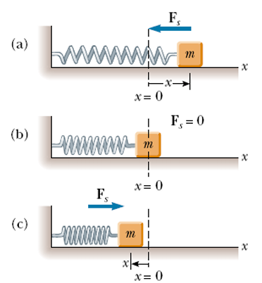
is displaced to the right of equilibrium (x > 0 ), the force exerted by the spring acts to
the left. (b) When the block is at its equilibrium position (x =0 ), the force exerted by the
spring is zero. (c) When the block is displaced to the left of equilibrium (x < 0 ), the forceexerted by the spring acts to the right.
Recall that when the block is displaced a small distance x from equilibrium,
the spring exerts on the block a force that is proportional to the displace
ment and given by Hooke’s law (Eq. 2.01).
We call this a restoring force because it is always directed toward the
equilibrium position and therefore opposite the displacement. That is, when
the block is displaced to the right of in Figure above, then the displacement
is positive and the restoring force is directed to the left. When the block is
displaced to the left of then the displacement is negative and the restoring
force is directed to the right.
Applying Newton’s second law to the motion of the block, together withEquation 2.01, we obtain.

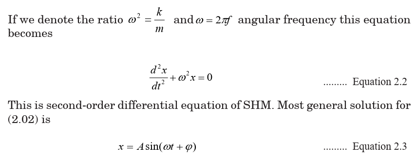
Fig.2. 3 Defining the phase angle for a sinusoidal function that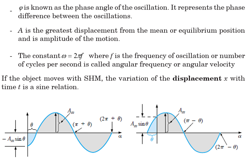
crosses the horizontal axis with a positive slope after 0°
We can obtain the linear velocity of a particle undergoing simple harmonic
motion by differentiating Equation 2.03 with respect to time:
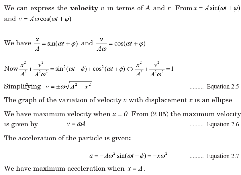
From this equation we see that the acceleration is proportional to the
displacement of the body, and its direction is opposite the direction of the
displacement. Systems that behave in this way are said to exhibit simple
harmonic motion.
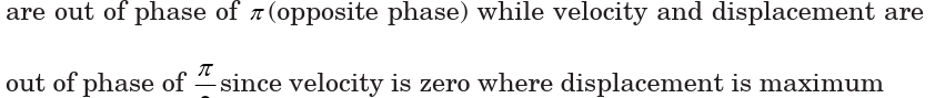
The curves in Fig.2.4 show that at the time of zero velocity 2.4a, the acceleration
and the displacement are maximum. At a time of maximum velocityFig.2.4b, the acceleration and the displacement are zero. We say that they


EXAMPLE 2.1
A particle moving with SHM has velocities 4 cm/s and 3 cm/s at distances
3 cm and 4 cm respectively from equilibrium position. Find
(a) the amplitude of oscillation
(b) the period(c) velocity of the particle as it passes through the equilibrium position.

EXAMPLE 2.2
A simple pendulum has a period of 2.0 s and amplitude of swing 5.0 cm.
Calculate the maximum magnitude of
(a) velocity of the bob
(b) acceleration of the bob.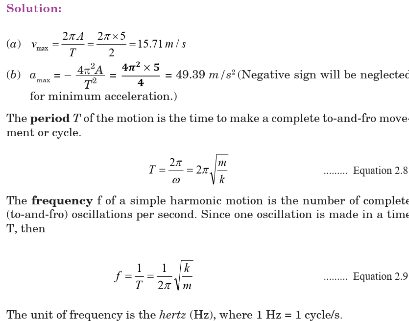
The frequency and period depend only on the mass of the block and on the
force constant of the spring. Furthermore, the angular frequency, the frequency
and period are independent of the amplitude of the motion
EXAMPLE 2.3: PERIOD, FREQUENCY, AND ANGULAR FREQUENCY
1. A car with a mass of 1 300 kg is constructed so that its frame is supported
by four springs. Each spring has a force constant of 20 000 N/m.
(a) If two people riding in the car have a combined mass of 160 kg, find the
frequency of vibration of the car after it is driven over a pothole in the road
and what is the angular frequency.
(b) How long does it take the car to execute two complete vibrations?
Answer
We assume that the mass is evenly distributed. Thus, each spring supports
one fourth of the load. The total mass is 1 460 kg, and therefore each springsupports 365 kg.
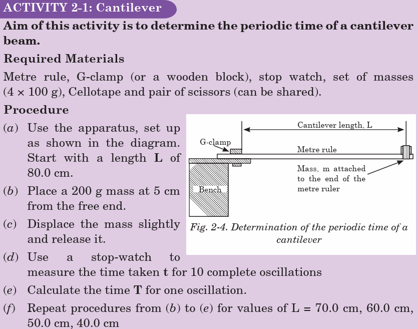
ACTIVITY 2-1: Cantilever
Aim of this activity is to determine the periodic time of a cantilever beam.
Required Materials
Metre rule, G-clamp (or a wooden block), stop watch, set of masses(4 × 100 g), Cellotape and pair of scissors (can be shared).

EXAMPLE 2-4The displacement of an object undergoing simple harmonic motion is given
Application Activity 2.1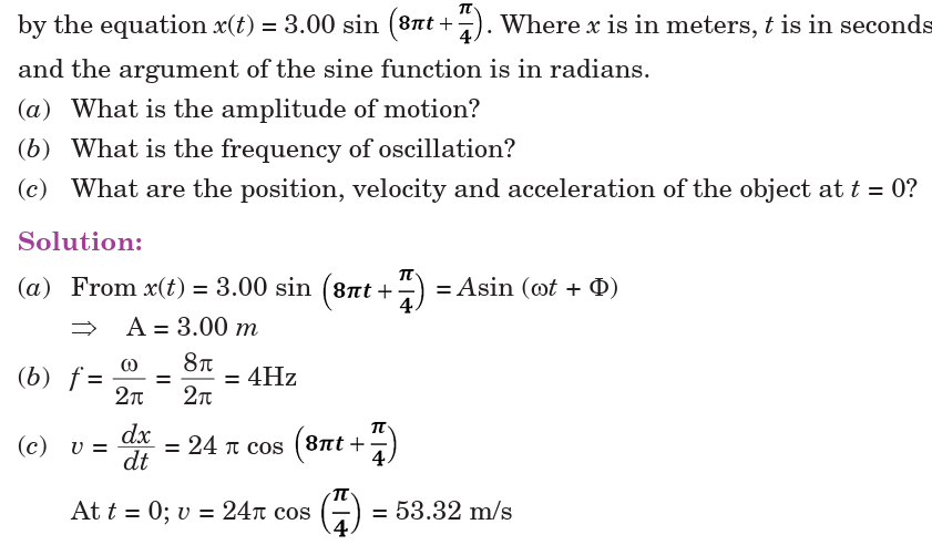
1. A body of mass 100 g undergoes simple harmonic motion with
amplitude of 20 mm. The maximum force which acts upon it is 0.05
N. Calculate:
(a) its maximum acceleration.
(b) Its period of oscillation.
2. The following graph shows the displacement (x) of a simple harmonic oscillator.
Draw graphs of its velocity, momentum, acceleration and the force acting on it.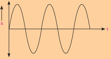
3. A particle undergoes SHM with an amplitude of 8.00 cm and an
angular frequency of 0.250 s-1. At t = 0, the velocity is 1.24 cm/s.
Determine:
(a) The equations for displacement and velocity of the motion.(b) The initial displacement of the particle.
2.2 SIMPLE HARMONIC OSCILLATORS
A simple harmonic oscillator is a physical system in which a particle
oscillates above and below a mean position at one or more characteristic
frequencies. Such systems often arise when a contrary force results from
displacement from a force-neutral position and gets stronger in proportion
to the amount of displacement. Below are some of the physical oscillators;
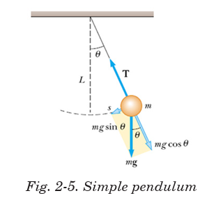
2.2.1 Simple Pendulum
A simple pendulum consists of a small bob of mass m suspended from a
fixed support through a light, inextensible string of length L as shown on
Fig.2-5. This system can stay in equilibrium if the string is vertical. This is
called the mean position or the equilibrium position. If the particle is pulled
aside and released, it oscillates in a circular arc with the center at the pointof suspension ‘O’.

Equation 2-12 shows that acceleration is directly proportional to displace
ment and is opposite to it. So the bob executes S.H.M;Comparing equation 2-7 and equation 2-12 gives
Equation 2-18 represents the periodic time of a simple pendulum. Thus, the
following are the factors affecting the periodic time of the simple pendulum;
• Length of string
• Acceleration due to gravity
EXAMPLE 2.5
A small piece of lead of mass 40 g is attached to the end of a light string of
length 50 cm and it is allowed to hang freely. The lead is displaced to 0.5 cm
above its rest position, and released.
(a) Calculate the period of the resulting motion, assuming it is simple
harmonic.
(b) Calculate the maximum speed of the lead piece. (Take g = 9.81 m.s–2)
Solutions:
(a) To calculate the time periodequation 2-26 can be used
EXAMPLE 2.6
What happens to the period of a simple pendulum if the pendulum’s length
is doubled? What happens to the period if the mass of the suspended bob isdoubled?
ACTIVITY 2-2: Acceleration due to Gravity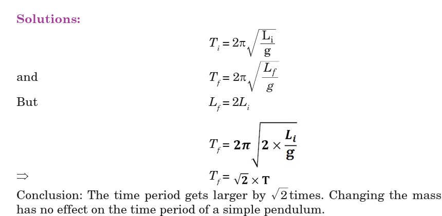
The aim of this activity is to determine the acceleration due togravity using oscillation of a simple pendulum Apparatus
2.2.2 Mass suspended from a Coiled Spring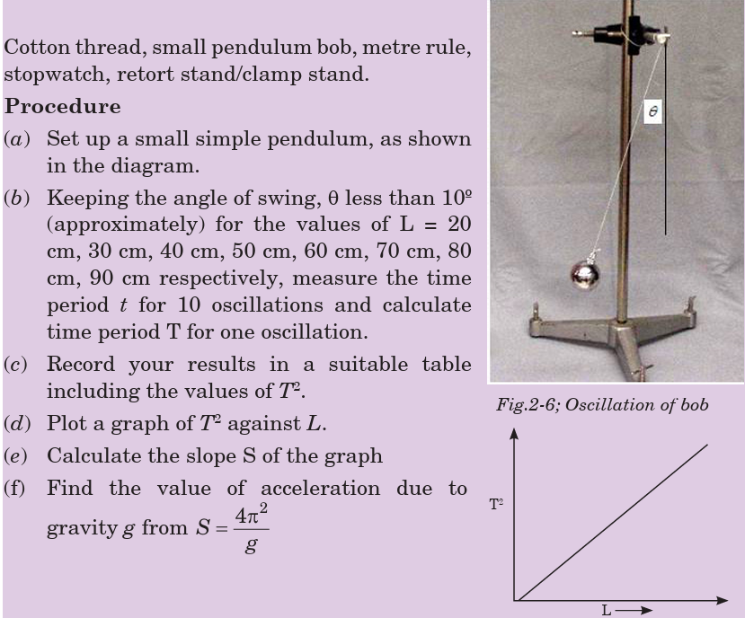
The extension of the spiral spring which obeys Hook’s law is directly
proportional to the extending tension. A mass m is attached to the end of
the spring which exerts a downward tension mg on it and stretches it by eas shown in Fig.2-7 below;

The stretching force is equal to the upward tension and is given by k(x + e)
So, the resultant force acting on the mass downwards is given by;F = Downword force – Upward force .
Form equation 2-17 and 2-18, we conclude that the periodic time of an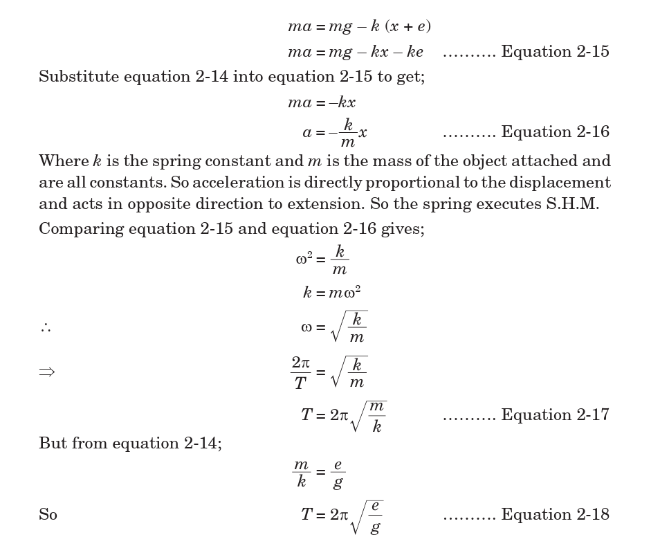
oscillation of a mass on a spring will depend on extension and the mass tied on it.
EXAMPLE 2.7
When a family of four with a total mass of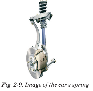
200 kg steps into their 1200 kg car, the car’s
springs get compressed by 3.0 cm.
(a) What is the spring constant of the car’s
springs (Fig.2-9), assuming they act as a
single spring?
(b) How far will the car lower if loaded with300 kg rather than 200 kg?
ACTIVITY 2-3: Acceleration due to Gravity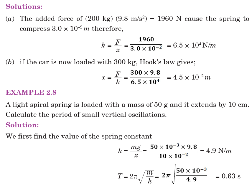
Aim: The aim of this activity is to determine the acceleration due to
gravity, g, using mass on spring.
Required materials1 retort stand, one spiral
spring, slotted masses (5 × 100g), 1 meter rule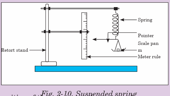
Procedure
(a) Clamp the given spring and a meter rule as shown in the
figure above.
(b) Read and record the position of the pointer on the meter rule.
(c) Place mass m equal to 0.100 kg on the scale pan and record the new
position of the pointer on the meter rule.
(d) Find the extension of the spring x in meters.
(e) Remove the meter rule
(f) Pull the scale pan downwards through a small distance and release it.
(g) Measure and record the time for 20 oscillations. Find the time T for
one oscillation.
Repeat the procedures (f) and (g) for values of m equal to 0.200 kg,
0.300 kg, 0.400 kg and 0.500 kg.
(i) Record your results in a suitable table including values of T2.
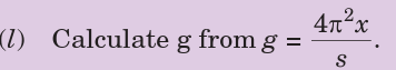
(j) Plot a graph of T2 (along the vertical axis) against m (along the horizontal axis).
(k) Find the slope, s, of the graph.
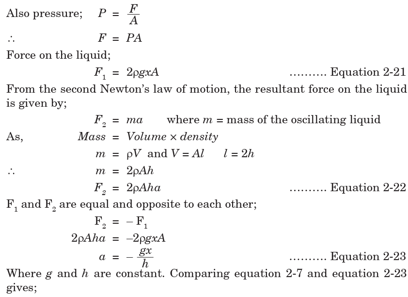
2.2.3 Liquid in a U-tube.
Consider a U-shaped tube filled with a liquid. If the liquid on one side of a
U-tube is depressed by blowing gently down that side, the level of the liquid
will oscillate for a short time about the respective positions O and C beforefinally coming to rest.


Application Activity 2.2
1. A baby in a ‘baby bouncer’ is a real-life example of a mass-on
spring oscillator. The baby sits in a sling suspended from a stout
rubber cord, and can bounce himself up and down if his feet are
just in contact with the ground. Suppose a baby of mass 5.0 kg is
suspended from a cord with spring constant 500 N m–1. Assume g =
10 N kg–1.
(a) Calculate the initial (equilibrium) extension of the cord.
(b) What is the value of angular velocity?
(c) The baby is pulled down a further distance, 0.10 m, and
released. How long after his release does he pass through
equilibrium position?
(d) What is the maximum speed of the baby?
(e) A simple pendulum has a period of 4.2 s. When it is shortened
by 1.0 m the period is only 3.7 s.
(f) Calculate the acceleration due to gravity g suggested by the
data.
2. A pendulum can only be modelled as a simple harmonic oscillator
if the angle over which it oscillates is small. Why is this so?
3. What is the acceleration due to gravity in a region where a simple
pendulum having a length 75.000 cm has a period of 1.7357 s?
State the assumptions made.
4. A geologist uses a simple pendulum that has a length of 37.10 cm
and a frequency of 0.8190 Hz at a particular location on the Earth.What is the acceleration due to gravity at this location?

6. A spring is hanging from a support without any object attached to it
and its length is 500 mm. An object of mass 250 g is attached to the
end of the spring. The length of the spring is now 850 mm.
(a) What is the spring constant?
The spring is pulled down 120 mm and then released from rest.
(b) Describe the motion of the object attached to the end of the spring.(c) What is the displacement amplitude?
2.3 KINETIC AND POTENTIAL ENERGY OF AN
OSCILLATING SYSTEM
Kinetic energy as the energy of a body in motion, change in velocity will also
change it as shown on Fig.2-12. Velocity of an oscillating object at any point
is given by equation: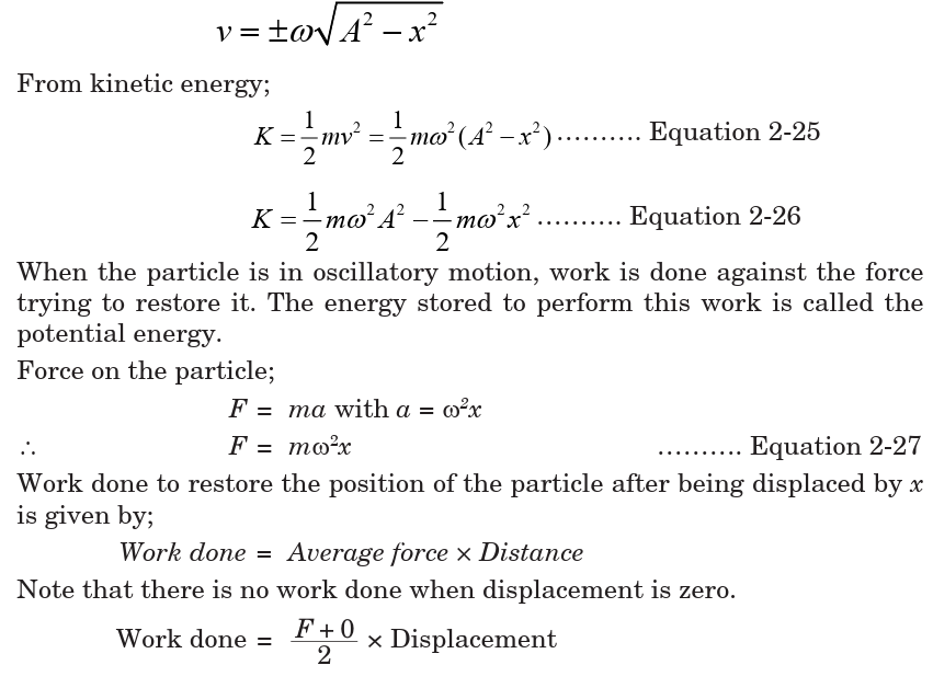
2.4 ENERGY CHANGES AND ENERGY CONSERVATION
IN AN OSCILLATING SYSTEM
In an oscillation, there is a constant interchange between the kinetic and
potential forms and if the system does no work against resistive force its
total energy is constant. Fig.2-12 illustrates the variation of potential
energy and kinetic energy with displacement x.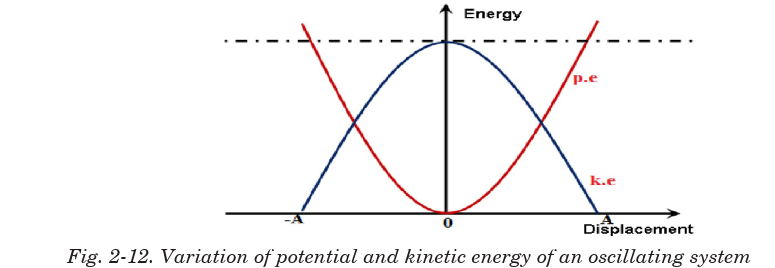
Substituting equation for sinusoidal displacement into equation 2-29 and
equation 2-30 gives;
is independent of displacement x. Since the total energy of an oscillating
particle is constant, it means that potential energy and kinetic energy vary
in such a way that total energy is conserved.
Also substituting equation 2-30 and equation 2-31 into equation 2-32 will
give an expression for the total energy of an oscillating system which isindependent of time taken.
EXAMPLE 2.9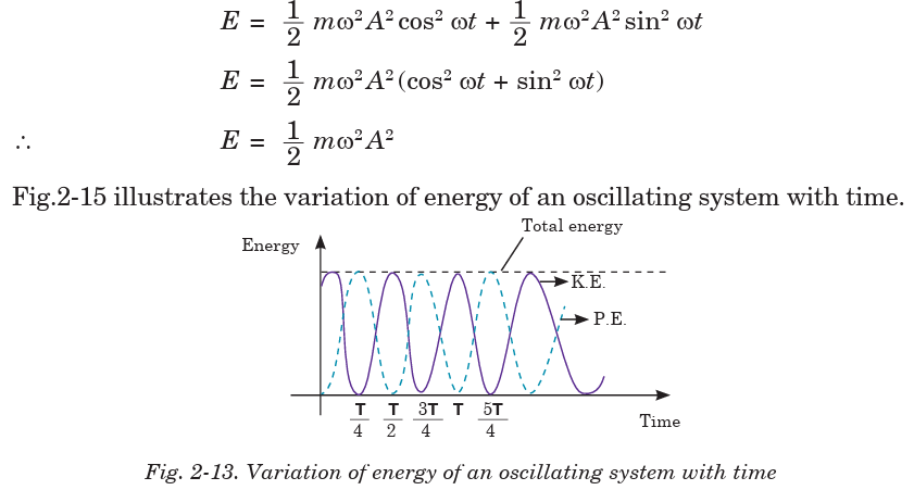
A 0.500 kg cart connected to a light spring for which the force constant is
20.0 N/m oscillates on a horizontal, frictionless air track.
(a) Calculate the total energy of the system and the maximum speed of the
cart if the amplitude of the motion is 3.00 cm.
(b) What is the velocity of the cart when the position is 2.00 cm?
(c) Compute the kinetic and potential energies of the system when the
position is 2.00 cm.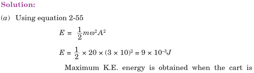

Application Activity 2.3
1.The graph in fig. below shows the variation with displacement of the
kinetic energy with displacement of a particle of mass 0.40 kgperforming SHM.
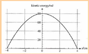
Use the graph to determine:
i. The total energy of the particle.
ii. The maximum speed of the particle.
iii. The amplitude of the motion.
iv. The potential energy when the displacement is 2.0 cm.
v. The period of the motion.
2. A 0.500-kg mass is vibrating in a system in which the restoring
constant is 100 N/m; the amplitude of vibration is 0.200 m.
Find
a. The PE and KE when x = 0.100 m
b. The mechanical energy of the system
c. The maximum velocity
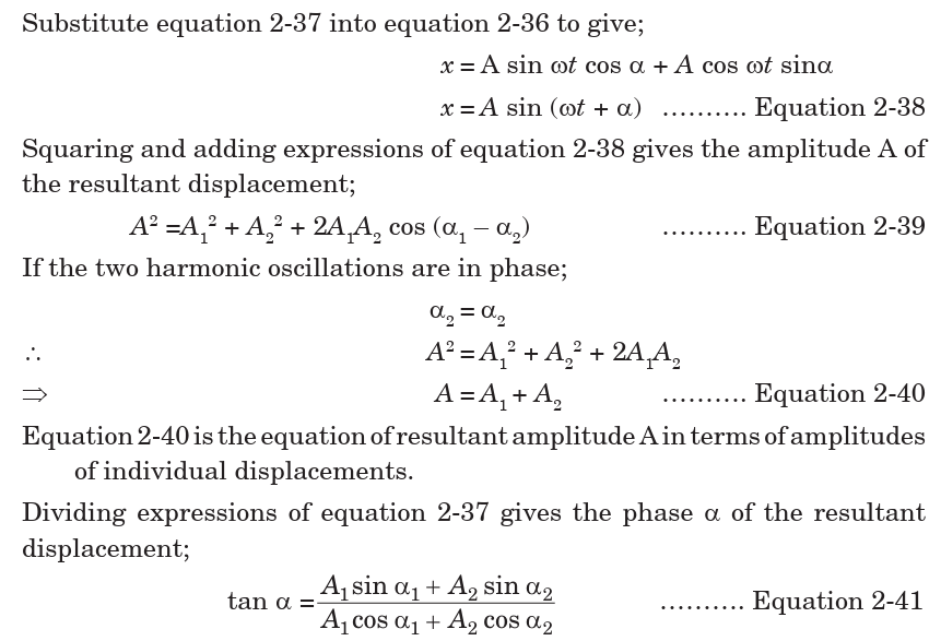
2.5 SUPERPOSITION OF HARMONICS OF SAMEFREQUENCY AND SAME DIRECTION
Consider two simple harmonic oscillations which interfere to produce a
displacement x of the particle along same line. Suppose that both have the
same frequency. The displacement time functions of respective motions are
given by equations 2-39 and 2-40 with A1 and A2 being the amplitude of
individual displacements ( x1and x2) and a1 and a2as their respective
phase angles;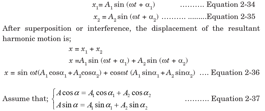
QUESTIONS
1. Give at least 2 examples of the applications of superposition in real life.
2. Derive the expression for the resultant displacement of two oscillations
of the same frequency but acting in opposite directions.
END OF UNIT ASSESSMENT
2. A 200 g block connected to a light spring for which the force constant
is 5.00 N/m is free to oscillate on a horizontal, frictionless surface. The
block is displaced by 5.00 cm from equilibrium and released from rest,as in Fig.2-15.
(a) Find the period of its motion.
(b) Determine the maximum speed of the block.
(c) What is the maximum acceleration of the block?
(d) Express the position, speed, and acceleration as functions of time.
3. (a) A 10 N weight extends a spring by 5 cm. Another 10 N weight is
added, and the spring extends another 5 cm. What is the spring
constant of the spring?
(b) A pendulum oscillates with a frequency of 0.5 Hz. What is the
length of the pendulum?
4. Christian Huygens (1629–1695), the greatest clockmaker in history,
suggested that an international unit of length could be defined as the
length of a simple pendulum having a period of exactly 1 s. How much
shorter would our length unit be had his suggestion been followed?
5. A simple pendulum is suspended from the ceiling of a stationary
elevator, and the period is determined. Describe the changes, if any, in
the period when the elevator
(a) accelerates upward,
(b) accelerates downward, and
(c) moves with constant velocity.
6. Imagine that a pendulum is hanging from the ceiling of a car. As the car
coasts freely down a hill, is the equilibrium position of the pendulum
vertical? Does the period of oscillation differ from that in a stationary car?
7. What is the acceleration due to gravity in a region where a simple
pendulum having a length 75.000 cm has a period of 1.7357 s?
UNIT SUMMARY
Simple Harmonic Motion: Any motion that repeats itself in equal time
intervals is called periodic motion with the force F acting on an object
directly proportional to the displacement x from a fixed point and is always
towards this point.
Periodic Time; is the time taken by the particle to complete one oscillation.
Frequency is defined as number of oscillations occur in one second f = 1/T.
Amplitude is the maximum displacement of the particle from its resting position.
Angular velocity (w): is the rate of change of angular displacement with time.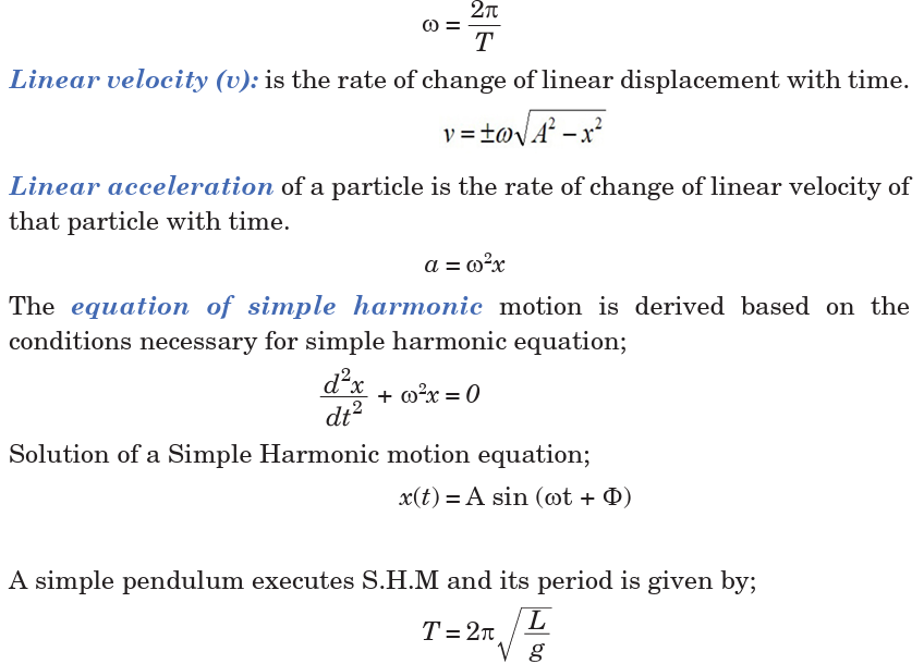
The extension of the spiral spring (caused by attached mass) which obeys
Hooke’s law is directly proportional to the extending tension. The periodic
time of oscillation caused by releasing the mass is given by;

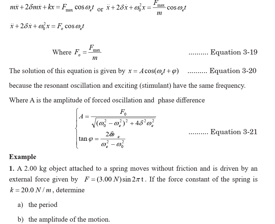
UNIT 3:FORCED OSCILLATIONS AND RESONANCE OF A SYSTEM
Key unit competence: Analyze the effects of forced oscillations on
systems..
Unit Objectives:
By the end of this unit I will be able to;
◊ Explain the concept of oscillating systems and relate it to the real
life situations.
◊ Solve equations of different types of damped oscillations and derive
the expression for displacement for each.
◊ explain resonance, state its conditions and explain its applicationsin everyday life.
Introductory Activity
Comment on the following situations by giving clear reasons on each;
• A guitar string stops oscillating a few seconds after being
plucked.
• To keep a child moving on a swing, you must keep pushing.
3.0 INTRODUCTION
In the conventional classification of oscillations by their mode of excitation,
oscillations are called forced if an oscillator is subjected to an external
periodic influence whose effect on the system can be expressed by a separate
term, a periodic function of the time, in the differential equation of motion.
We are interested in the response of the system to the periodic external
force. The behaviour of oscillatory systems under periodic external forces is
one of the most important topics in the theory of oscillations. A noteworthy
distinctive characteristic of forced oscillations is the phenomen of resonance,
in which a small periodic disturbing force can produce an extraordinarily
large response in the oscillator. Resonance is found everywhere in physics
and thus, a basic understanding of this fundamental problem is required.
3.1 DAMPED OSCILLATIONS.
Unless maintained by some source of energy, the amplitude of vibration of
any oscillatory motion becomes progressively smaller and the motion is said
to be damped. The majority of the oscillatory systems that we encounter
in everyday life suffer this sort of irreversible energy loss while they are in
motion due to frictional or viscous heat generation generally. We therefore
expect oscillations in such systems to eventually be damped.
Damping is the gradual decrease of amplitude of an oscillating system
due to presence of dissipative forces. As work is being done against
the dissipating force, energy is lost. Since energy is proportional to theamplitude, the amplitude decreases exponentially with time.
ACTIVITY 3-1: Resonance
Clearly observe the figure below and answer the questions thatfollow:
a) How is figure A different from B?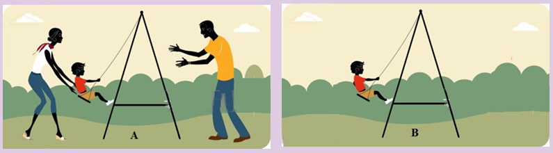
b) What do you think the kid is doing?
c) Assume that the man and woman shown are the kid’s father and
mother. What do you think they are doing?
d) Explain the oscillations in both cases.
e) Compare the two oscillations.
f) Depending on the definition of damping given above, how do you relate
it with the above scenarios?g) Make a clear conclusion.
In everyday life we experience some damped oscillations like:(i) Damping due to the eddy current produced in the copper plate

(ii) Damping due to the viscosity of the liquid
3.2 EQUATION OF DAMPED OSCILLATIONS
Consider a body of mass m attached to one end of a horizontal spring, the
other end of which is attached to a fixed point. The body slides back and
forth along a straight line, which we take as x-axis of a system of Cartesian
coordinates and is subjected to forces all acting in x-direction (they may be
positive or negative). The motion equations for constant mass are based
on Newton’s second law which can be expressed in terms of derivatives. In
all derivations assume that m is the mass of an oscillating object, b is thedamping constant and k is the spring constant.
Where b is the damping constant and the negative sign means that damping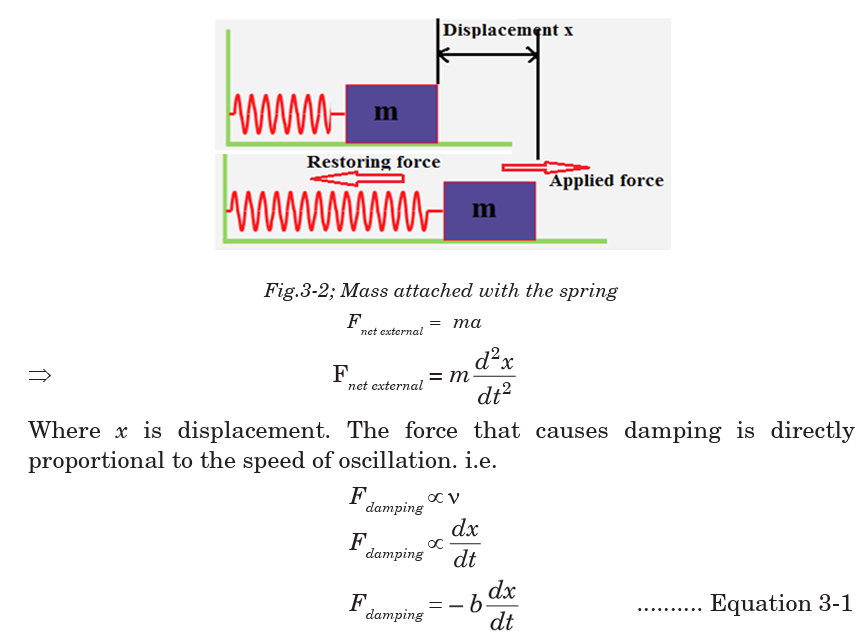
force always opposes the direction of motion of the mass.
The spring itself stores the energy that is used to restore the position of the
mass once released after being slightly displaced. The restoring force of thespring is directly proportional to the displacement.
Where k is the spring constant and the negative sign means that the restoring
force opposes the direction of motion of the mass. With this restoring forceand the resisting force of the spring, the resultant force on the mass is;
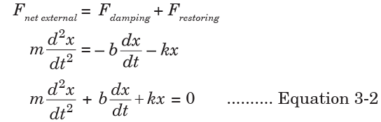
Equation 3.2 is the differential equation of damping.
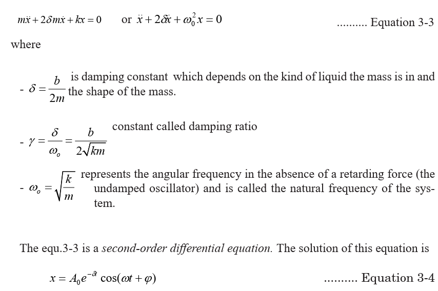
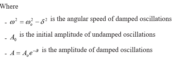
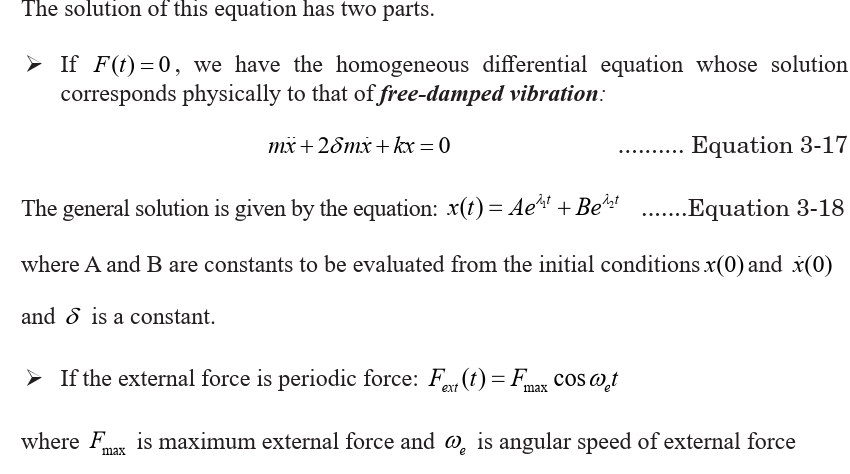
3.3 THE SOLUTION OF EQUATION OF DAMPINGIn terms of derivatives, the equation of damped oscillation is given by
We see that when the retarding force is small, the oscillatory character of the motion is
preserved but the amplitude decreases in time, with the result that the motion ultimately
ceases. Any system that behaves in this way is known as a damped oscillator.
Figure 3-3 shows the position as a function of time for an object oscillating in thepresence of a retarding force.
The dashed blue lines in Fig.3.3, which define the envelope of the oscillatory curve,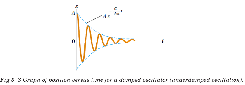
represent the exponential factor in Equation 3-4. This envelope shows that the amplitudedecays exponentially with time.

These cases are respectively classified as overdamped, critically damped, and
oscillatory damped (or, in electrical problems, underdamped) as shown in fig.3.4.

Let us consider these cases separately:
3.4.1 Overdamped or Heavy dampingOverdamped or Heavy damping is also called excessive damped oscillation and occur
A typical critically damped oscillation is shown in Fig. 3.4). A critically damped system
converges to zero as fast as possible without oscillating.
An example of critical damping is the door closer seen on many hinged doors in pub
lic buildings. An over-damped door-closer will take longer to close than a critically
damped door would.
Examples of Critical damping
(a) Shock Absorber
It critically damps the suspension of the vehicle and so resists the setting up
of vibrations which could make control difficult or cause damage. The viscousforce exerted by the liquid contributes to this resistive force.
(b) Electrical Meters They are critically damped (i.e. dead-beat) oscillators so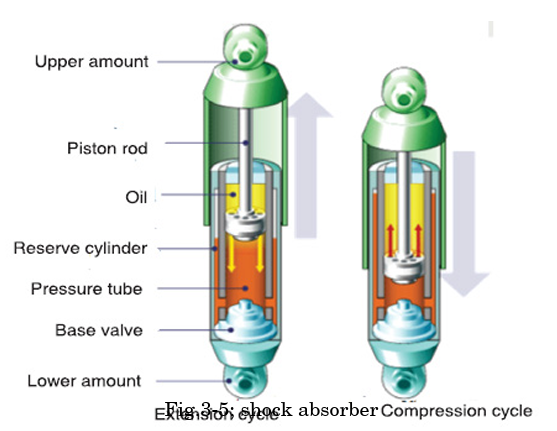
that the pointer moves quickly to the correct position without oscillation.

The system oscillates with the amplitude gradually (slowly) decreasing to zero. In
this situation, the system will oscillate at the natural damped frequency ωd
, which is a
function of the natural frequency and the damping ratio. This system stops after one or
two oscillations.
To continue the analogy, an underdamped door closer would close quickly, but would
hit the door frame with significant velocity, or would oscillate in the case of a swinging
door. Fig.3.4 depicts a typical underdamped response.
Examples of slightly damped oscillations include
Acoustics
(i) A percussion musical instrument (e.g. a drum) gives out a note whose intensity
decreases with time. (slightly damped oscillations due to air resistance)
(ii) The paper cone of a loud speaker vibrates, but is heavily damped so as to lose energy
(sound energy) to the surrounding air.
Plotting equations for damped oscillation on the same amplitude-time axes gives thegeneral curve for damping oscillation as shown on Fig.3-6.
Undamped oscillation (free oscillations): δ= 0
If the oscillating system is isolated (i.e. if no energy is being added to or taken away
from the system) the oscillations are called free oscillations. The system oscillates at
its natural resonant frequency ωo. Free Oscillations can occur whenever a restoring
force capable of transforming potential energy (PE) to kinetic energy (KE) and vice
versa is present. In a free oscillation, since the sum of the PE and KE cannot increase,
the PE must be largest at the extreme points of the oscillation where the KE is zero.
Examples
• Liquid sloshing mode - the restoring forces are due to gravity.
• A vibrating metal plate - elastic restoring forces.
• Stretched string - the restoring force is provided by tension in the string.
In each of these three examples all the oscillating particles together formed astanding wave pattern.
ACTIVITY 3-2 Damping Oscillation
A mass and spring system was set up with three masses of 100g and
radius 2.5 cm. The oscillator (masses) was displaced by 3 cm, released
and the time was measured for the oscillator to come to rest. After this,
pieces of circular cards were inserted between two of the masses and
the experiment was carried out again. Analyse the results obtained astabulated in table 3-1.
Analysis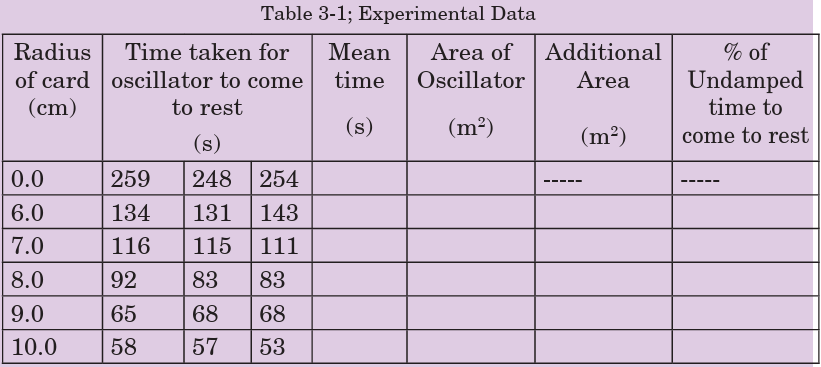
• Calculate mean value for the time taken for the oscillator to come
to rest for each radius of card.
• What is the uncertainty in the time taken to stop when the radius is 6 cm?
• Calculate this as a percentage of the mean value.
• What is the uncertainty in the time taken to stop when the radius is 8 cm?
• Calculate this as a percentage of the shortest time measurement at this radius.
• What is the uncertainty in the time taken to stop when the radius is 10 cm?
• Calculate this as a percentage of the longest time measurement at
this radius.
• What type of error is responsible for the difference in the value of
the time taken to come to rest?
• Calculate the area of the oscillator using A = . Write these values
in the column provided.
• What is the precision in the radius of card measurements?
• Calculate the percentage uncertainty in the 7.0 cm measurement.
• What will be the percentage uncertainty in the value of the area?
• Write down the upper and lower limits of the area.
• Plot a graph of radius of Oscillator (on the y axis) against time
taken to come to rest.
• Describe the graph you have plotted.
• What does your graph suggest about the relationship between the
two variables?
• Plot a graph of area of Oscillator (on the y axis) against time taken
to come to rest.
• Describe the graph you have plotted.
• What does your graph suggest about the relationship between
these two variables?
• Complete the final columns of the table by calculating the
additional area each card adds to the oscillator and the time period
as a percentage of the undamped time taken to come to rest.
• Do you notice any patterns or trends?
• Plot a graph of additional area (y axis) against percentage of
undamped time taken to come to rest.
• How are these variables linked?
• Theory states that damping will not affect the time period of the
SHM system. How could you prove this using the experimental setup described above?
3.5 NATURAL FREQUENCY OF A VIBRATION AND
FORCED OSCILLATION.
The natural frequency of an object is the frequency of oscillation when
released. e.g. a pendulum. A forced oscillation is where an object is subjected
to a force that causes it to oscillate at a different frequency than its natural
frequency. e.g. holding the pendulum bob in your hand and moving it along
its path either more slowly or more rapidly than its natural swing. Examples
on forced oscillation include:
A: Barton’s Pendulum
The oscillation of one pendulum by application of external periodic force
causes the other pendulums to oscillate as well due to the transfer of energy
through the suspension string. The pendulum having the same pendulum
length and pendulum bob mass will have the same natural frequency as
the original oscillating pendulum and will oscillate at maximum amplitude
due to being driven to oscillate at its natural frequency causing resonance to occur.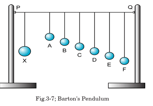
B: Hacksaw blade oscillator
This is another example of resonance in a driven system. If the peiod
of oscillation of the driver is changed by increasing the length of thread
supporting the moving mass, the hacksaw blade will vibrate at a different
rate. if we get the driving frequency right the slave will reach the resonant
frequency and vibrate widely. Moving the masses on the blade will have asimilar effect.
3.6 EQUATION OF FORCED OSCILLATION AND ITS SOLUTION
The mechanical energy of a damped oscillator decreases in time as a result of the resistive
force. It is possible to compensate for this energy decrease by applying an external force
that does positive work on the system. At any instant, energy can be transferred into the
system by an applied force that acts in the direction of motion of the oscillator.
For example, a child on a swing (se Fig.3.5) can be kept in motion by appropriately timed
“pushes.” The amplitude of motion remains constant if the energy input per cycle of
motion exactly equals the decrease in mechanical energy in each cycle that results from
resistive forces.
When a vibrating system is set into motion, it vibrates at its natural frequency
the resistive force decrease the amplitude because there is a loss of energy. To stop the
decrease of amplitude you must give an external energy to the system. The system that
gives energy is called excitatory and one receiving is called resonator. The resonator is
forced to oscillate at the frequency the external force and oscillation is forced.
Symbolically, it is designated by a dashpot, as shown in Fig. below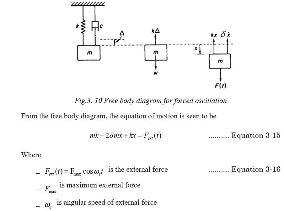
3.7. VARIATION OF FORCED FREQUENCY ON GRAPH AT
AMPLITUDE CLOSE TO NATURAL FREQUENCY OF VIBRATION.
If an oscillating object is made to perform forced oscillations, closer is the
frequency of force applied to the natural frequency, larger is the oscillation.
However the amplitude rises and falls as the object will be assisted to
oscillate for a short time and then the forces will oppose its motion for a short
time. The graph shows the variation of the amplitude of the oscillationswith time.
In figure 3.7, the applied force has a frequency closer to the natural
frequency. The amplitude of the oscillation has increased and there is timewhen the force helps and then hinders the oscillations.
The largest amplitude is produced when the frequency of the applied force
is the same as the natural frequency of the oscillation. When the energy
input from the applied force is equal to the energy loss from the damping,the amplitude stops increasing.
3.8 RESONANCE
When the frequency of excitatory is the same as that of resonator, then
the process is called resonance. The phenomenon of resonance is quicklyincreasing of amplitude when the frequency of exciting force approaches

3.9 APPLICATIONS AND EXAMPLES OF RESONANCE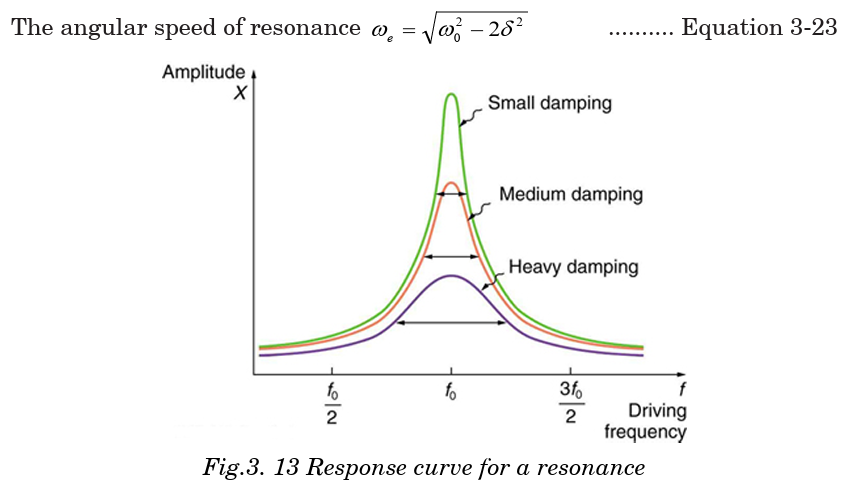
IN EVERYDAY LIFE
The phenomenon of resonance depends upon the whole functional form of
the driving force and occurs over an extended interval of time rather than
at some particular instant. Below are examples of resonance in different
applications;
3.9.1 A washing machine
A washing machine may vibrate quite violently at particular speeds. In
each case, resonance occurs when the frequency of a rotating part (motor,
wheel, drum etc.) is equal to a natural frequency of vibration of the body ofthe machine. Resonance can build up vibrations of large amplitude.
3.9.2 Breaking the glass using voice
Fig.3-14; A washing machine
You must have heard the story of an opera singer who could shatter a glass
by singing a note at its natural frequency. The singer sends out a signal
of varying frequencies and amplitudes that makes the glass vibrate. At
a certain frequency, the amplitude of these vibrations becomes maximum
and the glass fails to support it and breaks it. This scenario is shown onFig.3-10 below.
3.9.3 Breaking the bridge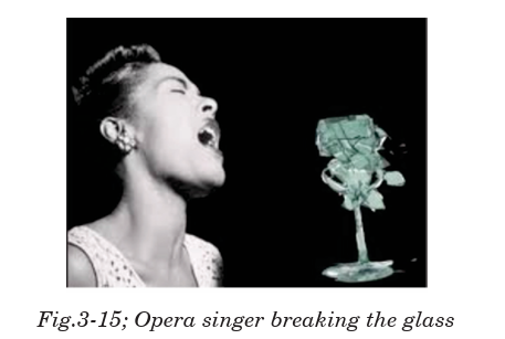
The wind, blowing in gusts, once caused a suspension bridge to sway with
increasing amplitude until it reached a point where the structure was over
stressed and the bridge collapsed. This is cuased by the oscillations of the
bridge that keep varying depending on the strength of the wind. At a certain
level, the amplitude of oscillation becomes maximum and develops crack onit and suddenly breaks.
3.9.4 Musical instruments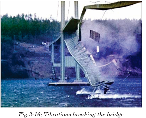
Wind instruments such as flute, clarinet, trumpet etc. depend on the idea
of resonance. Longitudinal pressure waves can be set up in the air inside
the instrument. The column of air has its own natural frequencies at
which it can vibrate. When we blow, we use the mouthpiece to start some
vibrations. Those which happen to match exactly the natural frequencies ofthe instrument are picked out and magnified.
3.9.5 Tuning circuit
The another example of useful resonance is the tuning circuit on a radio
set. Radio waves of all frequencies strike the aerial and only the one which
is required must be picked out. This is done by having a capacitance
inductance combination which resonates to the frequency of the required
wave. The capacitance is variable; by altering its value other frequenciescan be obtained.
3.9.6 Microwave Ovens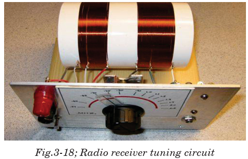
Microwave ovens use resonance. The frequency of microwaves almost
equals the natural frequency of vibration of a water molecule. This makes
the water molecules in food to resonate. This means they take in energy
from the microwaves and so they get hotter. This heat conducts and cooks the food.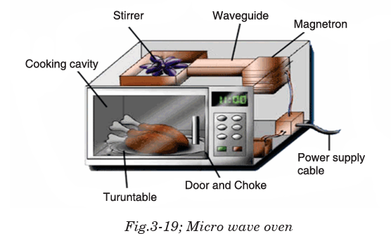
3.9.7 Magnetic Resonance Imaging (MRI)
The picture showing the insides of the body was produced using magnetic
resonance imaging (MRI). Our bodies contain a lot of hydrogen, mostly in
water. The proton in a hydrogen spins. A spinning charged particle has a
magnetic field, so the protons act like small magnets. These are normally
aligned in random directions. Placing a patient in a strong magnetic field
keeps these mini magnets align almost in line. Their field axis just rotateslike a spinning top. This is called processing.
3.10 EFFECT OF RESONANCE ON A SYSTEM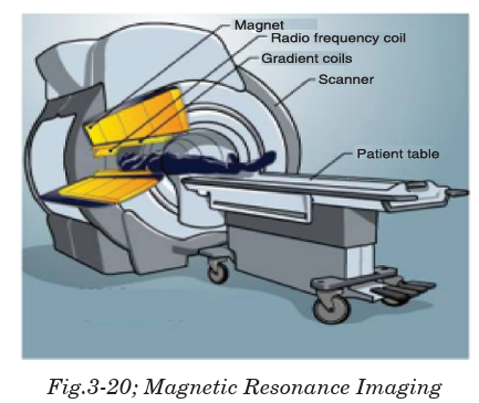
◊ Vibrations at resonance can cause bursting of the blood vessel.
◊ In a car crash a passenger may be injured because their chest is
thrown against the seat belt.
◊ The vibration of kinetic energy from the wave resonates through
the rock face and causes cracks.
◊ It is also used in a guitar and other musical instruments to
give loud notes.
◊ Microphones and diaphragm in the telephone resonate due to radio
waves hitting them.
◊ Hearing occurs when eardrum resonates to sound waves hitting it.
◊ Soldiers do not march in time across bridges to avoid resonance and
large amplitude vibrations. Failure to do so caused the loss of over two
hundred French infantry men in 1850.
◊ If the keys on a piano are pushed down gently enough it is possible to
avoid playing any notes. With the keys held down, if any loud noise
happens in the room (e,g. Somebody shouting), then some of the notes
held down will start to sound.
◊ An opera singer claims to be able to break a wine glass by loudlysinging a note of a particular frequency.
END OF UNIT ASSESSMENT
1. Solve the following initial value problem and determine the naturalfrequency, amplitude and phase angle of each solution.
2. Solve the following initial value problem. For each problem, determine
whether the system is under, over, or critically damped.
3. Consider a mass-spring system described by the equation
Give the value(s) of k for which the system is under, over, and critically
damped.
4. Damping is negligible for a 0.150 kg object hanging from a light 6.30
N/m spring. A sinusoidal force with an amplitude of 1.70 N drives the
system. At what frequency will the force make the object vibrate with an
amplitude of 0.440 m?
5. A 10.6 kg object oscillates at the end of a vertical spring that has a
spring constant of . The effect of air resistance is represented by the
damping coefficient . Calculate the frequency of the damped oscillation.
6. 1. A body of mass 0.5 kg suspended on a spring constant 50 N/m, describes
the damped oscillation with coefficient of resistance . At the upper end
it is applied the exciting force . Calculate the damping constant and the
amplitude of resonance of this system.
7. A body of mass 0.5 kg suspended on a spring constant 50 N/m, describes
the damped oscillation with coefficient of resistance . At the upper end
it is applied the exciting force . Calculate the damping constant and theamplitude of resonance of this system.
UNIT SUMMARY
Damping is a dissipating force that is always in the opposite direction
to the direction of motion of the oscillating particle and is represented by equation;
The natural frequency of an object is the frequency of oscillation when
released. e.g. a pendulum.
A forced oscillation is where an object is subjected to a force that causes it
to oscillate at a different frequency than natural frequency. It is representedby differential equation;
Resonance occurs when an object capable of oscillating, has a force applied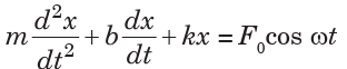
to it with a frequency equal to its natural frequency of oscillation. Resonance
occurs when angular frequency of oscillation is related to natural angularfrequency according to equation;
In real life, resonance is applied in;
• A washing machine
• Breaking the glass using the voice
• Breaking the bridge
• Musical instruments
• Tuning circuit
• Microwave ovens• Magnetic Resonance Imaging (MRI)
UNIT 4.PROPAGATION OF MECHANICAL WAVES
Key unit competence: By the end of the unit I should be able to
evaluate the propagation of mechanical waves.
Unit Objectives:
By the end of this unit I will be able to;
◊ Explain the terms, concept and characteristics of waves properly.
◊ Explain the properties of waves.
◊ Explain the behavior of waves in vibrating strings and applicationsof waves properly.
Introductory Activity
a. Arrange yourselves the form of a circle with your right
shoulders pointing towards the centre.
b. Ask your friend to raise arms and then lower them. Then the
next friend raises arms and lowers them, and so on around the
circle. It should be like the “wave”.
c. Describe the type of the disturbance formed.
d. Is the disturbance travelling up and down or horizontally
around the circle?
e. Let one of your friend gently push the back of the next student
and then the pushed member should gently push the next
member and so on, which will make a wave travel around the ring.
f. From what you have done, can you describe what a disturbance
is? Is the disturbance travelling up and down or around the ring?
4.0 INTRODUCTION
When we think of the word “wave”, we usually visualize someone moving
his hand back and forth to say ‘hello’ or maybe we think of a tall curling
wall of water moving in from the ocean to crash on the beach.
In physics, a wave is a disturbance that occurs in a material medium and
in such process, energy is transferred from one place to another. When
studying waves, it’s important to remember that they transfer energy, not matter.
There are lots of waves all around us in everyday life. Sound is a type of
wave that moves through matter and then vibrates our eardrums and we
hear. Light is a special kind of wave that is made up of photons that helps us
to see. You can drop a rock into a pond and see wave formation in the water.
We even use waves (microwaves) to cook our food really fast. Application ofthis concept is extensively used in telecommunication and music.
4.1 THE CONCEPT OF WAVES
Waves can be defined as a disturbance in a medium that transfers energy
from one place to another, although the medium itself does not travel.
The term wave is often intuitively understood as referring to a transport
of spatial disturbances that are generally not accompanied by a motion
of the medium occupying this space as a whole. In a wave, the energy of
a vibration is moving away from the source in the form of a disturbance
within the surrounding medium. Other properties, however, although
usually described in terms of origin, may be generalized to all waves. For
such reasons, wave theory represents a particular branch of physics that
is concerned with the properties of wave processes independently of their
physical origin.
4.2 TERMS USED AND CHARACTERISTICS OF WAVES
All waves are characterized by the following terms;
The Time period (T) of the wave is the time it takes for one wavelength of
the wave to pass a point in space or the time for one cycle to occur. It is also
defined as the time taken between two successive wave crests or trough. It
is measured in seconds (s).
The frequency (f) is the number of wavelengths that pass a point in
space per second. In another words, it can be defined as the number of
complete oscillations or vibrations per second. Its SI unit is hertz (Hz).Mathematically;
The wavelength
 is the horizontal distance in space between two nearest
points that are oscillating in phase (in step) or the spatial distance overwhich the wave makes one complete oscillation. Its SI unit is metre (m).
That is, wave speed = wavelength × frequency.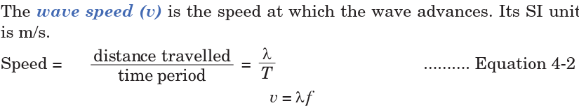
This is the relationship between wavelength, frequency and velocity.
Amplitude is defined as the maximum distance measured from equilibrium
position (mean position). The amplitude is always taken as positive and is
measured in metres.
Phase difference (phase angle) is the angular difference between two
points on the wave or between two waves. Consider, two points O and P on
the wave as shown in Fig. 4-12.Phase difference is a whole number and is calculated using simple proportions;
The wave number, also called the propagation number k, is the spatial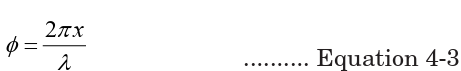
frequency of a wave, either in cycles per unit distance or radians per unit
distance. It can be envisaged as the number of waves that exist over a
specified distance (analogous to frequency being the number of cycles orradians per unit time). Its unit is per metre (m–1). Mathematically;
The Intensity (I) of a wave or the power radiated by a source are proportional
to the square of the amplitude (x).
I ∝ x2
Wavefront is a line or surface in the path of the wave motion on which the
disturbance at every point have the same phase. This can also be defined
as the surface which touches all the wavelets from the secondary sources ofwaves. Consider the Huygens construction principle for the new wavefront.
Crest is the highest point above the equilibrium position while trough is
the lowest point below then equilibrium position.
The angular frequency ω represents the frequency in radians per second. Itis related to the frequency by
A node is a point half way between the crest and the trough. The line that
connects the nodes is the nodal line. The nodal line shows the originalposition of the matter carrying the wave.
Application Activity 4.1
1. Requirements: a manila paper with the drawing of the waveshown below
a) How do you call the distance represented by arrow z?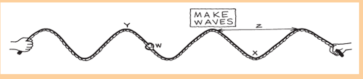
b) What letter is labelling the wave’s trough?
c) What letter is labelling a wave’s crest?
d) The number of waves that pass the poster per second is called
the …………….. of the waves.
e) If the knot (w) travels 2 meters in 1 second, we say that it has …………
….. of 2 m/s.
f) If the wavelengths were shortened, would the frequency be higher
or lower?
g) The greatest distance the knot (w) travels from its resting position
is called…………….. of the wave.h) What kind of wave are these in the rope?
2. Use the following descriptions in waves ad fill in the crosswordpuzzle bellow:
Across
1. How fast something is moving or how much distance is covered
in a certain amount of time.
3. The time it takes for a wave to repeat itself
4. The lowest point of a wave beneath the line of origin
9. Waves that require a medium
10. The highest point of a wave above the line of origin
11. Particles of light
12. A push or a pull
13. The tendency of an object at rest to remain at rest or in motion
until acted upon
Down
1. Waves that do not require a medium
2. The bouncing back of a wave when it meets the surface or boundary
3. The matter through which a wave travels
4. Distance in a given direction5. The vertical distance between the line of origin and the crest of a wave
4.3 TYPES OF WAVES
Waves are of three main types: Mechanical wave, electromagnetic wave
and matter wave.
These waves are classified based on conditions necessary for the wave to
propagate
4.3.1 Mechanical waves
These waves are produced by the disturbance in a material medium and
they are transferred by particles of the medium.
The matter through which mechanical waves travel is called the medium.
All mechanical waves require (1) some source of disturbance, (2) a medium
that can be disturbed, and (3) some physical mechanism through which
elements of the medium can influence each other.
Mechanical Waves are divided into two types according to the direction
of the displacements in relation to the direction of the motion of the wave
itself (wave form):
a) Longitudinal waves
When a wave propagates through some medium and the local displacements
of the medium that constitute the disturbance are in the direction of travel
of the disturbance, then the wave is longitudinal.
An example of a longitudinal wave is the pulse that can be sent along a
stretched slinky by shaking one end of the slinky along its length. The pulse
moves along the line of the slinky and ultimately makes the other end move.
Notice that in this case, the individual coils of the slinky vibrate back and
forth about some equilibrium position, but there is no net movement of theslinky itself.
b) Transverse waves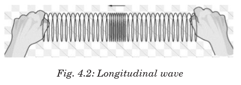
These are waves in which the direction of disturbance is perpendicular to
the direction of travel of the wave. The particles do not move along with the
wave; they simply oscillate up and down about their individual equilibriumpositions as the wave passes by.
4.3.1.4 Examples of mechanical waves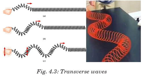
Mechanical waves, being progressive and stationary, are seen in different
forms as described in this section.
Sound waves
Sound waves are longitudinal waves. Sound waves travel fastest in solids,
slower in liquids and slowest in gases. This means the air particles (or
particles of the medium) move back and forth on paths that are parallel to
the direction of wave propagation and thus take the form of compressionsand rarefactions of the molecules in the air itself.
Water waves
Water waves are a combination of both transverse and longitudinal waves.
These waves are periodic disturbances that move away from the source andcarry energy as they go.
Ocean waves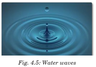
These waves are longitudinal waves that are observed moving through the
bulk of liquids, such as our oceans. Ocean waves are powerful forces that
erode and shape of the world’s coastlines. Most of them are created by the
wind. Winds that blow over the top of the ocean, create friction between
the air and water molecules, resulting in a frictional drag as waves on thesurface of the ocean.
Earthquake waves
Earthquakes occur when elastic energy is accumulated slowly within the
Earth’s crust (as a result of plate motions) and then released suddenly
along fractures in the crust called faults. Earthquake waves are also called
seismic waves and actually travel as both transverse and longitudinal waves.
The P waves (Primary waves or compressional waves) in an earthquake
are examples of longitudinal waves. The P waves travel with the fastestvelocity and are the first to arrive.
The S waves (Secondary waves or shear waves) in an earthquake are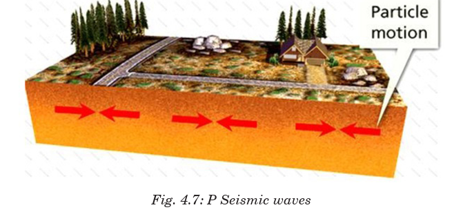
examples of transverse waves. S waves propagate with a velocity slowerthan P waves, arriving several seconds later.
Body Waves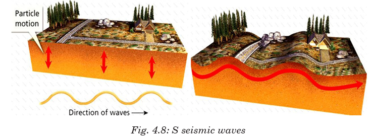
Body waves are of two types: compressional or primary (P) waves which
are longitudinal in nature and shear or secondary (S) waves which are
transverse in nature. P- and S- waves are called ‘body waves’ because they
can travel through the interior of a body, such as the Earth’s inner layers,
from the focus of an earthquake to distant points on the surface. The Earth’s
molten core are only travelled by compressional waves.
Surface Waves
When waves occur at or near the boundary between two media, a transverse
wave and a longitudinal wave can combine to form a surface wave.
Examples of surface waves are a type of seismic wave formed as a result ofan earthquake and water waves.
4.3.2 Electromagnetic waves
These waves consist of disturbances in the form of varying electric and
magnetic fields. No material medium is necessary for their movement andthey travel more easily in vacuum than in matter.
Examples of electromagnetic waves are: Radio waves, Microwaves, Infrared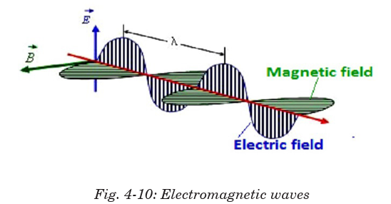
radiation, Visible light, Ultraviolet light, X-rays and Gamma rays. Thesewaves vary according to their wavelengths.
4.3.3 Matter Waves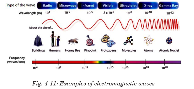
If we perform the double slit diffraction experiment using a beam of electrons instead of light,
we still get a diffraction pattern. The interpretation
of this is that matter travels as a wave. Thus “matter acts as both a
particle and as a wave.” If we can sometimes consider an electron to be a wave,
what is its wavelength? Louis de Broglie postulated that all particles withmomentum have a wavelength
The matter waves describe the wavelike characteristics of atomic-level
particles.
For mechanical waves, the speed of the wave is a property of the medium,
speed does not depend on the size or shape of the wave.
Example 4.11. Find de Broglie wavelength for
4.4 PROGRESSIVE WAVES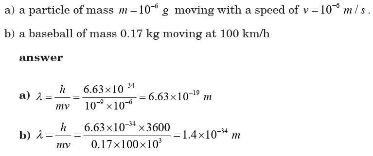
A progressive wave is also called a travelling wave which consists of
a disturbance moving from one point to another. As a result, energy
is transferred between points. Progressive mechanical waves can be
categorised according to the direction of the effect of the disturbance relative
to the direction of travel.
Equation of a progressive wave
An equation can performed to represent displacement
of a vibrating particle in a medium in which a wave passes. Suppose a wave moves from
left to right and that a particle at the origin moves with displacement givenby equation.
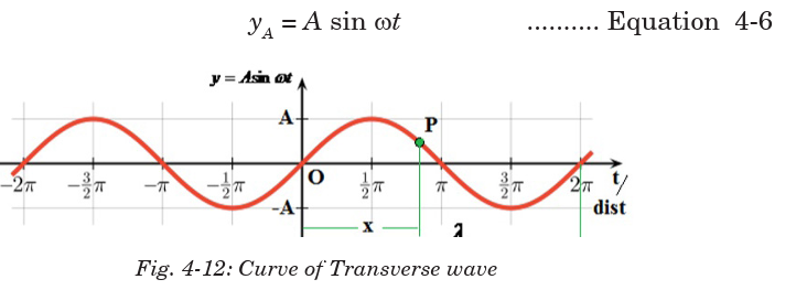
A particle at P will be out of phase from the particle at O, so, its displacement is given by;
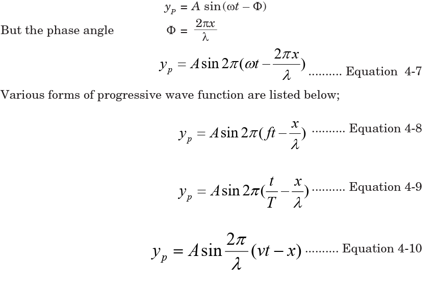

EXAMPLE 1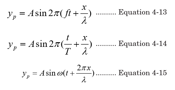
A travelling wave is described by the equation y(x, t) = 0.003 cos (20x + 200t)
where y and x are measured in metres and t in seconds. What is the direction
in which the wave is travelling? Calculate the following physical quantities:
(a) angular wave number
(b) wavelength
(c) angular frequency
(d) frequency
(e) time period
(f) wave speed
(g) amplitude
(i) particle acceleration when x = 0.3 m and t = 0.02 s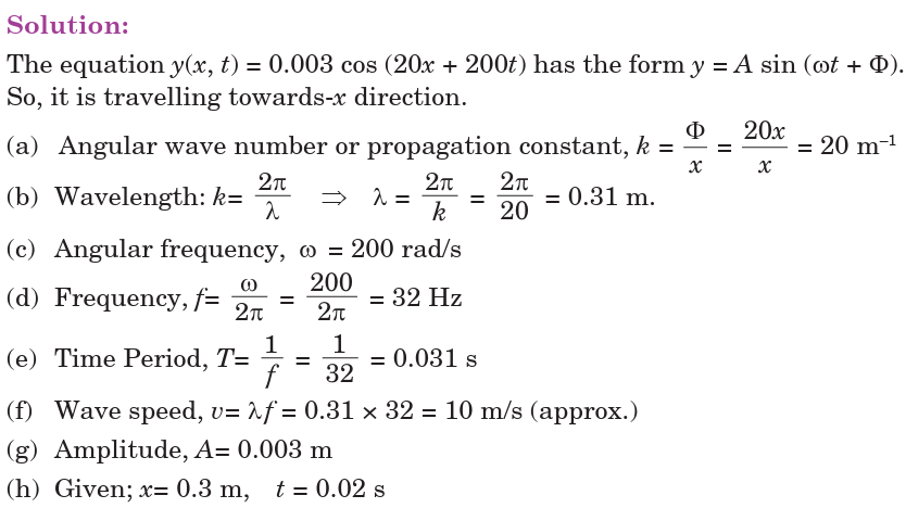

4.5 PRINCIPLE OF SUPERPOSITION
The displacement at any time due to any number of waves meeting
simultaneously at a point in a medium is the vector sum of the individual
displacements of each one of the waves at that point at the same time.
This means that when two waves travel in a medium, their combined effect
at any point can be determined using this principle. Consider two waves of
displacements y1 and y2
passing through the same medium. The resultant displacement after superposition is:
When two pulses of equal or different amplitudes on a string approach each
other, then on meeting, they superimpose to produce a resultant pulse of
amplitude greater than any of the two. After crossing, the two pulses travel
independently.
4.5.1 Stationary waves
A stationary wave (or a standing wave) is a wave which results when
two waves travelling in opposite directions and having the same speed,
frequency and approximately equal amplitudes are superposed. A standingwave is shown in Fig. 4.6 below.
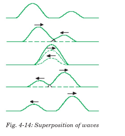
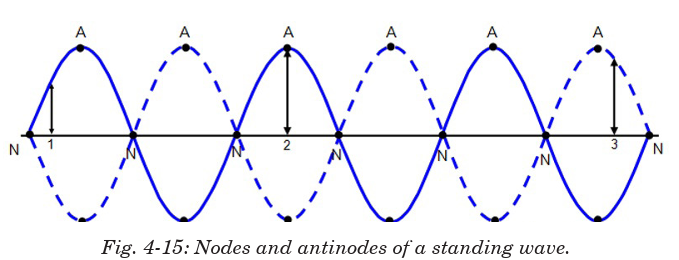
4.5.2 Mathematical treatment of superposition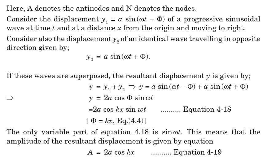
Position of nodesA node is defined as the point of zero amplitude. This means
Equation (4.21) means that nodes are obtained when the horizontal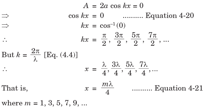
displacement of waves are odd quarter values of wavelength.
Position of antinodes
Antinodes are points of maximum displacements. So, antinodes are obtainedwhen the value of Equation 4.19 is maximum. This occurs when;
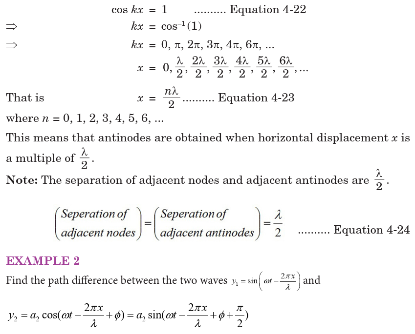

4.6 PROPERTIES OF WAVES
This section introduces the properties of waves and wave motion to describethe behaviour of waves in detail.
4.6.1 Reflection
This is the property of waves to bounce back from the surface on which they
hit. Huygens principle can also be applied to reflection. Consider a parallel
beam of light incident on the reflecting surface such that its direction oftravel makes an angle i with the normal to the surface.
Consider that side A of an associated wavefront AB has just reached the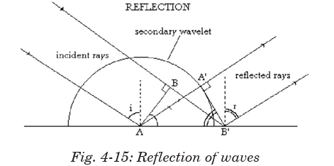
surface. In the time that light from side B of the wavefront travels to B′, a
secondary wavelet of radius equal to BB′ will be generated by A. Because
of the reflecting surface, this wavelet is a semicircle above the surface. The
new wavefront generated by reflection will be the tangent to this waveletand will also contain point B′. The reflected wavefront will be A′B′.
We conclude by saying that all laws of reflection are obeyed. So, any
wavefront can reflect.
4.6.2 Refraction
Consider a parallel beam of waves (for example light waves) incident ona refracting surface between two media such that its direction of travel

At the same time, wavelets from A travel distance AD in medium 2. Here, a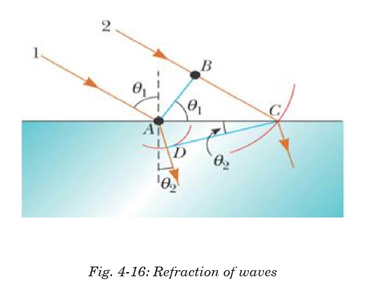
refracted wavefront CD is formed by many wavelets in the beam. Fig.4-16above illustrates this description.
Equation 4-32 confirms Snell’s law meaning that waves behave like normal
light during reflection.
4.6.3 Interference
In the region where wave trains from coherent sources (sources of the same
frequency) cross, superposition occurs giving reinforcements of waves at
some points which is called constructive interference and cancellation at
others which is called destructive interference. The resulting effect is calledinterference pattern or the system of fringes.
4.6.4 Diffraction
This is a phenomenon in which waves from one source meet an obstacle
and spread around it. Diffraction is normally observed when these waves
pass through narrow slits. There are two types of diffraction and these are;
Fresnel’s diffraction and Fraunhofer diffraction.
a) Fresnel’s diffraction
This is a type of diffraction in which either the source of waves or screen
on which diffraction is observed or both are at finite distances from the
obstacle that cause diffraction. Below are different cases to explain thisdiffraction.
Case 1: the source and the screen placed at finite distances.
Case 2: the source is placed at infinite distance from obstacle and the screen is near.
Case 3: the screen is placed at infinite distance from obstacle and the source is near.

b) Fraunhofer Diffraction
This is a type of diffraction in which the source of waves and the screen
on which diffraction is observed are effectively at infinite distances from
the obstacle. This phenomenon is practically complicated but theoretically
understood. To obtain waves to or from infinite source in laboratory,biconvex lenses are used.
4.7 WAVE ON A VIBRATING STRING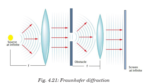
ACTIVITY 4-1: Propagation of Waves
Learning Objectives
• To observe the propagation of vibrations through a solid
• To understand how sound is transmitted through a medium
Required Materials
Spoon, string of length 1 m
Procedure
(a) Tie the spoon into the middle of the length of string so that it will hang
freely when you hold the string ends.
(b) Hold the string ends to your temples or the bone just under your earsas you strike the spoon with a pen or other object.
Discussion Questions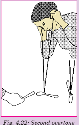
1. What causes the sound to be loud when the string is held to your head?
2. Why does the bone in front of your ear transmit vibrations more easily
than other bones?
3. What is the purpose of the string in this activity?
Standing wave also known as a stationary wave, is wave pattern that
results when two waves of the same frequency; wavelength and amplitude
travel in opposite directions along string and interfere.
The point at which the two waves cancel are called node. There no motion in
the string at the nodes, but midway between two adjacent nodes, the string
vibrates with the largest amplitude. These points are called antinodes. Atpoints between successive nodes the vibrations are in phase.
A single loop corresponds to either a crest or tough alone, while two loops
correspond to a crest and trough together, or one wave length.
Stationary waves are present in the vibrating strings of musical instruments.
A violin string, for instance, when bowed or plucked, vibrates as a whole,
with nodes at the ends, and also vibrates in halves, with a node at the center,
in thirds, with two equally spaced nodes, and in various other fractions, all
simultaneously. The vibration as a whole produces the fundamental tone,
and the other vibrations produce the various harmonics.
Standing waves can occur at more than one frequency. The lowest
frequency of oscillation that produces a standing wave gives rise to the
pattern shown in Fig. 4.24b. The standing waves shown in Figs. 4.24c and4.24d are produced at precisely twice and three times the lowest frequency,
respectively, assuming the tension in the cord is the same. The cord can also
oscillate with four loops (four antinodes) at four times the lowest frequency,
and so on.
The frequencies at which standing waves are produced are the natural
frequencies or resonant frequencies of the cord, and the different
standing wave patterns shown in Fig. 4.24 are different “resonant modes
of vibration.” A standing wave on a cord is the result of the interference of
two waves traveling in opposite directions. A standing wave can also be
considered a vibrating object at resonance. Standing waves represent the
same phenomenon as the resonance of an oscillating spring or pendulum,
However, a spring or pendulum has only one resonant frequency, whereas
the cord has an infinite number of resonant frequencies, each of which is a
whole-number multiple of the lowest resonant frequency.
one antinode (or loop). And as can be seen in Fig. 4.24b, the whole length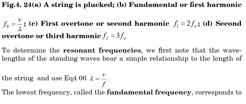
corresponds to one-half wavelength.
The other natural frequencies are called overtones; for a vibrating string
they are whole-number (integral) multiples of the fundamental, and then
are also called harmonics, with the fundamental being referred to as the
first harmonic. The next mode of vibration after the fundamental has two
loops and is called the second harmonic (or first overtone), Fig. 4.24c. The
length of the string at the second harmonic corresponds to one complete
A normal mode of an oscillating system is a motion in which all particles
of the system move sinusoidally with the same frequency
EXAMPLE 4
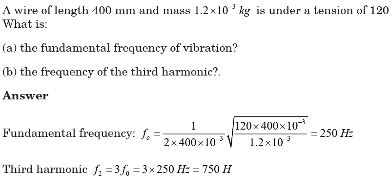
EXAMPLE 4
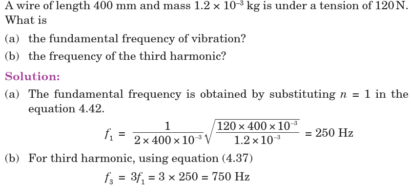
Application Activity 4.2
Use the following descriptions in waves and fill the puzzle
Down:
1) The part of a longitudinal wave where the particles of the medium
are close together.
2) A wave which needs to travel through a medium.
3) A repeated back-and-forth or up-and-down motion.
6) A wave which moves the medium in a direction across the direction.
the energy is traveling.
8) The ability to do work.
Across:
4) A disturbance that transfers energy from place to place.
5) The highest point of a wave.
7) The part of a longitudinal wave where the particles of the mediu
are far apart.
9) A wave which moves the medium in the same direction as the energy
is traveling.
10) The lowest part of a transverse wave.11) The material through which a wave travels.
END OF UNIT PROJECT
Materials to choose from:
3 white screens, 3 biconvex lenses, 3 biconcave lenses
mirrors
torches, 3 very bright open lamps, 1 plane mirror.
The question:
Explain how you can perform Fresnel’s diffraction and Fraunhofer
diffraction in the laboratory.
Hypothesis:
Write a hypothesis about how diffraction is obtained in the lab.
Procedure
1. Decide which materials you will need (from the list) to test the hypothesis.
2. Plan your investigation.
a. Which arrangements best gives the idea of diffraction?
b. Which adjustments do you care to take care of ?
3. Write a procedure and show it to your teacher. Do not proceed
any further until it is approved.
4. Carry out your investigation.
Collecting Data
Make sure you have recorded at least the following information:
◊ the hypothesis
◊ your procedure
Analyzing and Interpreting
Share and compare your results with your classmates. Which idea is
important to be used and achieve the proper arrangement of apparatus to
achieve your objective?
Forming Conclusions
Make a brief report of your project with neat diagrams. In this project whatis needed is the concept not the analysis of the fringes formed.
END OF UNIT ASSESSMENT
1. The string shown in Figure below is driven at a frequency of 5.00 Hz.
The amplitude of the motion is 12.0 cm, and the wave speed is 20.0 m/s.
Determine the angular frequency and wave number k for this wave, andwrite an expression for the wave function.
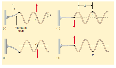
2. The wave shown in Fig. below is being sent out by a 60 Hz vibrator.
3. A string of length 3 m and mass density 0.0025 kg/m is fixed at both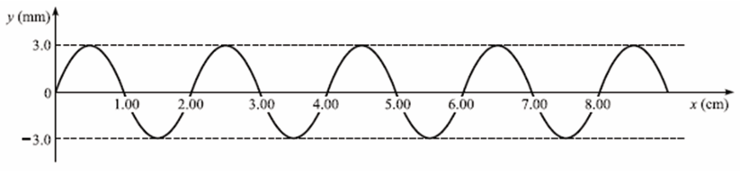
ends. One of its resonance frequencies is 252 Hz. The next higher res
onance frequency is 336 Hz. Find the fundamental frequency and the
tension in the string.
4. A wire of length 400 mm and mass 1.2 *10-3 kg is under a tension of 120
N. What is
a) the fundamental frequency of vibration?
b) the frequency of the third harmonic?
5. A sinusoidal wave traveling in the positive x direction has an amplitude
of 15.0 cm, a wavelength of 40.0 cm, and a frequency of 8.00 Hz. The
vertical position of an element of the medium at t = 0 and x = 0 is also15.0 cm, as shown in Figure below.
(A) Find the wave number k, period T, angular frequency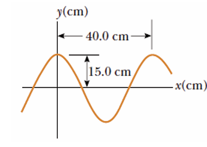
 and speed v of the wave.
(B) Determine the phase constant and write a general expression for the wave function.
UNIT SUMMARY
Waves can be defined as a disturbance in a material medium that transfers
energy from one place to another.
The time period (T) of the wave is the time it takes for one complete
vibration of the wave.
The frequency f is the number of wavelengths that pass a point in space
in one second.
The wavelength is the horizontal distance in space between two nearest
points that are oscillating in phase.
The wave speed v is the speed at which the wave advances.
Phase difference (phase angle) is the angular difference between two
points on the wave or between two waves.
The wave number also called the propagation number k is the spatial
frequency of a wave.
The Intensity of a wave or the power radiated by a source are proportional
to the square of the amplitude.
Wavefront is a line or surface in the path of the wave motion on which the
disturbance at every point have the same phase.
Mechanical waves are waves produced by the disturbance in a material
medium.
A progressive wave consists of a disturbance moving from one point to
another.
Longitudinal wave propagates through some medium with vibrations in
the direction of propagation of the disturbance.
In Transverse waves, the direction of vibrations is perpendicular to the
direction of propagation of the wave.Equation of a progressive wave is given by:
Principle of superposition states that the resultant displacement at any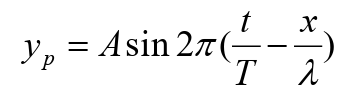
time is the vector sum of the individual displacements.Stationary waves are waves which seem to be at rest.
Electromagnetic waves are disturbances in form of varying electric and
magnetic fields.
All kinds of waves reflect, refract, interfere and also spread around the obstacle.
Other than the superposition of waves meeting at a point, other conditions
for interference are:
• The sources of the waves must be coherent, which means they emit
identical waves with a constant phase difference.
• The waves should be monochromatic - they should be of a singlewavelength.
UNIT 5: INTERFERENCE OF LIGHT WAVES
Key unit competence: Perform experiment for interference of light
waves.
Unit Objectives:
By the end of this unit I will be able to;
◊ explain the concept of wave interferences and their applications in our daily
life.◊ explain the interaction of electromagnetic radiations with the earth.
Introductory Activity
Observe the diagram below and answer the questions that follow
M,
a) Why do you think there are Minimum (min) and Maximum (Max)
regions as indicated on the screen?
b) Relating part a) and part b), what do you think lead to the formation
of the patterns as indicated in b)
c) What scientific phenomena, that explains the figure shown above?
d) Do you think the process indicated in the figure is applicable andimportant in the world we live in?
5.0. INTRODUCTION
Sun is a nuclear fireball spewing energy in all directions. The light that
we see it simply one part of the energy that the Sun makes that our eyes
can detect. When light travels between two places (from the Sun to the
Earth or from a flashlight to the sidewalk in front of you on a dark night),
energy makes a journey between those two points. The energy travels in the
form of waves (similar to the waves on the sea but about 100 million times
smaller)—a vibrating pattern of electricity and magnetism that we call
electromagnetic energy. If our eyes could see electricity and magnetism, we
might see each ray of light as a wave of electricity vibrating in one direction
and a wave of magnetism vibrating at right angles to it. These two waveswould travel in phase and at the speed of light.
5.1. NATURE OF ELECTROMAGNETIC WAVES
Electromagnetic waves are transverse waves that transfer electrical and
magnetic energy. An electromagnetic wave consists of vibrating electric
and magnetic fields that move through space at the speed of light. In other
words electromagnetic waves have electric and magnetic fields varyingperpendicularly as shown on Fig.5.1.
5.1.1 Producing electromagnetic waves
Electromagnetic waves are produced by charged particles and every charged
particle has an electric field surrounding it. The electric field produces
electric forces that can push or pull on other particles.
When a charged particle moves, it produces a magnetic field which exerts
magnetic forces that act on certain materials.
When this charged particle changes its motion, its magnetic field changes
and causes the electric field to change. When one field vibrates, so does the
other and the two fields constantly cause each other to change and this
produces an Electromagnetic wave.
Many properties of electromagnetic waves can be explained by a wave model
and some other properties are best explained by a particle model. Both a
wave model and a particle model are needed to explain all of the properties
of electromagnetic waves and in particular light.
5.1.2 Electromagnetic Radiation
Water waves transmit energy through space by the periodic oscillation of
matter (the water). In contrast, energy that is transmitted, or radiated,
through space in the form of periodic oscillations of electric and magnetic
fields is known as electromagnetic radiation. In a vacuum, all forms of
electromagnetic radiation—whether microwaves, visible light, or gamma
rays—travel at the speed of light (c), this is about a million times faster
than the speed of sound.
All forms of electromagnetic radiation consist of mutually perpendicular
oscillating electric and magnetic fields. Because the electromagnetic
radiations have same speed (c), they differ only in their wavelength andfrequency.
5.1.3 Electromagnetic spectrum
When you tune your radio, watch TV, send a text message, or pop popcorn
in a microwave oven, you are using electromagnetic energy. You depend on
this energy every hour of every day. Without it, the world you know would not exist.
Electromagnetic energy travels in waves and spans a broad spectrum from
very long radio waves to very short gamma rays. The human eye can only
detect only a small portion of this spectrum called visible light. A radio
detects a different portion of the spectrum, and an x-ray machine uses yetanother portion.
Generation, properties and uses of those waves are summarized in the table
below:
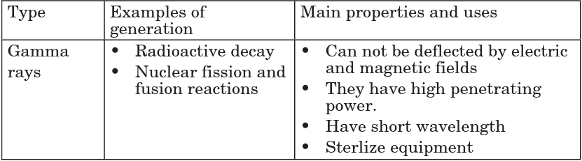
ACTIVITY 5-1: Spectrum of Electromagnetic Waves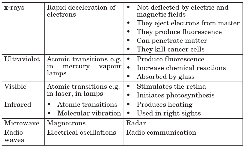
Aim: In this activity, you will investigate the spectrum of visible light
Materials needed: a white sheet of paper, a glass prism and colored
pencils
Shine a light through a prism so that the light leaving the prism falls
on an unlined piece of paper. What colours do you see? As you hold the
prism and light steady, your partner will use coloured pencils to draw
the colours on the piece of paper. Switch places with your partner. Again,
trace the colours you see onto the piece of paper.
◊ What colours do you see on the paper? What is the order of the colours?
◊ Is it difficult to see where one colour ends and the next begins?
◊ Did the order of the colours on the paper ever change?
◊ The term spectrummeans a range. How do you think this term is relatedto what you observed?
5.1.4 Radiation Interaction with the Earth
Radiation that is not absorbed or scattered in the atmosphere can reach
the earth and interact with its surface. There are three forms of interaction
that can take place when energy strikes, or is incident upon the surface.
These are: absorption (A); transmission (T); and reflection (R).
Reflection: Reflected light is perceived by our eye as colour, e.g. chlorophyll
in plants reflects green light. All colours of the visible spectrum are absorbed.
Absorption: The incident energy might not get reflected or transmitted but
is transformed into another form, such as heat or absorbed by chlorophyll
in the process of photosynthesis.
Transmission: When energy propagates through a medium, what is
not absorbed or reflected, will be transmitted through. For instance, an
ultraviolet filter on a camera absorbs UV rays but allows the remaining
energy to expose the film. Changes in density can also slow the velocity of
light resulting in refraction such as dispersion through a prism.
5.1.5 Radiation Interaction with the Atmosphere
The Earth’s atmosphere acts as a filter to remove radiations such as cosmic
rays, gamma rays, X-rays, UV rays, and large portions of the electromagnetic
spectrum through the process of absorption and scattering by gases, water
vapour, and particulate matter (dust).
Scattering occurs when particles or large gas molecules present in the
atmosphere cause the electromagnetic radiation to be redirected from its
original path. There are three types of scattering which take place: Rayleigh
Scattering, Mie Scattering, Non-selective Scatter.
Rayleigh scattering refers to the scattering of light off by the molecules of
air. It can be extended to scattering from particles of sizes up to about one
tenth of the wavelength of the light. It is Rayleigh scattering of white lightby the molecules of the air which gives us the blue sky.
Mie scattering is caused by pollen, dust, smoke, water droplets and other
particles in the lower portion of the atmosphere. It occurs when the particles
causing the scattering are larger than the wavelengths of radiation in
contact with them. Mie scattering is responsible for the white appearanceof the clouds, as seen below.
Non-Selective Scattering occurs when the particles are much larger than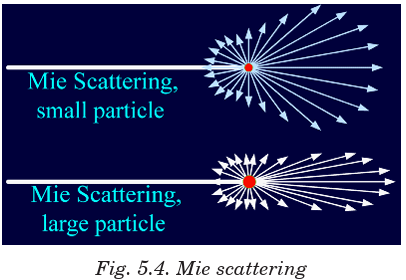
the wavelength of the radiation. Water droplets and large dust particles can
cause this type of scattering and cause fog and clouds to appear white to our
eyes because blue, green, and red light are all scattered in approximately
equal quantities (blue+green+red light = white light).
5.1.6 Atmospheric Absorption of electromagnetic waves
In addition to the scattering of EM radiation, the atmosphere also absorbs
electromagnetic radiation. The three main constituents of atmosphere
which absorb parts of solar radiation are Ozone, Carbon dioxide, and Water
Vapour.
Ozone serves to absorb the harmful ultraviolet radiations from the sun.
Without this protective layer in the atmosphere, our skin would burn whenexposed to sunlight. Ultraviolet rays can also cause skin cancer to people.
Carbon Dioxide absorbs the far infrared portion of the spectrum which is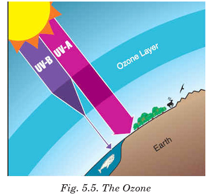
related to thermal heating and results in a ‘greenhouse’ effect.
Water Vapour absorbs energy depending upon its location and concentration,and forms a primary component of the Earth’s climatic system.
5.2. CONDITIONS FOR INTERFERENCE WITH TWO
SOURCES OF LIGHT
When two waves of exactly same frequency (coming from two coherent
sources) travel in a medium, in the same direction simultaneously then due
to their superposition, at some points intensity of light is maximum while
at some other points intensity is minimum. This phenomenon is called
Interference of light.
There are two types of interference: constructive interference and
destructive interference.
A constructive interference is produced at a point when the amplitude of
the resultant wave is greater than that of any individual wave.
A destructive interference is produced at a point when the amplitude of the
resultant wave is smaller than that of any individual wave.
Conditions for interference
When waves come together they can interfere constructively or destructively.
To set up a stable and clear interference pattern, two conditions must be met:
• The sources of the waves must be coherent, which means they emit
identical waves with a constant phase difference.
• The waves should be monochromatic - they should be of a singlewavelength.
5.3. PRINCIPLE OF SUPERPOSITION
The principle states that when two or more than two waves superimpose
over each other at a common particle of the medium then the resultantdisplacement
of the particle is equal to the vector sum of the displacements

Consider two waves given as:
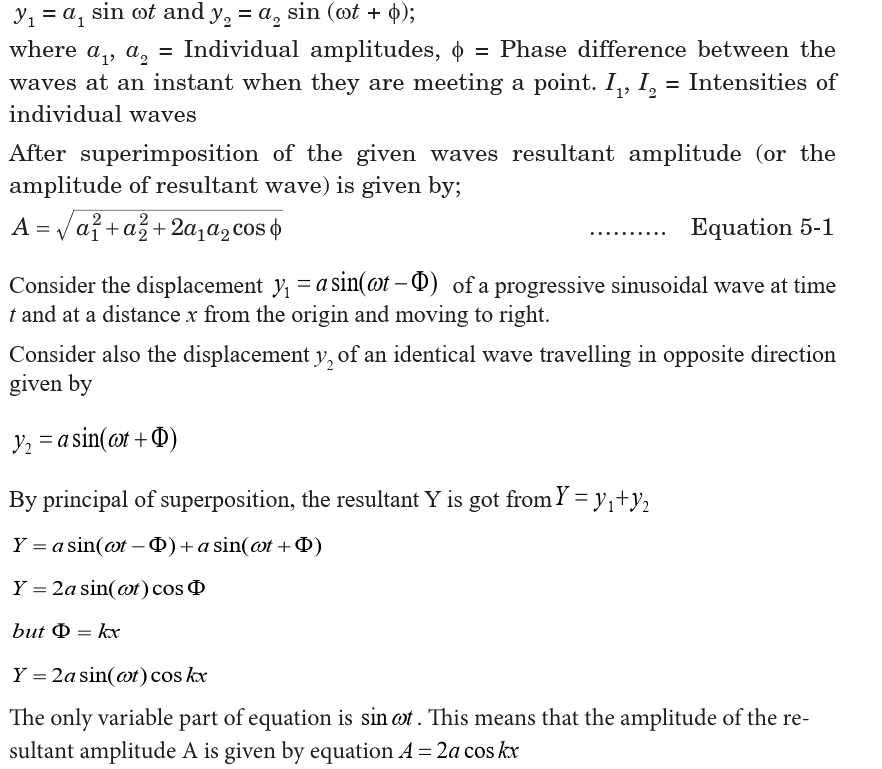
EXAMPLES
1. Two waves traveling in opposite directions produce
a standing wave. The individual wave functions are
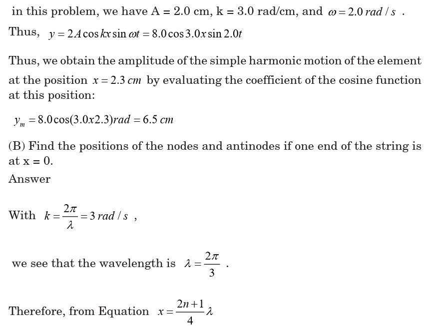
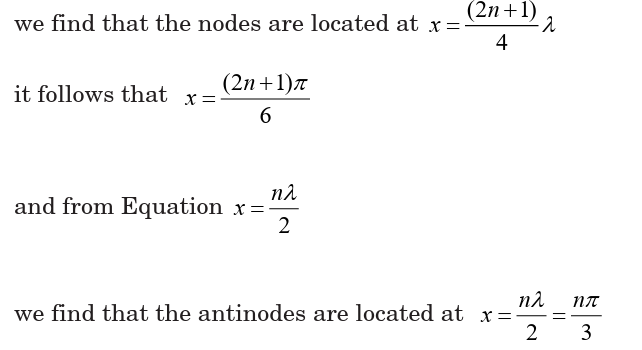
(C) What is the maximum value of the position in the simple harmonic
motion of an element located at an antinode?
Answer
The maximum position of an element at an antinode is the amplitude ofthe standing wave, which is twice the amplitude of the individual traveling waves:

where we have used the fact that the maximum value of
5.4. INTERFERENCE PATTERN OF TWO COHERENT
POINT SOURCES OF LIGHT
The sources of light which emit continuous light waves of the same
wavelength, same frequency and are in same phase (or have a constant
phase difference) are called coherent sources. Two coherent sources areproduced from a single source of light by using Young’s double slits.
From the Fig. 13.7. S1 and S2 are coherent sources and show interference
as light passes through two slits. It also shows the appearance of the
interference pattern on a screen placed in the path of the beam. You can
see the maxima and minima and the way in which the intensity changes.
Changing the wavelength of the light, the separation of the slits or the
distance of the slits from the screen will all give changes in the separation
of the maxima in the interference pattern.
5.5. YOUNG'S DOUBLE-SLIT EXPERIMENT
Monochromatic light (single wavelength) falls on two narrow slits S1
and S2 which are very close together and act as two coherent sources.
When waves coming from two coherent sources superimpose on each other,an interference pattern is obtained on the screen. In Young’s double slit
experiment alternate bright and dark bands are obtained on the screen.These bands are called Fringes.
Following points must be noted and observed in the above experiment: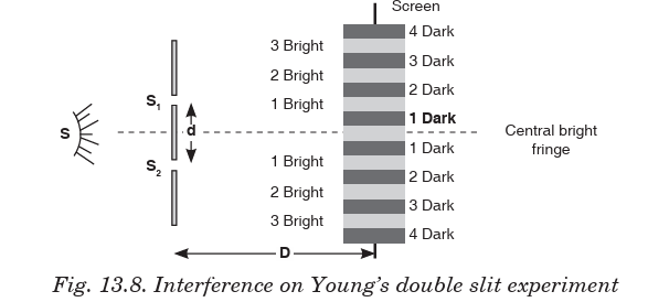
• Central fringe is always bright, because at central position,
the path difference
• The fringe pattern obtained due to a slit is more bright than that due
to a point.
• If the slit widths are unequal, the minima will not be completly dark.
For very large slit width, uniform illumination occurs, i.e. bright and
dark fringes are not formed.
• If one slit is illuminated with red light and the other slit is illuminated
with blue light, no interference pattern is observed on the screen.
• If the two coherent sources consist of object and its reflected image,
the central fringe is dark instead of bright one.
Calculation of fringe separation/fringe width
Consider two coherent sources (slits) S1 and S2
separated by distance d.
The distance D from the plane of slits to the screen is much greater than d.
Consider a wave from S1 that meets another wave from S2 at point P.
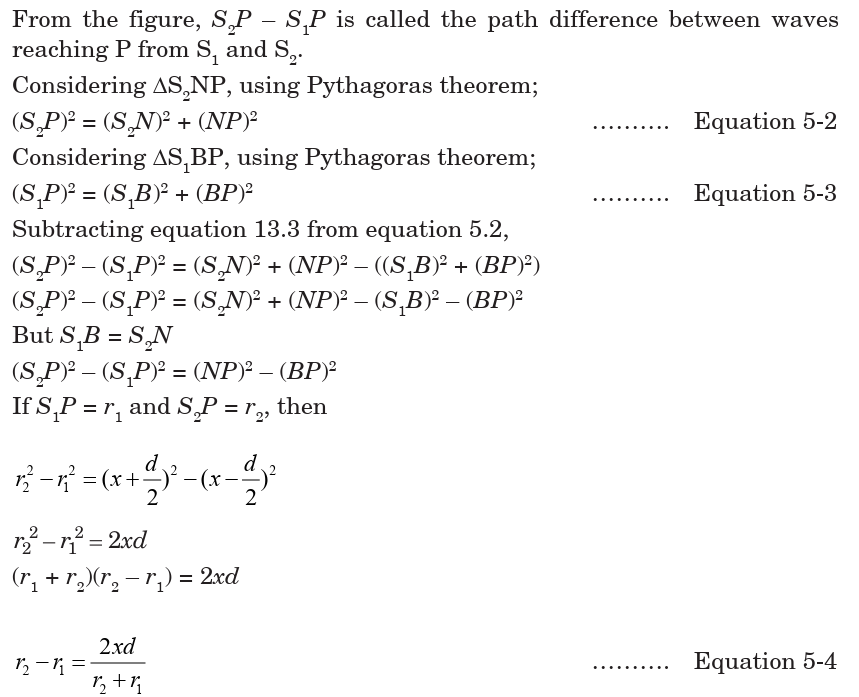
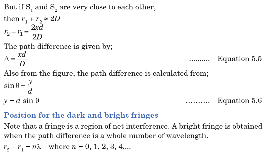
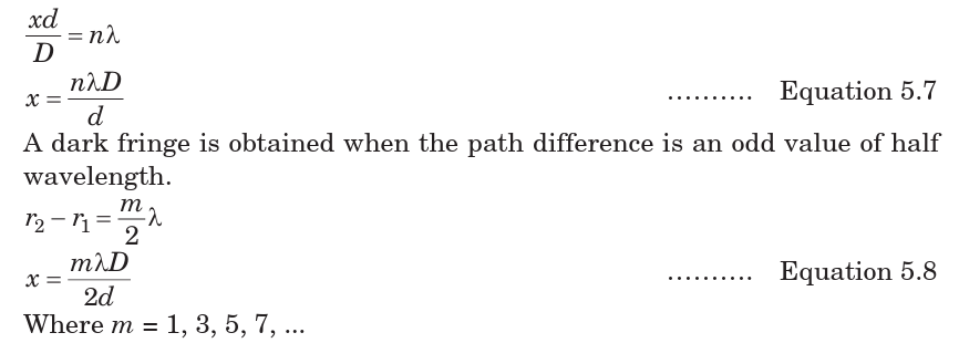
Example
1. A viewing screen is separated from a double-slit source by 1.2 m. The distance
between the two slits is 0.030 mm. The second-order bright fringe (m = 2) is 4.5 cm
from the center line.
(a) Determine the wavelength of the light.
(b) Calculate the distance between adjacent bright fringes.Solution
• Increasing the width of the slits increases the intensity of waves and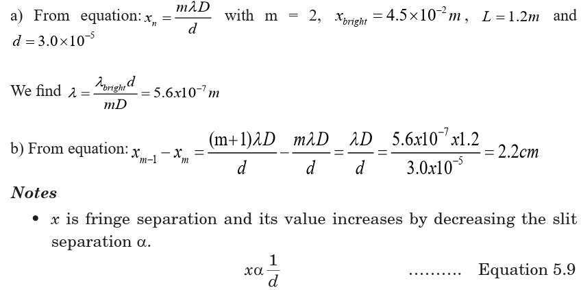
fringes become more blurred.
Application Activity 5.2
1. What is the necessary condition on the path length difference between
two waves that interfere (a) constructively and (b) destructively?
2. If Young’s double-slit experiment were performed under water, how
would the observed interference pattern be affected?
3. In Young’s double-slit experiment, why do we use monochromatic
light? If white light is used, how would the pattern change?
4. The distance between the two slits is 0.030 mm. the second-order
bright fringe (m = 2) is measured on a viewing screen at an angle of
2.150 from the central maximum. Determine the wavelength of the light.
5. A 2-slit experiment is set up in which the slits are 0.03 m apart.
A bright fringe is observed at an angle 10° from the normal. What is
wavelength of electromagnetic radiation being used?
6. In Young’s double slit experiment the separation between the 1st and
5th bright fringes is . When the wavelength used is
The distance from the slits to screen is 0.8 m. Calculate the separationof the slits
5.6. INTENSITY DISTRIBUTION OF FRINGE PATTERN
So far we have discussed the locations of only the centers of the bright and
dark fringes on a distant screen. We now direct our attention to the intensity
of the light at other points between the positions of maximum constructive and
destructive interference. In other words, we now calculate the distribution oflight intensity associated with the double-slit interference pattern.
Again, suppose that the two slits represent coherent sources of sinusoidal
waves such that the two waves from the slits have the same angular
frequency w and a constant phase difference . The total magnitude of
the electric field at point P on the screen is the vector superposition of the
two waves. Assuming that the two waves have the same amplitude E0, we
can write the magnitude of the electric field at point P due to each waveseparately as;
Finally, to obtain an expression for the light intensity at point P, the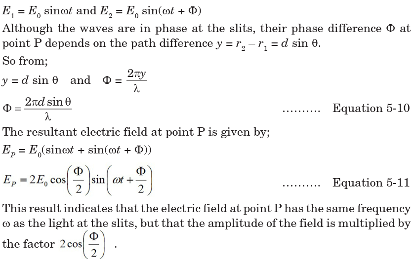
intensity of a wave is proportional to the square of the resultant electricfield magnitude at that point;

Note that the interference pattern consists of equally spaced fringes of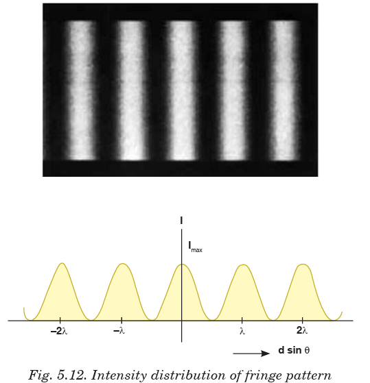
equal intensity. Remember, however, that this result is valid only if theslit-to-screen distance D is much greater than the slit separation d.
Application Activity 5.3
1. In a double slit interference experiment, the distance between the
two slits is 0.0005m and the screen is 2 m from the slits. Yellow
light from a sodium lamp is used and it has a wavelength of 5.89 ×
10-7 m. Show that the distance between the first and second fringes
on the screen is 0.00233 m.
2. With two slits are spaced 0.2 mm apart, and a screen at a distance of
D = 1 m, the third bright fringe is found to be displaced h = 7.5mm from
the central fringe. Show that the wavelength, , of the light used is
5 × 10⁻⁷ m.
3. Two radio towers are broadcasting on the same frequency. The
signal is strong at A, and B is the first signal minimum. If d = 6.8 km,
L = 11.2 km, and y = 1.73 km, what is the wavelength of the radiowaves to the nearest meter?
4. Water waves of wavelength of 5.44 m are incident upon a breakwater
with two narrow openings separated by a distance 247 m. To the
nearest thousandth of a degree, what is angle corresponding to thefirst wave fringe maximum?
UNIT SUMMARY
Nature of electromagnetic waves
Electromagnetic waves are transverse waves that transfer electrical and
magnetic energy.
In other words electromagnetic waves have electric and magnetic fields
varying perpendicularly.
Producing electromagnetic waves
Electromagnetic waves are produced by charged particles and every charged
particle has an electric field surrounding it. The electric field produceselectric forces that can push or pull other particles.
Electromagnetic Radiation
All forms of electromagnetic radiation consist of perpendicularly oscillating
electric and magnetic fields. Various kinds of electromagnetic radiations
have the same speed (c). They differ only in wavelength and frequency.
Electromagnetic energy travels in waves and spans a broad spectrum
from very long radio waves to very short gamma rays. This is called
electromagnetic spectrum.
From memory you should be able to list the parts in order of energy (relate
how that relates to frequency and wavelength) and know how they are
produced, detected and their dangers and uses - a rough idea of their
approximate wavelength is also useful!
Radiation Interaction with the Earth
Radiation that is not absorbed or scattered in the atmosphere can reach
and interact with the Earth’s surface. There are three forms of interaction
that can take place when energy strikes, or is incident upon the surface.
These are: absorption (A), transmission (T) and reflection (R).
Radiation Interaction with the Atmosphere
The Earth’s atmosphere acts as a filter to remove radiation such as cosmic
rays, gamma rays, X-rays, UV rays and large portions of the electromagnetic
spectrum through the process of absorption and scattering by gases, water
vapour and particulate matter (dust).
Atmospheric Absorption of electromagnetic waves
In addition to the scattering of EM radiation, the atmosphere also absorbs
electromagnetic radiation. The three main constituents which absorb
radiation are Ozone, Carbon Dioxide and Water Vapour.
Conditions for interference to occur
• The sources of the waves must be coherent, which means they emit
identical waves with a constant phase difference.
• The waves should be monochromatic - they should be of a single
wavelength.
Principle of superposition
The principle states that when two or more than two waves superimpose
over each other at a common particle of the medium then the resultantdisplacement (y) of the particle is equal to the vector sum of the displacements
Double-slit experiment
Monochromatic light (single wavelength) falls on two narrow slits S1
and S2 which are very close together acts as two coherent sources, when
waves coming from two coherent sources superimposes on each other, an
interference pattern is obtained on the screen
A bright fringe is obtained when the path difference is a whole number ofwavelength.
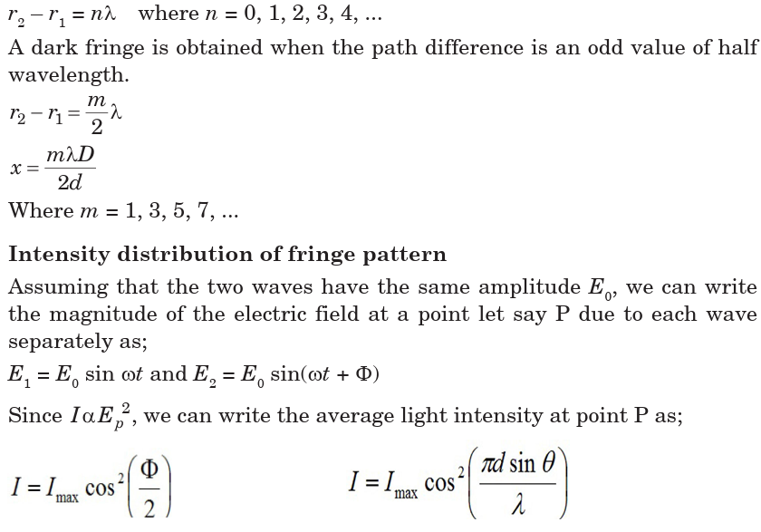
UNIT 6:COMPLEX ELECTRICAL CIRCUIT
Key topic competence: By the end of the unit I should be able to
construct and to analyze a complex electrical circuit.
Unit Objectives:
By the end of this unit, I should be able to:
◊ analyse complex electrical circuits well.
◊ use Kirchhoff’s laws in circuit analysis accurately◊ analyse simple potentiometer circuits clearly.
Introductory Activity
Look at the illustration given above.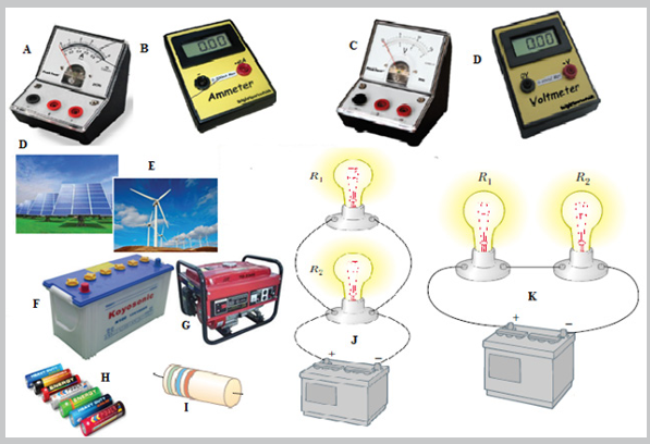
a. What type of devices available in the illustration above?
b. Can you suggest the names of the available devices in the
illustration above?
c. Is there any complete circuit in the illustration above?
d. What kind of electrical circuits identified in the illustration above?
e. Have you ever used or connected these electrical components
somewhere? If yes, what were the difficulties in handling these
electrical components in circuit construction?
f. What can be considered to select the best electrical device(s) to
be used in electrical circuit construction?
g. What can be put in recognition to minimize risks when
connecting these electrical components in the circuit?
6.0 INTRODUCTION
A complex circuit configuration is one that contains components that are
connected either in parallel or in series with each other. If a circuit can
be reduced to a single resistor, it is a series or parallel circuit. If not, it is
a complex circuit. If the circuit is complex and is mixed with series and
parallel networks of resistors and supplies, we may want to look if it is
feasible to reduce these to a single power supply and a single resistor which
would make them either a series or a parallel simple circuit.
Most electronic devices we use at home have built-in complex circuits to
perform different tasks. Also the concept of this unit is helpful in other
subjects like electrons and conductors (in Chemistry), volume adjustment
circuits in radios.
Opening questions
1. A combination circuit is shown in the diagram of Fig.5.1. Use the
diagram to answer the following questions.
a. The current at location A is _____ (greater than, equal to, less than)
the current at location B.
b. The current at location B is _____ (greater than, equal to, less than)
the current at location E.
c. The current at location G is _____ (greater than, equal to, less than)
the current at location F.
d. The current at location E is _____ (greater than, equal to, less than)
the current at location G.
e. The current at location B is _____ (greater than, equal to, less than)
the current at location F.
f. The current at location A is _____ (greater than, equal to, less than)
the current at location L.
g. The current at location H is _____ (greater than, equal to, less than)
the current at location I.
2. Consider the combination circuit in the diagram of Fig.5.1. Use the
diagram to answer the following questions. (Assume that the voltage
drop in the wires is negligibly small.)
a. The electric potential difference (voltage drop) between points
B and C is _____ (greater than, equal to, less than) the electric
potential difference (voltage drop) between points J and K.
b. The electric potential difference (voltage drop) between points
B and K is _____ (greater than, equal to, less than) the electric
potential difference (voltage drop) between points D and I.
c. The electric potential difference (voltage drop) between points E and
F is _____ (greater than, equal to, less than) the electric potential
difference (voltage drop) between points G and H.
d. The electric potential difference (voltage drop) between points E and
F is _____ (greater than, equal to, less than) the electric potential
difference (voltage drop) between points D and I.
e. The electric potential difference (voltage drop) between points J and
K is _____ (greater than, equal to, less than) the electric potential
difference (voltage drop) between points D and I.
f. The electric potential difference between points L and A is _____
(greater than, equal to, less than) the electric potential difference(voltage drop) between points B and K.
6.1 KIRCHHOFF’S LAWS
Next to Ohm’s Law in the fundamental rules which govern the behaviour
of electric circuits are Kirchhoff’s Circuit Laws. Gustav Kirchhoff in
1845 formulated two circuit laws, one of which essentially establishes
the conservation of charge and the other establishes the conservation ofpotential.
ACTIVITY 6-1
The 16 puzzle pieces associated with this problem represent different
circuit elements. Arrange the circuit pieces to form a four-by-four-piece
square, with the “sun” symbol appearing somewhere within the puzzle.
If all of the puzzle pieces are placed appropriately, the sun will be in aspecific position.
6.1.1 Kirchhoff’s Current Law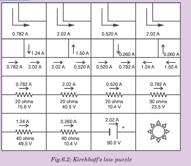
Kirchhoff’s first law, known as Kirchhoff’s Current Law (KCL) or Kirchhoff’s
Junction Rule, essentially expresses the conservation of charge, which can
be thought of as the conservation of matter. This implies that charge cannot
appear from anything at any point in a circuit, neither can it disappear into
oblivion at any point.
Kirchhoff’s Current Law states that “the algebraic sum of the currents
flowing at a node or junction in an electric circuit is zero”.
This means that currents are added with respect to their directions. Let usconsider the junction shown on Fig. 6.3 below.

Notes: Any calculated value of current which works out to be negative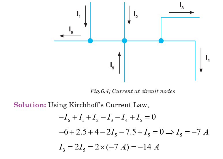
simply indicates that in practice, the current is actually flowing in adirection opposite to that assigned in the schematic diagram of the circuit.
6.1.2 Kirchhoff’s Voltage Law
Kirchhoff’s second circuit law, known as Kirchhoff’s Voltage Law (KVL) or
Kirchhoff’s Loop Rule, essentially formulates the conservation of energy in
the form of electric potential around a circuit in which current is flowing.
This means that no net voltage can be created or destroyed around the loop
of a closed circuit.
Kirchhoff’s Voltage Law states that “the algebraic sum of the potentials
around a closed electric circuit is zero.”Consider an electrical network shown in Fig. 6.5 below.
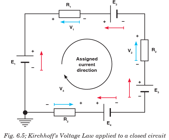
Kirchhoff’s Voltage Law gives:

Sign conventions
• The potential change across a resistor is – IR if the loop is traversed
along the chosen direction of current (potential drops across a resistor).
• The potential change across a resistor is + IR if the loop is traversed
opposite the chosen direction of current.
• If an emf source is traversed in the direction of the emf, the change in
potential is positive.
• If an emf source is traversed in the opposite direction of the emf, thechange in potential is negative.
6.2 DESIGN OF COMPLEX AND SIMPLE ELECTRIC CIRCUITS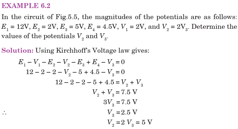
An electric circuit is a collection of electrical components connected by
conductors. A simple electric circuit consists of a supply with either seriesor parallel network of resistors.
This circuit contains neither simple series nor simple parallel connections.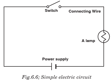
It contains elements of both. It is complex circuit because the circuit is
a combination of both series and parallel, we cannot apply the rules for
voltage, current and resistance “across the table” to begin its analysis. Thisis shown below;
ACTIVITY 6-2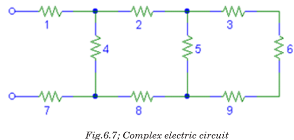
A. A circuit with two or more
braches for the current to flow
B. A material that electrons can
move through
C. Flow of electrons through a
conductor
D. Made up of series and parallel
circuits
E. Device to break a circuit
F. Poor conductor of electricity
G. Unit for measuring rate of
electron flow in a circuit
H. Having too many or too few
electrons
I. A temporary source of electric
current
J. Rate at which a device converts
electrical energy to another form of
energy.
1. Electric charge
2. Insulator
3. Conductor
4. Electroscope
5. Electric current
6. Resistance
7. Battery
8. Circuit
9. Series circuit
10. Parallel circuit
11. Complex circuit
12. Volt
13. Ampere
14. Switch15. Power
K. Path of electric conductors
L. Electric charge built up in one place
M. Device that detects electric charges
N. Opposition to the flow of electricity
O. Electric circuit where current
flows through all parts of the circuitP. Unit to measure electric potential
Aim: to know different components of the circuit and why they are needed
in the circuit.Instructions: match the following terms are used in electric circuits
ACTIVITY 6-3
For each of the following circuits state if it is series, parallel or
complex if any. In each case comment on the current flowing and thebrightness of the bulb.
6.3 RESISTORS AND ELECTROMOTIVE FORCES IN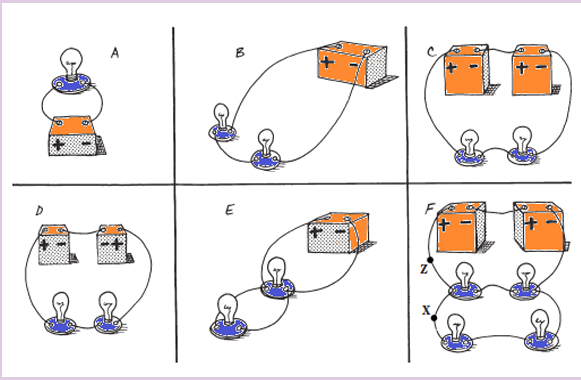
SERIES AND PARALLEL COMPLEX CIRCUITS
This section examines how Kirchhoff’s voltage and current laws are applied
to the analysis of complex circuits. In the analysis of such series-parallel
circuits, we often simplify the given circuit to enable us to clearly see how
the rules and laws of circuit analysis apply. We might need to redraw
circuits whenever the solution of a problem is not immediately apparent.
Resistors are said to be in series if they are arranged side by side in a
such way that the total potential difference is shared by all resistors and
the current flowing through them is the same. This arrangement is shownbelow:
A parallel circuit is a circuit in which the resistors are arranged with their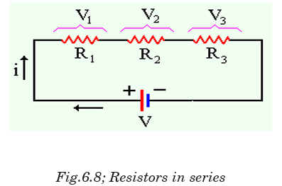
heads connected together, and their tails connected together. The current
in a parallel circuit breaks up, with some flowing along each parallel branch
and re-combining when the branches meet again. The voltage across eachresistor in parallel is the same.
The same idea of series and parallel resistors is applied in series and parallel
cells. For series e.m.fs the total e.m.f is equivalent to the sum of individuale.m.fs with respect to the direction of currents they generate.
When these cells are connected in parallel, the total e.m.f e equivalent to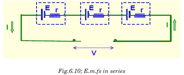
the e.m.f of only one cell.
To solve the resistor circuits using Kirchhoff’s rules,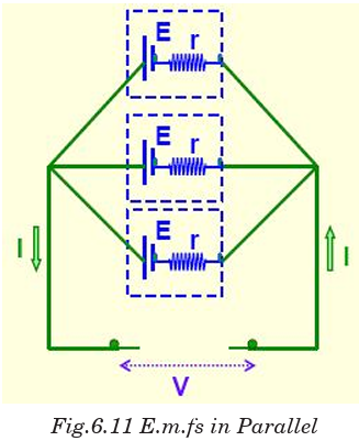
1. Define the various currents
• This can be done by either defining branch (segment) currents for
each element in the circuit, or defining loop currents for each loop in the circuit.
2. If using branch currents, use Kirchhoff’s Junction Rule to look for
interdependent currents. This allows for reducing the number of
variables being solved for.
3. Use Loop Rule to define voltage equations for each loop, using previously
defined currents.4. Solve set of simultaneous equations using algebraic manipulation.
EXAMPLE 6.3
Using Kirchhoff’s rules, calculate the currents I1
, I2 and I3 in the three branches of the circuit in Fig.5.12.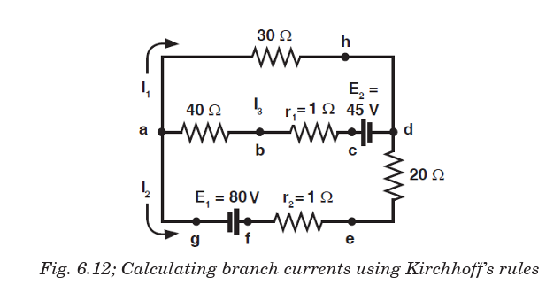
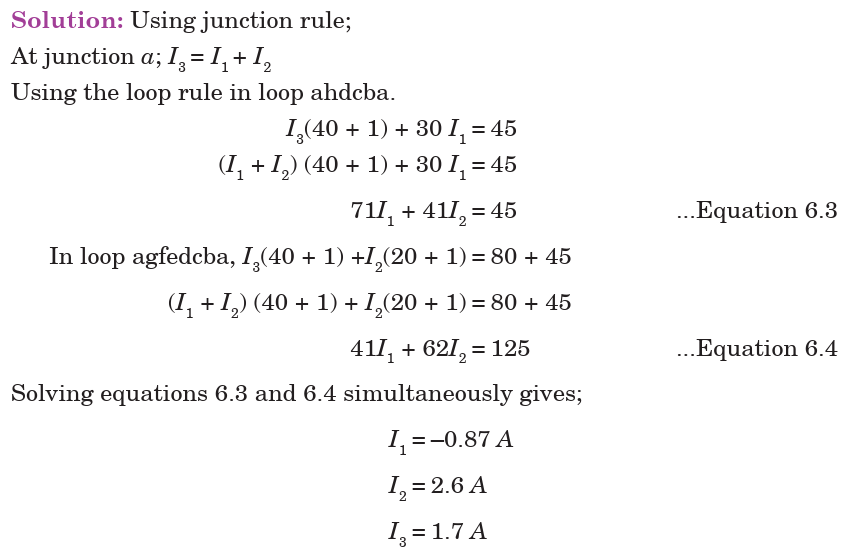
Ammeter
An ammeter is a device which is used to measure electric current flowing
through a branch of a circuit. Electric current is measured in amperes (A).
Smaller currents are measured by milliammeters (mA) and microammeters . Ammeters are of various types–moving coil ammeter, moving magnet
ammeter, moving iron ammeter, hot wire ammeter, etc. Nowadays, digital
ammeters are used to measure current accurately which use ADC (analog
to digital converter). An ammeter is connected in series with the circuitthrough which current is flowing.
Voltmeter
A voltmeter is a device which is used to measure electric potential difference
between two points in an electrical circuit. Electric p.d. is measured in
along a calibrated scale in proportion to circuit voltage. Digital voltmeters
are now frequently used to give a display of voltage using ADC. A voltmeter
is always connected in parallel to the component across which p.d. is to bemeasured.
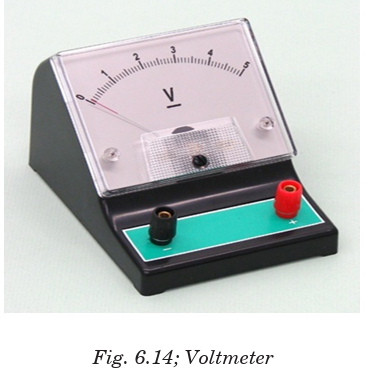
6.4 SIMPLE POTENTIOMETER CIRCUITS
A simple potentiometer is a device used for taking a number of electrical
measurements. It is a piece of resistance wire, usually a metre long, fixed
between two points A and B with a cell of output voltage, V, connected
between the two ends. The potential difference to be measured is put intoa circuit together with an opposing variable p.d. from the voltage divider.
The voltage divider is then adjusted until its p.d., VAC equals the p.d. beingmeasured. Fig. 6.15 illustrates this.
The sliding contact in the above diagram is moved until the galvanometer
indicates zero. This position is referred to as the balance p oint. The current
in the lower part of the circuit is zero because the p.d., VAC equals the p.d.
E provided by the cell under test. The protective resistor serves only to
prevent the galvanometer from the damage.
Electromotive force of the wire is always proportional to the length of thewire. So, the approximate value of E is determined as follows:

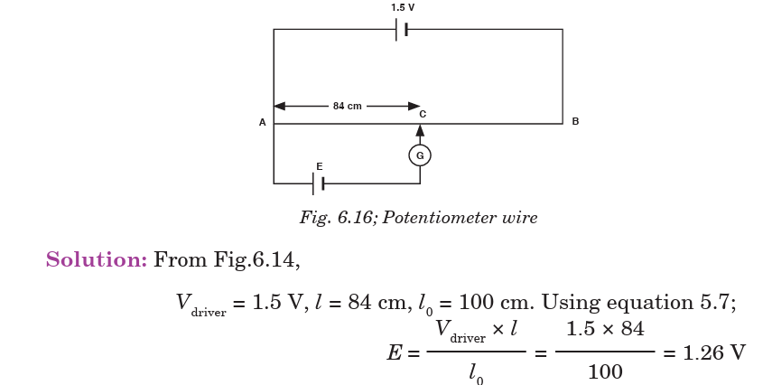
EXAMPLE 6.5
What value of resistance is needed in series with a driver cell of negligible
Solution: At the balance point or null point, no current flows through the
galvanometer, i.e. in the lower loop of the circuit. But in the lower loop ofthe circuit, a current I flows. Since the current in the lower loop is zero.

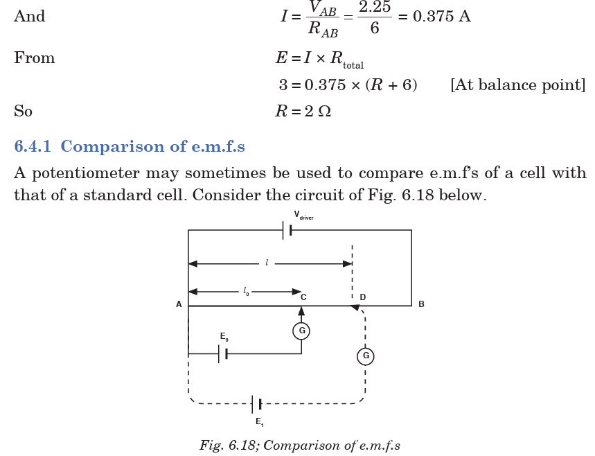
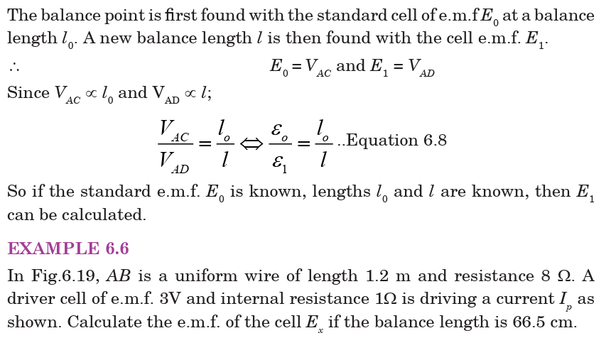
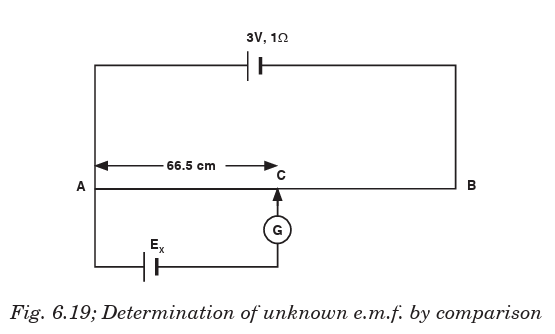
6.4.2 Measurement of internal resistance of a cell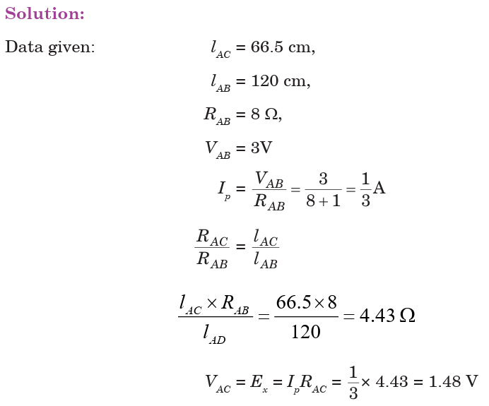
The circuit is arranged as shown in Fig. 6.20 with the cell, whose internal
resistance r is to be found, is connected in parallel with a resistor with
resistance R and a switch. The driver cell as usual is in the upper loop ofthe circuit.
The balance point l is found with the switch open. Since at balance point, no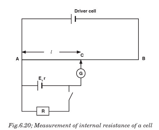
current is flowing through G; E is then measured. The switch is then closed
and the new balance point l1 is found. Balance length l1 is proportional tooutput voltage V (across the resistor R); i.e.
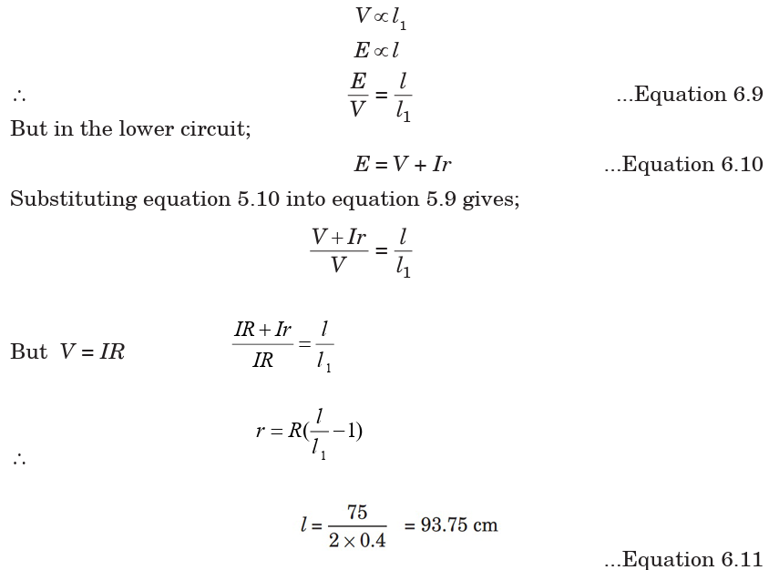
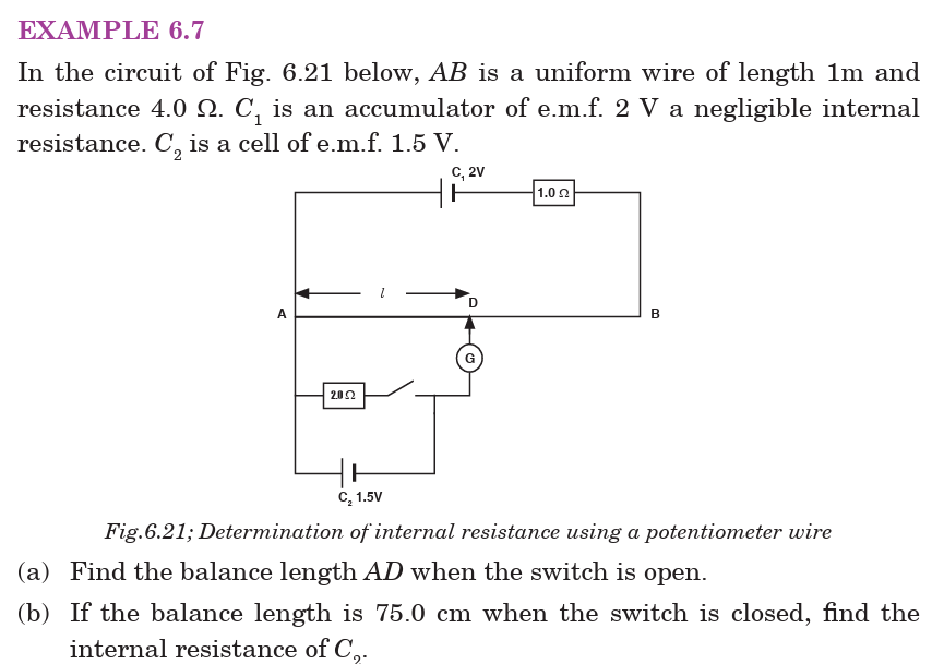

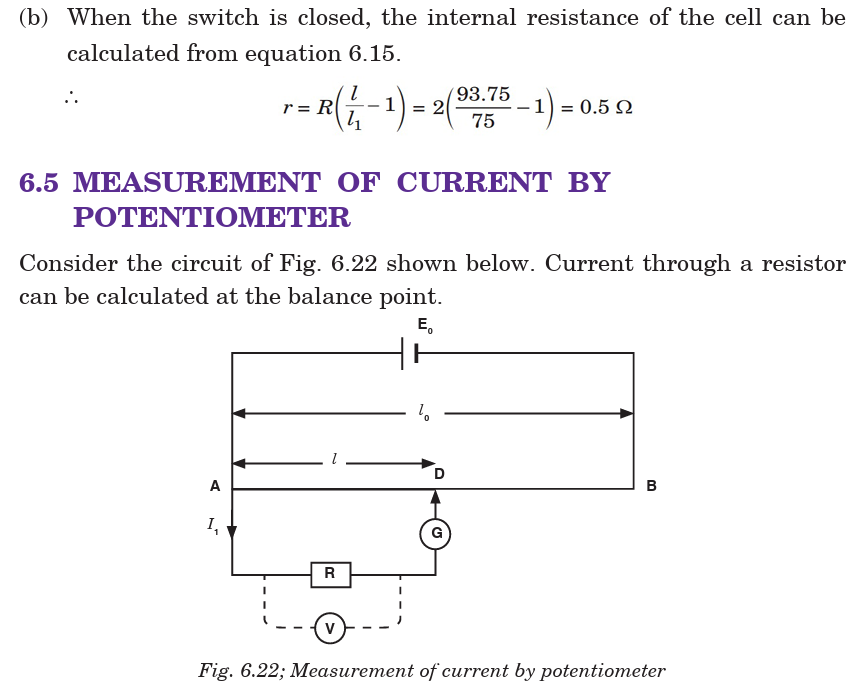
ACTIVITY 6-4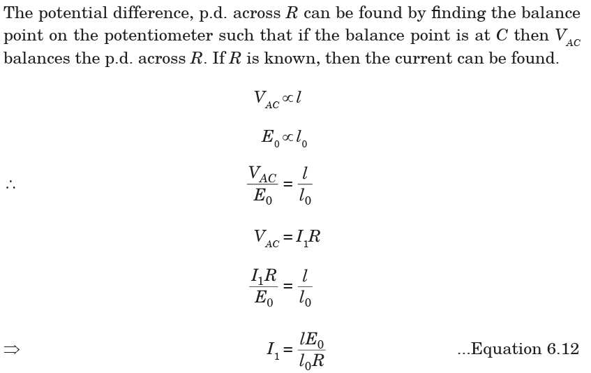
To measure the e.m.f. of an unknown cell using a potentiometer.
Procedure:
(a) Connect the circuit as shown in Fig. 6.23. Voltage supply is set at its
appropriate value, so the current is fairly small. This is to protect
the galvanometer.
(b) Close the DPDT (Double Pole Double Throw) switch to the standard
cell side and calibrate the potentiometer by finding what length of
wire corresponds to the voltage of the standard cell. This is done by
finding the location of the sliding contact where the galvanometer
does not deflect when the key switch is closed.
(c) Calculate the constant, k, using the e.m.f. of the standard cell and
the length, LS
measured to the sliding contact-use equation E = kLs
(d) Throw the DPDT switch to connect the unknown battery in the
circuit and move the sliding contact until the galvanometer indicates
zero current as in Step 2. (Do not adjust Rheostat Rt since this will
change the voltage across the potentiometer wire and upset your
calibration). Read the length Lv
measured on the sliding contact.
(e) Calculate the e.m.f. of the unknown battery by the formula: E = kLv
(f) Now measure the voltage of the unknown battery with the voltmeter.Explain the difference.
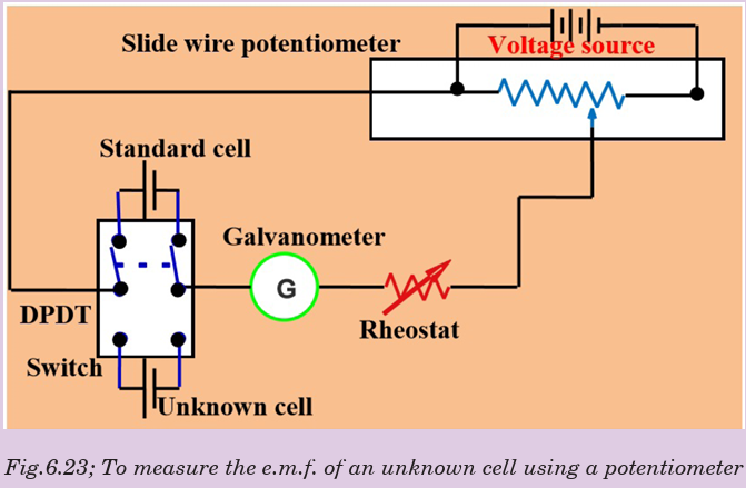
ACTIVITY 6-5
Determination of the constant of the wire.
Procedure:(a) Fix the wire provided firmly on the bench.
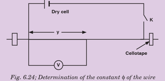
Application Activity 6.1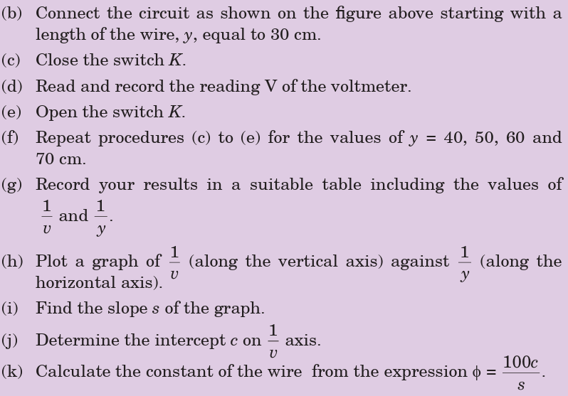
1. A potentiometer is set up as shown in Fig. 6.25. Given that the
balancing point for the unknown e.m.f. E is found to be 74.5 cm
from the left hand end of the meter wire (1 m). If the driver cell has
an e.m.f. of 1.5 V and negligible internal resistance. Find the valueunknown e.m.f.
2. A certain cell is connected to a potentiometer and a balance point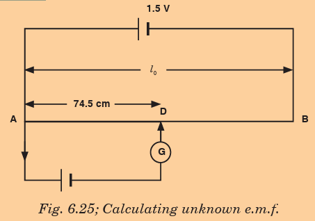
is obtained at 84 cm along the meter wire. When its terminals are
connected to a 5 resistor, the balance point changes to 70 cm.
Calculate the balance when a 5 resistor is now replaced by a 4
resistor.
6.6 ADVANTAGES AND DISADVANTAGES OF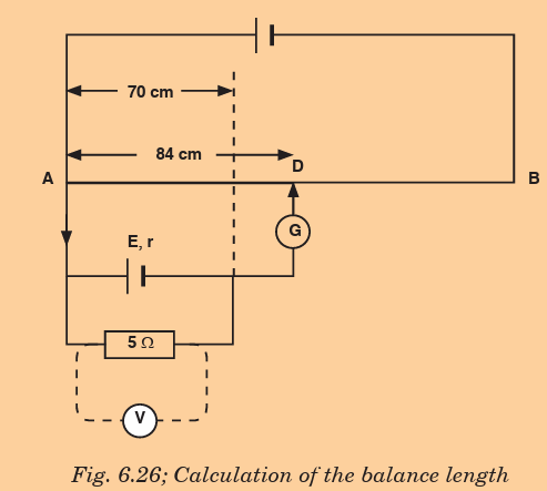
POTENTIOMETER
Wear: Most potentiometers last only a few thousand rotations before the
materials wear out. Although it means years of service in some applications,
it takes special designs to stand up to daily, demanding use. It means they
can’t be used for machine sensing where rapid cycling would wear them out
in a matter of minutes.
Noise: The action of the wiper moving across the element creates a noise
called “fader scratch.” In new pots, this noise is inaudible, but it can get
worse with age. Dust and wear increase the bumpiness of the action and
make the noise noticeable. Small cracks can appear in the element, and
these make noise as the wiper moves over them.
In addition to these mechanically caused noises, carbon elements, in
particular, are prone to producing electrical noise. This noise is heard as a
soft, steady hiss that can degrade sound recordings. The resistive materials
have improved over the years, so newer pots are quieter.
Inertia: The friction between the potentiometer’s wiper and resistive
element creates a drag or inertia that the pot must overcome before it
turns. Although this drag is not large, it prevents the pot from being used
as a rotary sensor in more sensitive applications.
Limited Power: Out of necessity, most potentiometers can dissipate only a
few watts of power. To handle more power, they have to be larger and hence
expensive. Engineers work around this problem by putting the potentiometer
in low-power parts of circuits. They control small currents, which, in turn,control transistors and other components with greater power ratings.
END OF UNIT ASSESSMENT
1. What are Kirchhoff’s rules for understanding a circuit?
2. Explain why Kirchhoff’s junction rule must be true if the Law of
Conservation of Charge (that no charge may be created or destroyed) is true.
3. Explain why Kirchhoff’s loop rule must be true if the Law of Conservation
of Energy is true.4. Find the branch currents of the circuit shown below.
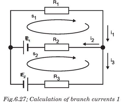

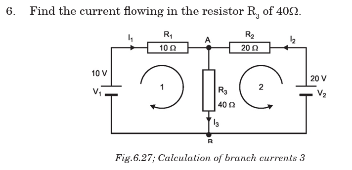


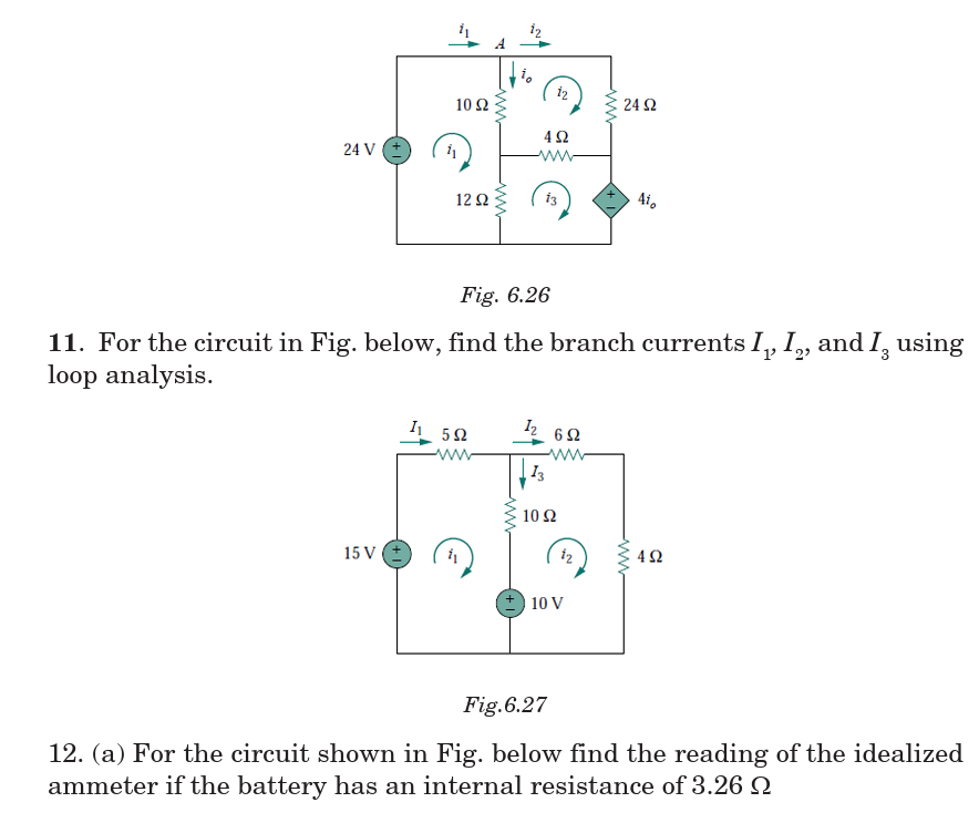
(b) Solve the equations to find the current through each resistor in the circuit.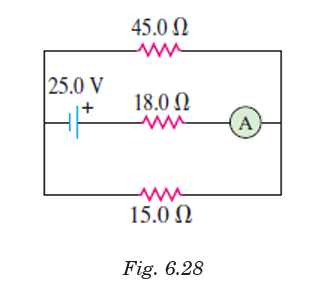
13. (a) Apply Kirchhoff’s rules to the following circuit to find a set ofequations that describe how charges behave inside the circuit
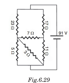
(b) Solve the equations to find the current through each resistor in the circuit.
UNIT SUMMARY
Kirchhoff’s laws
There are two Kirchhoff’s laws: Kirchhoff’s Current Law states that “the
algebraic sum of the currents flowing at a node or junction in an electric
circuit is zero.”
Kirchhoff’s Voltage Law states that “the algebraic sum of the potentials
around a closed electric circuit is zero.”
To solve the resistor circuits using Kirchhoff’s rules
1. Define the various currents
• Can either define branch (segment) currents for each element in the circuit
• Or can define loop currents for each loop in the circuit
2. If using branch currents, use Kirchhoff’s Junction Rule to look for
interdependent currents. This allows for reducing the number of
variables being solved for.
3. Use Loop Rule to define voltage equations for each loop, using previously
defined currents.
4. Solve set of simultaneous equations using algebraic manipulation.
A simple potentiometer is a device used for taking a number of electrical
measurements. It is a piece of resistance wire, usually a metre long,
fixed between two points A and B with a cell of output voltage, V,
connected between the two ends.
Potentiometer can be used to
(i) compare e.m.f.’s of two primary cells.
(ii) measure internal resistance of a cell.UNIT 7: ELECTRIC FIELD AND GRAVITATIONAL POTENTIAL
Key unit competence: Analyze electric field potential and gravitational
potential.
Unit Objectives:
By the end of this unit, I will be able to;
◊ list the properties of an electric and gravitational fields and the
variation of potentials properly.
◊ explain the working mechanism of a cathode ray tube, TV tubes
and computer monitors properly.
◊ explain the everyday applications of electric and magnetic fields.
7.0 INTRODUCTION
Electricity might be leading technological advancement, but its study began
with nature. Electrical storms are a very dramatic example of natural
phenomena involving electricity. Other examples are found in animals.
Some use electricity as a tool for survival – as a weapon (by electric eels) or
to sense live food (by platypus and sharks). Animals routinely use electricity
to control their bodies. The story of Frankenstein’s monster, brought to
life during an electrical storm, was inspired by early experiments where
the legs of a dead frog were made to twitch by sending electrical current
through them. Today we use electrical technology not just to support our
everyday lives in a myriad of ways, but also to diagnose muscle and nerve
activity inside the body, and to assist faulty signaling in the body.
7.1 ELECTRIC POTENTIAL
7.1.1 Electric field and Coulomb’s law
When a small charged particle is located in the area surrounding a
charged object, the charged particle experiences a force in accordance with
Coulomb’s Law. The space around the charged object where force is exerted
on the charged particle is called an electric field or electrostatic field.
Theoretically, an electric field due to charge extends to infinity but its effect
practically dies away very quickly as the distance from the charge increases.
Electric field is a vector quantity whose direction is defined as the direction
which a positive test charge would be pushed when placed in the field. Thus,
the electric field direction about a positive charge is always directed away
from the positive source. And the electric field direction about a negativecharge is always directed toward the negative source as shown in Fig.7.1
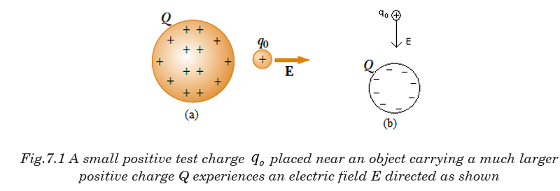
Electric field exists at a point if a test charge at that point experiences an electric - force.
The magnitude of the field is proportional to the number of field-lines per
unit area passing through a small surface normal to the lines.
The electric field strength or The electric field E at a point in space is defined
as the electric force Fe acting on a positive test charge q0 placed at that point
divided by the magnitude of the test charge:
The electric field strength or The electric field E at a point in space is defined
as the electric force Fe acting on a positive test charge q0 placed at that pointdivided by the magnitude of the test charge:
We require the test charge to be small enough to have a negligible effect on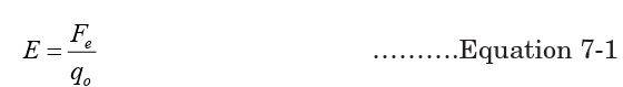
the charges on the sphere. A large test charge will cause a rearrangement of
the charges of the sphere due to induction and thus the test charge does nothave negligible effect on the sphere.
According to Coulomb’s law, the force exerted by q on the test charge is

Thus gravitational filed
 can be regarded as the gravitational force per
unit mass or the acceleration due to gravity. The gravitational field or
gravitational force per unit mass, is a useful concept because it does not
depend on the mass of the body on which the gravitational force is exerted;
likewise, the electric field or electric force per unit charge, is useful because
it does not depend on the charge of the body on which the electric force is
exerted
Example 7.1 Electric field due a single point charge1. Calculate the magnitude and direction of the electric field at a point P
The direction of the electric field is toward the charge q as shown in Fig.7.3a,
since we defined the direction as that of the force on a positive test charge
which here would be attractive.If q had been positive, the electric field would have pointed away, as in Fig. 7.3b.
NOTE There is no electric charge at point P. But there is an electric field
there. The only real charge is q
7.1.2 Electric potential and electric potential energyElectric potential is the potential energy per charge.
The change in potential energy between any two points, a and b, equals the
negative of the work done by the conservative force on an object as it moves
from point a to point b.
If we solve (7.01) and (7.03) for E, we find the general expression for potentialdifference at a point located a distance d from the charge
Example 7.2: Motion of a Proton in a Uniform Electric Field is only
valid for the case of a uniform electric field
1. A proton is released from rest in a uniform electric field that has a
magnitude of 8.0 104 / V m and is directed along the positive x axis (Fig.7.1). The proton undergoes a displacement of 0.50 m in the direction of E.
(a) Find the change in electric potential between points A and B.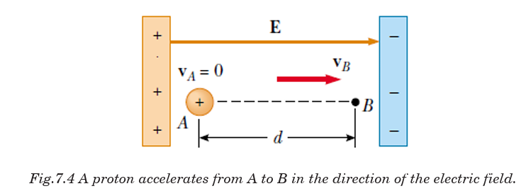
(b) Find the change in potential energy of the proton for this displacement.
(c) Use the concept of conservation of energy to find the speed of the proton
at point B (after completing the 0.50 m displacement in the electric field)
(d) What if the situation is exactly the same as that shown in Figure, but
no proton is present? Could both parts (A) and (B) of this example stillbe answered?
The negative sign means the potential energy of the proton decreases as it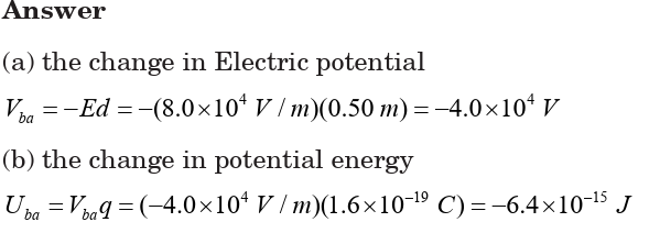
moves in the direction of the electric field; it gains kinetic energy and at the
same time loses electric potential energy.
(c) The charge–field system is isolated, so the mechanical energy of thesystem is conserved:
(d) Part (A) of the example would remain exactly the same because the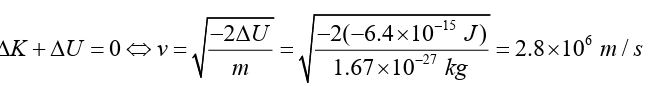
potential difference between points A and B is established by the source
charges in the parallel plates. The potential difference does not depend on
the presence of the proton, which plays the role of a test charge.
Part (B) of the example would be meaningless if the proton is not present. A
change in potential energy is related to a change in the charge–field system.
In the absence of the proton, the system of the electric field alone does not change
Positive charge moving in opposite direction of electric field
Now let us calculate the potential difference between two points A and B inthe field of a single positive charge q, see the Fig.7.5.
When a unit test charge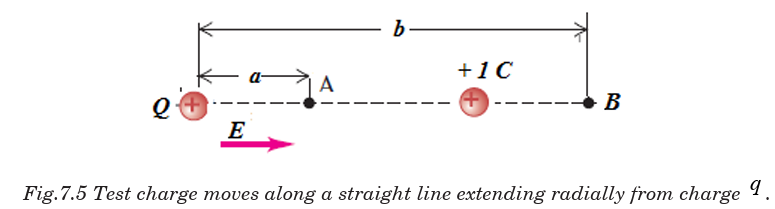

is placed in electric field E created by some source
charge distribution at a distance from the charge q placed at 0 in free
 space the electric force acting on the test charge is given by.
This force is conservative because the force between charges described by
Coulomb’s law is conservative. When the test charge is moved in the field by
some external agent, the work done by the field on the charge is equal to thenegative of the work done by the external agent causing the displacement.
The force is not constant during the displacement, the work done in takingthe charge from B to A, against the electric field E over short distance dr is
Thus the electric potential at an arbitrary point in an electric field
equals the work required per unit charge to bring a positive test charge
from infinity to that point
The potential near a positive charge is large and positive, and it decreases
toward zero at very large distances, Fig.7.6a. The potential near a negativecharge is negative and increases toward zero at large distances, Fig.7.6b.
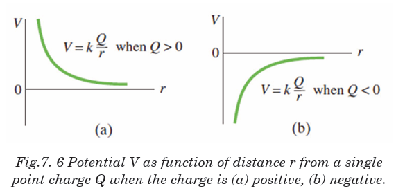
Example 7.3: Work required to bring two positive charges close

7.1.3 Equipotential Lines and Surfaces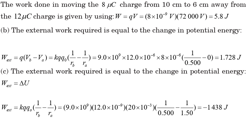
The electric potential can be represented by drawing equipotential lines
or equipotential surfaces. An equipotential surface is the one on which
all points are at the same potential. The potential difference between any
two points on the surface is zero, so no work is required to move a charge
from one point on the surface to the other. An equipotential surfacemust be perpendicular to the electric field at any point. If this was not
The fact that the electric field lines and equipotential surfaces are mutually
perpendicular, helps us locate the equipotentials when the electric field lines
are known. In a normal two-dimensional drawing, we show equipotential
lines, which are the intersections of equipotential surfaces with the planeof the electric field line.
In Fig. 7.7, a few of the equipotential lines are drawn (dashed green lines)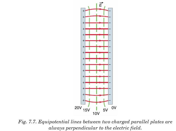
for the electric field (red lines) between two parallel plates maintained at a
potential difference of 20 V. The negative plate is arbitrarily chosen to bezero volts and the potential of each equipotential line is indicated.
7.1.4 Potential due to electric dipole
The field lines between two opposite and equal charges make what is calleda dipole. An electric dipole is a pair of point charges with equal magnitude
The equipotential lines for the case of two equal but oppositely charged
particles are shown in Fig. 7.8 as green dashed lines.
Unlike electric field lines, which start and end on electric charges,
equipotential lines and surfaces are always continuous curves, and continuebeyond the borders indicated in Figs. 7.7 and 7.8.
Electric Potential Energy with Several Point Charges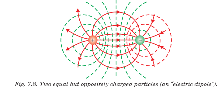
We obtain the electric potential resulting from two or more point charges by
applying the superposition principle. That is, the total electric potential
at some point P due to several point charges is the sum of the potentials
due to the individual charges. For a group of point charges, we can write thetotal electric potential at P in the form:
If the system consists of more than two charged particles, we can obtain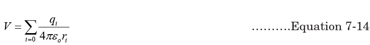
the total potential energy by calculating U for every pair of charges and
summing the terms algebraically. As an example, the total potential energyof the system of three charges shown in Fig.7. 10 is
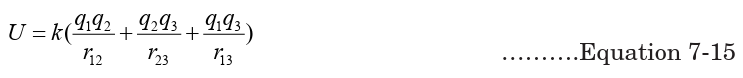
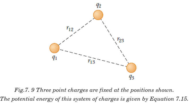
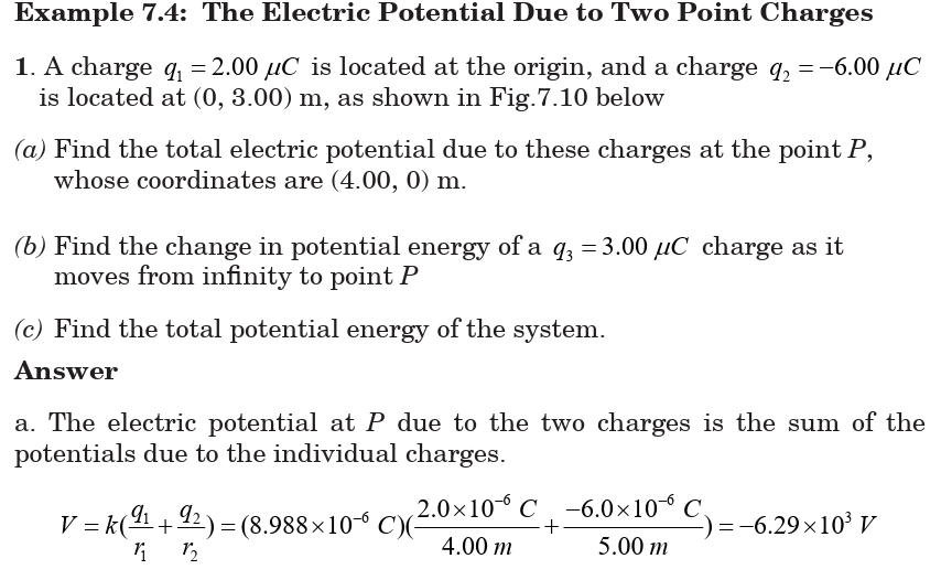
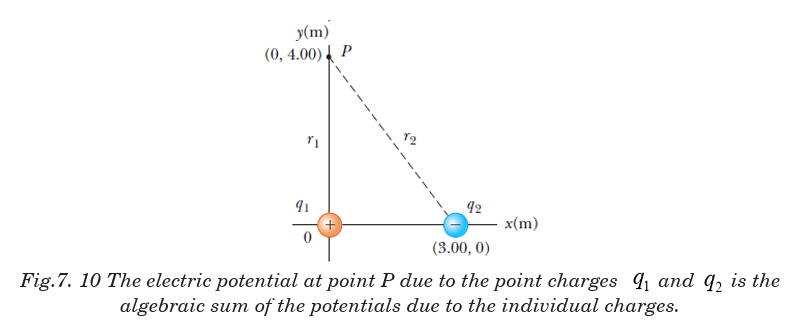
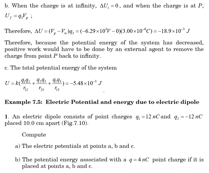
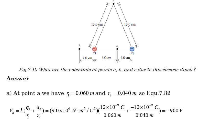
7.1.5 Conservation of electrical energy
Energy is conserved in the movement of a charged particle through an
electric field, as it is in every other physical situation. Electric charge
cannot be created or destroyed (though positive and negative charges can
neutralise each other).
Given a stationary test charge at a certain location, an applied electric field
will cause the charge to move to one end or the other, depending on the charge.
Positive test charges will move in the direction of the field; negative charges
will move in the opposite direction.
At the instant at which the field is applied, the motionless test charge has
zero kinetic energy, and its electric potential energy is at the maximum.
Now the charge accelerates, and its kinetic energy (due to motion) increases
as its potential energy decreases. The sum of energies is always constant.
The formula illustrating conservation of energy can be written in manyways, but all expressions are based on the simple premise of equating the

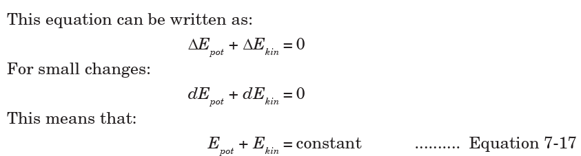
Application Activity 7.1

7.2 ELECTRODYNAMICS
This is the study of phenomena associated with charged bodies in motion
and varying electric and magnetic fields. Since a moving charge produces a
magnetic field, electrodynamics is concerned with effects such as magnetism,
electromagnetic radiation and electromagnetic induction, including some
practical applications as the electric generator and the electric motor.
This area of electrodynamics, often known as classical electrodynamics,
was first systematically explained by the physicist James Clarke Maxwell.
Maxwell’s equations, a set of differential equations, describe the phenomena
of this area with great generality. A more recent development is quantum
electrodynamics, which was formulated to explain the interaction of
electromagnetic radiation with matter, to which the laws of the quantum
theory apply.
When the velocities of the charged particles under consideration become
comparable with the speed of light, corrections involving the theory of
relativity must be made; this branch of the theory is called relativistic
electrodynamics. It is applied to phenomena involved with particle
accelerators and with electron tubes that are subject to high voltages and
carry heavy currents.
7.2.1 Cathode ray tube
The CRT is a vacuum tube in which a beam of electrons is accelerated and
deflected under the influence of electric or magnetic fields. The electron
beam is produced by an assembly called an electron gun located in the
neck of the tube. These electrons, if left undisturbed, travel in a straight
line path until they strike the front of the CRT, the “screen’’, which is coated
with a material that emits visible light when bombarded with electrons.
The operation of a CRT depends on thermionic emission, discovered
by Thomas Edison (1847–1931). Consider a voltage applied to two small
electrodes inside an evacuated glass “tube” as shown in Fig. 7.7: the cathode
is negative, and the anode is positive. If the cathode is heated (usually by
an electric current) so that it becomes hot and glowing, it is found that
negative charges leave the cathode and flow to the positive anode. These
negative charges are now called electrons, but originally they were called
cathode rays because they seemed to come from the cathode.
Fig.7.13 is a simplified sketch of a CRT which is contained in an evacuated
glass tube. A beam of electrons, emitted by the heated cathode, is accelerated
by the high-voltage anode and passes through a small hole in that anode. Theinside of the tube face on the right (the screen) is coated with a fluorescent
material that glows at the spot where the electron hits. Voltage applied
across the horizontal and vertical deflection plates can be varied to deflect
the electron beam to different spots on the screen. The instruments used in
the laboratory to display, measure and analyse the waveforms of differentcircuits is known as cathode ray oscilloscope.
7.2.2 TV and computer monitors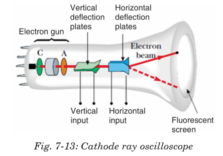
In TV and computer monitors, the CRT electron beam sweeps over the
screen in the manner shown in Fig.7.14 by carefully synchronizing voltages
applied to the deflection plates. This is called scanning.
During each horizontal sweep of the electron beam, the grid receives a
signal voltage that limits the flow of electrons at each instant during the
sweep; the more negative the grid voltage is, the more electrons are repelled
and fewer pass through, producing a less bright spot on the screen. Thus,
the varying grid voltage is responsible for the brightness of each spot on
the screen. At the end of each horizontal sweep of the electron beam, the
horizontal deflection voltage changes dramatically to bring the beam back
to the opposite side of the screen, and the vertical voltage changes slightly
so the beam begins a new horizontal sweep slightly below the previous one.
The difference in brightness of the spots on the screen forms the “picture”.
Colour screens have red, green, and blue phosphors which glow when
struck by the electron beam. The various brightnesses of adjacent red,
green and blue phosphors (so close together we don’t distinguish them)
produce almost any colour. With 30 new frames or pictures every second
(25 in countries with 50-Hz line voltage), a “moving picture” is displayed on
the TV screen. The commercial movies present 24 frames per second as thefilm runs.
7.2.3 Trajectory of a charge moving in a cathode ray tube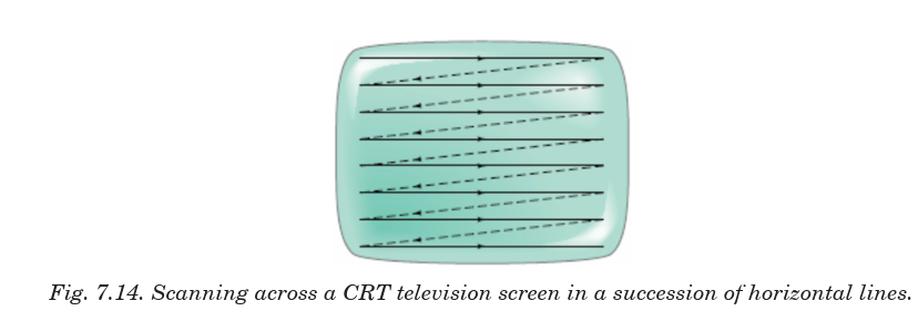
If electrons enter an electric field in a CRT acting at right angles to their
direction of motion, they are deflected from their original path. In Fig. 7.15,
a p.d is applied between the plates P and Q of length l, creates an electric
field of intensity E. Consider an electron of charge e, mass m and velocity ventering the field.
The value of z is measured from the centre of plates. Assume that the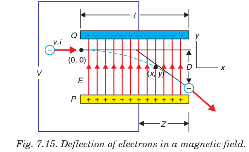
separation of plates is d.Field intensity E is given by;
Since E is vertical, there is no horizontal force acting on the electron. Hence,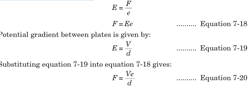
the horizontal velocity is not affected, i.e. it remains constant.
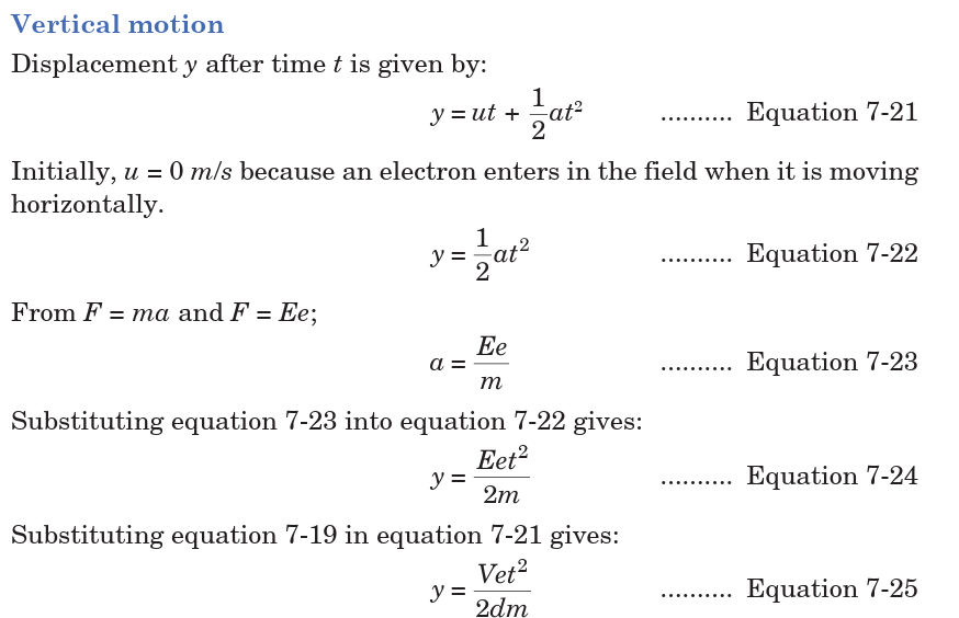
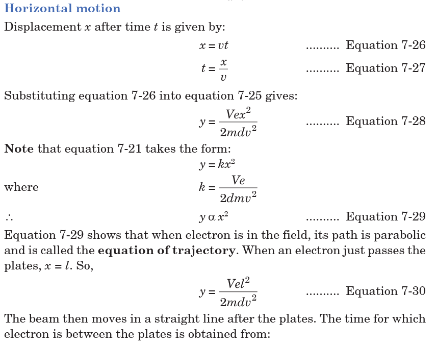

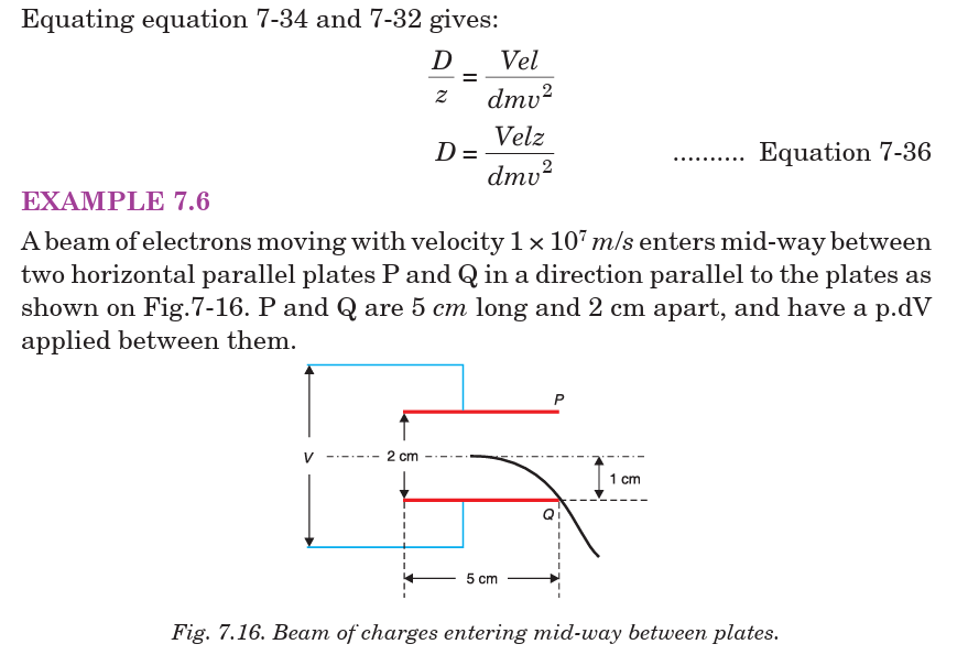
Application Activity 7.2
1. Fig. 7.17 shows two metal plates 2.0 cm long placed 5 mm apart.
A fluorescent screen is placed 20.0 cm from one of the plates. An
electron of kinetic energy 3.2 × 10⁻⁶ J is incident mid-way between
the plates. Calculate the voltage applied across the plates to deflect
the electron 2.1 cm on the screen. Assume that the electron movesthrough vacuum.
2. In the diagram of Fig. 7.18, P and Q are parallel metal plates each
of length l = 4 cm. A p.d of 12V is applied between P and Q. The
space between P and Q is virtual. A beam of electrons of speed 1.0
× 106 m/s is directed mid-way between P and Q at right angles to
the electric field between P and Q. Show that the electron beam
emerges from the space between P and Q at an angle of 64.6° to theinitial direction of the beam.
7.3 GRAVITATIONAL ENERGY
7.3.1 Newton’s Law of Universal Gravitation
In 1687 Newton published his work on the law of gravity in his treatise
Mathematical Principles of Natural Philosophy. Newton’s law of universal
gravitation states that
Every particle in the Universe attracts every other particle with a force
that is directly proportional to the product of their masses and inversely
proportional to the square of the distance between them.
If the particles have masses m1 and m2 and are separated by a distance r,
(Fig.7.24) the magnitude of this gravitational force is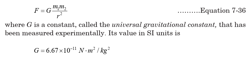
The form of the force law given by Equation 7.43 is often referred to as an
inverse square law because the magnitude of the force varies as the inversesquare of the separation of the particles.1
The magnitude of the force exerted by the Earth on a particle of mass m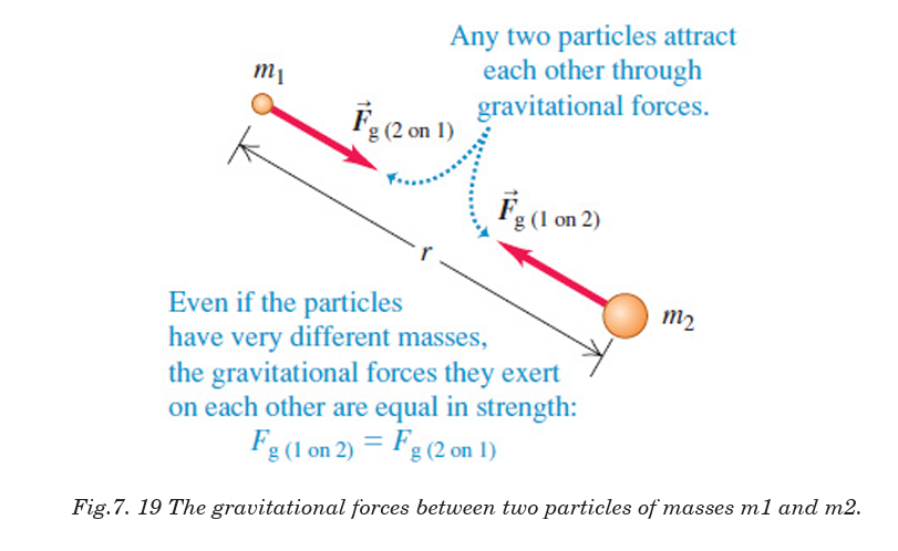
near the Earth’s surface is
This force is directed toward the center of the Earth.
7.3.2 Gravitational potential energy
Gravity is a conservative force, and we may define a potential energy
associate with it. Recall that the work you must do to lift a mass m from
one point to another is equal to the gain in potential energy. Work is doneagainst gravity only when the displacement is radial. Going sideways to r
The work done by the gravitational force when the body moves directly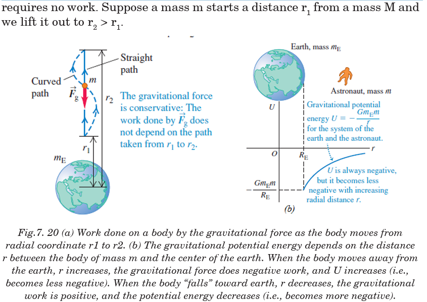
away from or toward the center of the earth is given by:
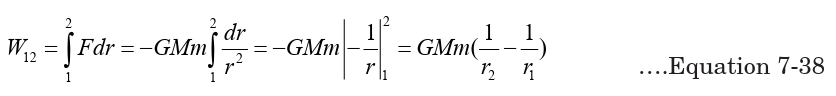
We define the corresponding gravitational potential energy U so that
This approximation is useful near the surface of the earth.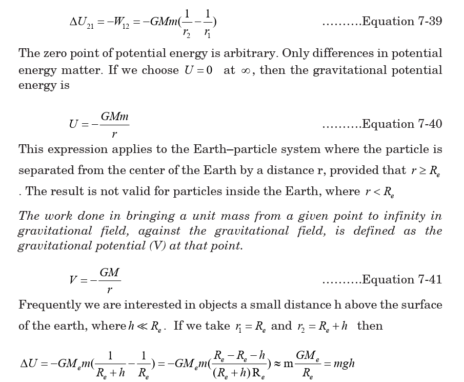
If the potential at infinity is taken as zero by convention, the negative signindicates that the potential at infinity (zero) is higher than the potential
The gravitational potential energy of a body of mass m due to the Earth’s
gravitational field is zero at infinity; when a body moves from infinity to a
point in the gravitational field, its potential energy decreases and kinetic
energy increases as shown in Fig.7.32b. Although Equation 7.42 was derivedfor the particle–Earth system, it can be applied to any two particles. That
is, the gravitational potential energy associated with any pair of particles
of masses m1 and m2 separated by a distance r is
When two particles are at rest and separated by a distance r, an external
agent has to supply energy at least equal to in order to
separate the particles to an infinite distance.
It is therefore convenient to think of the absolute value of the potential
energy as the binding energy of the system. If the external agent supplies
energy greater than the binding energy, the excess energy of the system
will be in the form of kinetic energy when the particles are at an infiniteseparation.
Example 7.7: Binding energy
1. Calculate the binding energy of the earth-sun system neglecting the
effect of the presence of other planets and satellites. Mass of earth = 6 × 10 24,
mass of sun = 3.3 ×10 5 times the mass of earth and the distance betweenearth and sun = 1.5 × 10 8 km.
Answer:The binding energy is the absolute value of the potential energy
We can extend this concept to three or more particles. In this case, the total
potential energy of the system is the sum over all pairs of particles.
Each pair contributes a term of the form given by Equation 7.36. For
example, if the system contains three particles, as in Fig.7.29, we find thatby superposition principle.
The absolute value of
 represents the work needed to separate the
particles by an infinite distance.
Example 7.8: Superposition of gravitational potential energy
1. A system consists of three particles, each of mass 5.00 g, located at
the corners of an equilateral triangle with sides of 30.0 cm. (a) Calculate
the potential energy of the system. (b) If the particles are releasedsimultaneously, where will they collide?
Answer
The gravitational potential energy of the system is the sum of the gravitational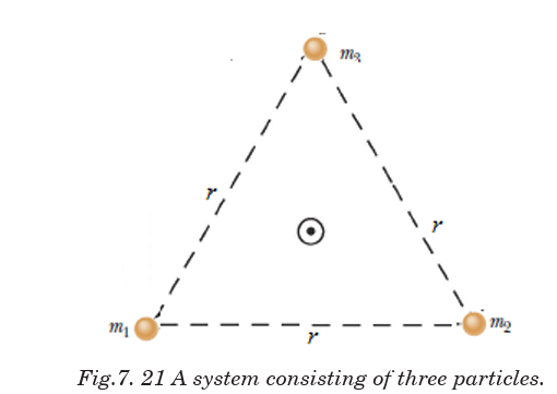
potential energies of all three pairs of particles
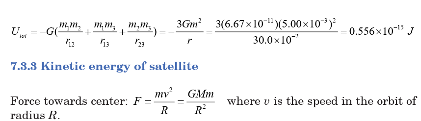
The total mechanical energy in a circular orbit is negative and equal to one
half the potential energy. Increasing the orbit radius r means increasing
the mechanical energy (that is, making E less negative). Fig.7.35 shows
the variation of K, U, and E with r for a satellite moving in a circular orbit
about a massive central body. Note that as r is increased, the kinetic energy(and thus also the orbital speed) decreases.
If the satellite is in a relatively low orbit that encounters the outer fringes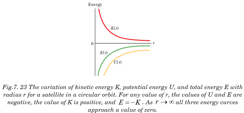
of earth’s atmosphere, mechanical energy decreases due to negative work
done by the force of air resistance; as a result, the orbit radius decreasesuntil the satellite hits the ground or burns up in the atmosphere.
Example 7.9
1. A satellite of mass 450 kg orbits the Earth in a circular orbit at 6.83 Mm
above the Earth’s surface. Find: (a) the potential energy (b) the kinetic
energy and (c) the total energy of the satellite
Answer(a) the distance between the satellite and the center of the Earth is
The total energy equals the negative of the kinetic energy.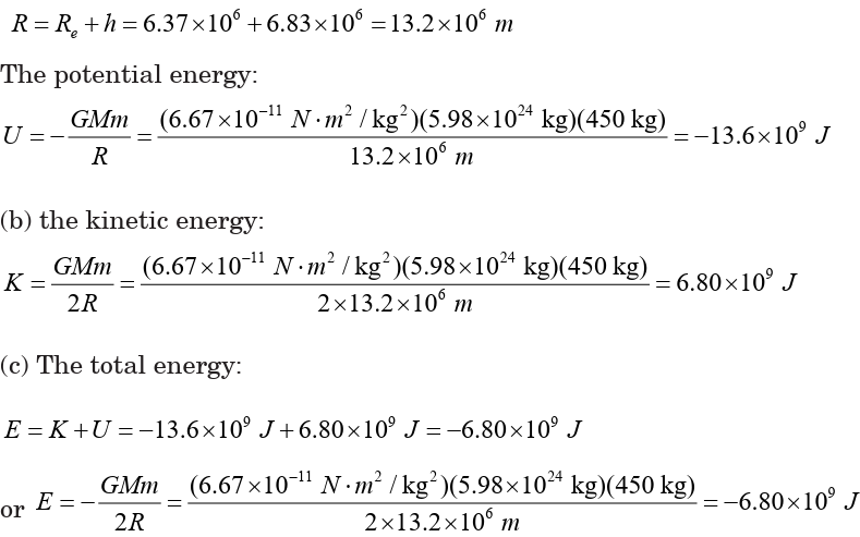
Escape speed:
Near the surface of the Earth, the force of attraction between the Earth
and some object is constant and equal to which is independent of the
height of the object above the Earth’s surface. The gravitational field near
the surface of the Earth is said to be uniform.
If we project an object vertically upward with initial speed in uniform
gravitational field, it will rise to a maximum height given by the law ofconservation of mechanical energy:
If we project an object upward with a very large initial speed so that the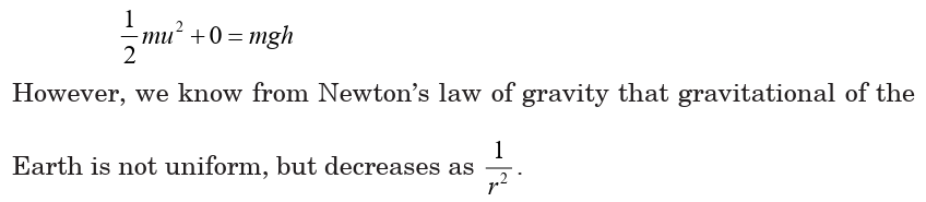
object moves a distance comparable to the radius of the Earth, we must
take into account the decrease in the gravitational force on the object tocalculate correctly the maximum height the object attains.
The minimum speed the object must have at the Earth’s surface in order to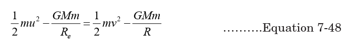
escape from the influence of the Earth’s gravitational field is escape speed.
Traveling at this minimum speed, the object continues to move farther andfarther away from the Earth as its speed asymptotically approaches zero.
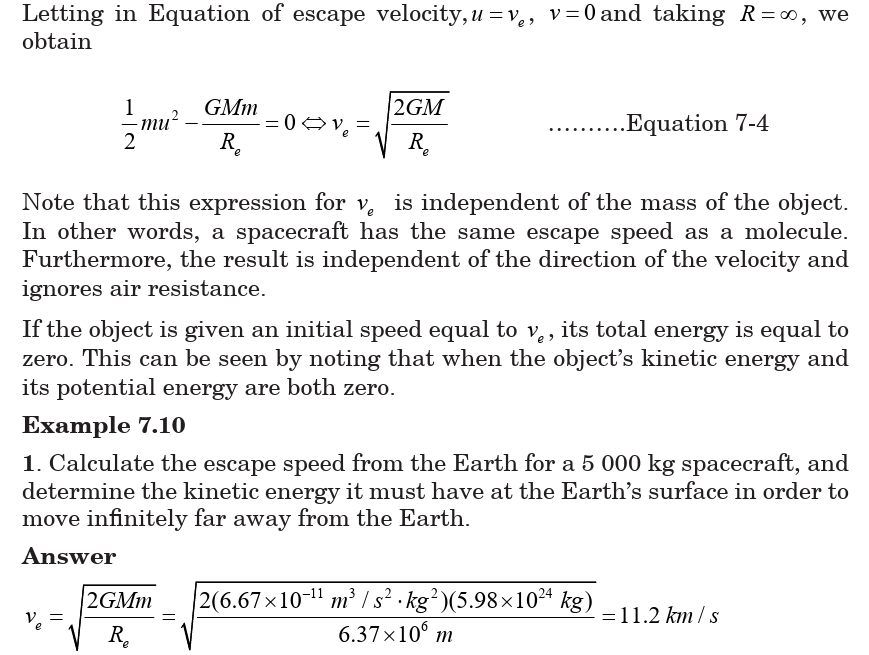


7.3.5 Relation between electric and gravitational field
There are many similarities between Coulomb’s law and Newton’s law of
universal gravitation:
• Both are inverse square laws that are also proportional to the product
of another quantity; for gravity it is the product of two masses, and for
the electric force it is the product of the two charges.
• The forces act along the line joining the centres of the masses or charges.
• The magnitude of the force is the same as the force that would be
measured if all the mass or charge is concentrated at a point at the
centre of the sphere.
Therefore, distance in both cases is measured from the centres of the
spheres. In both cases we are assuming that r is longer than the radius of
the object. However, the two forces also differ in some important ways:
The electric force can attract or repel, depending on the charges involved,whereas the gravitational force can only attract.
Just as a mass can be attracted gravitationally by more than one body at
once, so a charge can experience electric forces from more than one body
at once. Experiments have shown that the force between two charges can
be determined using Coulomb’s law independently of the other charges
present, and that the net force on a single charge is the vector sum of allthese independently calculated electric forces acting on it.
END OF UNIT ASSESSMENT
1. Four particles of masses m, 2 m, 3 m and 4 m are kept in sequence at the
corners of a square of side a. Find the magnitude of gravitational forceacting on a particle of mass m placed at the centre of the square.
2. Mass M is divided into two parts xM and (1 – x)M. For a given separation,
the value of x for which the gravitational attraction between the two
pieces becomes maximum. Find this maximum value of x.
3. Three identical point masses, each of mass 1 kg lies in the x – y plane at
points (0, 0), (0, 0.2 m) and (0.2 m, 0). Find the net gravitational force onthe mass at the origin.
4. Two positive charges sit in an (x, y)-coordinate system. The first one has
charge q1
= 0.40 µC and sits at (–0.30 m, 0). The second one has charge q2
= 0.30 µC and sits at (0, +0.30 m). Find the electric potential at the origin.
5. (a) Find the electric potential energy of the system of two chargesshown in the Figure 7.26.
(b) Find the electric potential energy of the system if a third charge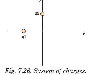
q3 = –0.10 µC is placed at the origin.
6. Two rectangular copper plates are oriented horizontally with one directly
above the other. They are separated by a distance of 25 mm. The plates
are connected to the terminals a 5.0 volt flashlight battery. The positive
plate (the one at the higher electric potential) is at the bottom; thenegative plate (the one at the lower electric potential) is at the top.
If an electron is placed on the upper plate, then released, with what speed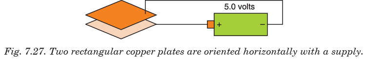
will it strike the lower plate? Use conservation of energy.
7. A charge of +2.82 µC sits in a uniform electric field of 12.0 N/C directed
at an angle of 60° above the +x axis. The charge moves from the origin(point A) to the point (1.40 m, 0) (point B) on the x-axis.
• a. Find the force exerted on the charge by the electric field.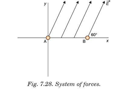
• b. Find the work done on the charge by the electric field as the
charge moves from A to B.
• c. Find the change in the charge’s electric potential energy as it
moves from A and B.• d. Find the electric potential difference between points A and B.
UNIT SUMMARY
Electric Field and Electric Potential Due to a Point Charge
The direction of electric field is taken to be the direction of the force it would exert ona positive test charge.

Electric Potential Energy and Potential Difference
The work done by a conservative force in moving an object between any two
positions is independent of the path taken. Hence, we define the potentialenergy for electrostatic force mathematically as:
Equipotential Lines and Surfaces
An equipotential surface is one on which all points are at the same potential.
An equipotential surface must be perpendicular to the electric field
at any point.
Potential due to Electric Dipole
Unlike electric field lines, which start and end on electric charges,
equipotential lines and surfaces are always continuous closed curved.
Conservation of Electrical Energy
At the instant at which the field is applied, the motionless test charge has
zero kinetic energy, and its electric potential energy is at a maximum. Then,
the charge accelerates, and its kinetic energy (from motion) increases as itspotential energy decreases. The sum of energies is always constant.
Cathode Ray Tube (CRT)
The CRT is a vacuum tube in which a beam of electrons is accelerated and
deflected under the influence of electric or magnetic fields.
These electrons, if left undisturbed, travel in a straight-line path until they
strike the screen of the CRT, which is coated with a material that emits
visible light when bombarded with electrons.
TV and Computer Monitors
In TV and computer monitors, the CRT electron beam sweeps over the
screen in the manner of carefully synchronized voltages applied to the
deflection plates and is called scanning.
Trajectory of a charge moving in a cathode ray tube
The equation of motion of a charge in a field is calculated by consideringvertical and horizontal displacements and is given by:
This equation shows that when electron is in the field, its path is parabolic
and is called the equation of trajectory.
The vertical deflection D of electron on the screen from initial direction ofmotion can be obtained by using equation:
Electrodynamics
When the velocities of the charged particles under consideration become
comparable with the speed of light, corrections involving the theory of
relativity must be made; this branch of the theory is called relativistic
electrodynamics.
Gravitational Potential
The gravitational potential V at a point is defined numerically as work donein taking a uniform mass from infinity to that point.
Escape Velocity for a Planet
If the rocket is fired from the surface of the earth with velocity v such that
it just escapes from the influence of the earth’s gravitational pull. Then thisvelocity is called escape velocity.
Energy Conservation in Gravitational Fields
Conservation of energy tells us that the total energy of the system is
conserved, and in this case, the sum of kinetic and potential energy must
be constant. This means that every change in the kinetic energy of a system
must be accompanied by an equal but opposite change in the potential energy.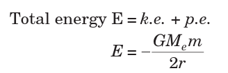
UNIT 8:MOTION IN ORBITS
Key unit competence: Evaluate Newton’s law of gravitation and
apply Kepler’s laws of planetary motion.
Unit Objectives:
By the end of this unit I will be able to;
◊ Explain the terms, concept and characteristics of waves properly.
◊ Explain the properties of waves.
◊ Explain the behavior of waves in vibrating strings and applicationsof waves properly.
Introductory Activity
People have always enjoyed viewing stars and planets on clear, dark
nights. It is not only the beauty and variety of objects in the sky that is
so fascinating, but also the search for answers to questions related to
the patterns and motions of those objects.
Until the late 1700s, Jupiter and Saturn were the only outer planets
identified in our solar system because they were visible to the naked
eye. Combined with the inner planets the solar system was believed
to consist of the Sun and six planets, as well as other smaller bodies
such as moons. Some of the earliest investigations in physical science
started with questions that people asked about the night sky.
i) Based on the scenario above and the observation from the
picture. Briefly summarize what is illustrated in the picture.
ii) What is the name of belt separating the largest and smallest planets?
iii) Explain why you think the moon doesn’t fall on the earth.
iv) Why don’t we fly off into space rather than remaining on the
Earth’s surface? Explain your idea.v) Explain why planets move across the sky.
8.1. INTRODUCTION
Gravity is the mysterious force that makes everything fall down towards
the Earth. But after research it has turned out that all objects have gravity.
It’s just that some objects, like the Earth and the Sun, have a stronger
gravity than others. How much gravity an object has depends its mass.
It also depends on how close you are to the object. The closer you are, thestronger the gravity.
Gravity is very important to our everyday lives. Without Earth’s gravity
we would fly right off it. If you kicked a ball, it would fly off forever. While
it might be fun to try for a few minutes, we certainly can’t live without
gravity. Gravity also is important on a larger scale. It is the Sun’s gravity
that keeps the Earth in orbit around the Sun. Life on Earth needs the Sun’s
light and warmth to survive. Gravity helps the Earth to stay at just theright distance from the Sun, so it’s not too hot or too cold.
8.2. NEWTON’S LAW OF GRAVITATION
This is also called the universal law of gravitation or inverse square
law. It states that “the gravitational force of attraction between two
masses m1 and m2 is directly proportional to the product of masses
and inversely proportional to the square of their mean distance
apart.” Remember two objects exert equal and opposite force of gravitation
on each other.
Notes:
• The value of G in the laboratory was first determined by Cavendishusing the torsional balance.
Properties of Gravitational Force
• It is always attractive in nature while electric and magnetic force can
be attractive or repulsive.
• It is independent of the medium between the particles while electric
and magnetic forces depend on the nature of the medium between the particles.
• It holds good over a wide range of distances. It is found true for
interplanetary to interatomic distances.
• It is a central force, i.e. it acts along the line joining the centres of two
interacting bodies.
• It is a two-body interaction, i.e. gravitational force between two particles
is independent of the presence or absence of other particles; so, the
principle of superposition is valid, i.e. force on a particle due to numberof particles is the resultant of forces due to individual particles, i.e.
• It is a conservative force, i.e. work done by it is path independent or
work done in moving a particle round a closed path under the action
of gravitational force is zero.
• It is an action reaction pair, i.e. the force with which one body (say,
earth) attracts the second body (say, moon) is equal to the force with
which moon attracts the earth. This is in accordance with Newton’s
third law of motion.
8.3. KEPLER’S LAWS OF PLANETARY MOTION
Planets are large natural bodies rotating around a star in definite orbits.
The planetary system of the star sun, called solar system, consists of eight
planets, viz. Mercury, Venus, Earth, Mars, Jupiter, Saturn, Uranus, and
Neptune . Out of these planets mercury is the smallest, closest to the sun.
jupiter is the largest and has the maximum number of moons. Venus is
closest to the earth and the brightest planet. Kepler, after a life time study,
worked out three empirical laws which govern the motion of these planetsand are known as Kepler’s laws of planetary motion. These are stated below.
1st Law: This law is called the law of orbits and it states that planets move
in ellipses with the sun as one of their foci. It can also be stated that planetsdescribe ellipses about the sun as one focus. (Fig. 8.2)
2nd Law: This is called the law of areas and states that the line joining the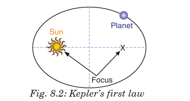
sun and the planet sweeps out equal areas in equal periods of time. (Fig. 8.3)

3rd Law: The law of periods states that the square of the period T of
revolution of any planet is proportional to the cube of its mean distance Rfrom the sun. (Fig. 8.4)
8.4. VERIFICATION OF KEPLER’S THIRD LAW OF
PLANETARY MOTION
Assuming that a planet’s orbit is circular (which is not exactly correct but is
a good approximation in most cases), then the mean distance from the sun
is constant –radius. Suppose, a planet of mass m2 moving around the sun of mass m1
If the motion of the planet is circular, there are two types of forces:
(a) Gravitational force of attraction F1 between the sun and the planet,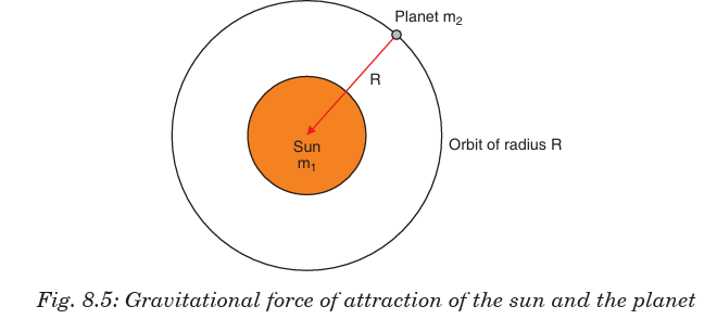

EXAMPLE 8.1:
The distance of a planet from the sun is 5 times the distance between the
earth and the sun. What is the time period of revolution of the planet?
Solution:According to Kepler’s law

Background information:
Kepler’s third law (the Harmonic Law), relates the orbital period of a
planet (that is, the time it takes a planet to complete one orbit) to
its mean distance from the Sun. This law states that the closest
planets travel at the greatest speeds and have the shortest orbital periods.
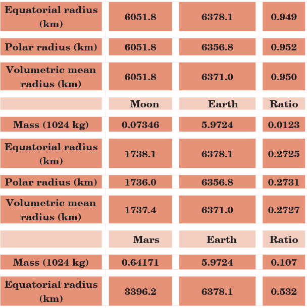
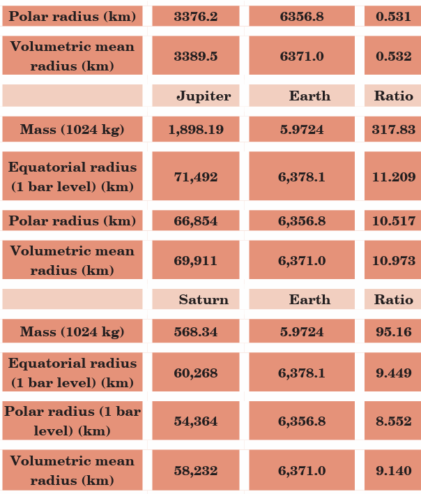


Source of data: lunar and planetary science by National Aeronautics and
Space Administration (NASA)
Use the data provided in the tables above and find the orbital period for
each orbital radius for each planet. Enter the data into spreadsheets
and plot line graphs for the data, with each planet’s orbital radius on theX-axis and its orbital period on the Y-axis.
Describe any general trends you see: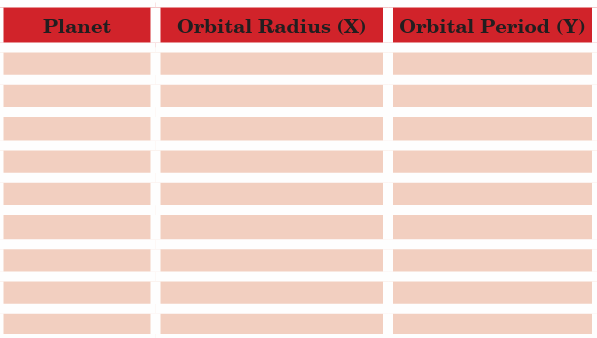
a) Is there a systematic relationship between period and radius for the
planets for each case?
b) How would you describe this relationship in words?
c) Is the relationship you observe consistent with Kepler’s third law?d) How could you improve your test for consistency?
Application Activity 8.1
Using the cross and down clues write the correct words in the numberedgrid below.
Across
6. The second largest planet with many rings.
7. This planet’s blue color is the result of absorption of red light by
methane in the upper atmosphere.
8. A small body that circles the Sun with a highly elliptical orbit.
9. An object in orbit around a planet.
10. A large cloud of dust and gas which escapes from the nucleus of an
active comet.
DOWN
1. It is the brightest object in the sky except for the Sun and the Moon.
2. The largest object in the solar system.
3. The only planet whose English name does not derive from Greek/
Roman mythology.
4. An area seen as a dark spot on the photosphere of the Sun.
5. This planet is more than twice as massive as all the other planets combined.
8.5. ACCELERATION DUE TO GRAVITY AT THE
SURFACE OF THE EARTH
The force of attraction exerted by the earth on a body is called gravitational
pull or gravity. We know that when force acts on a body, it produces acceleration.
Therefore, a body under the effect of gravitational pull must accelerate.
The acceleration produced in the motion of a body under the effect of gravity
is called acceleration due to gravity (g). Consider a body of mass m lying on the surface
of earth. Then gravitational force on the body is given by:
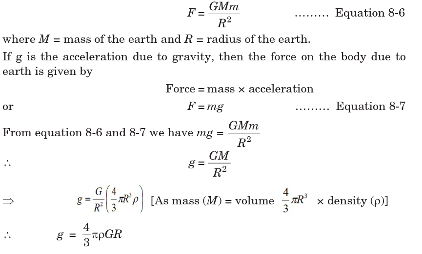
• Acceleration due to gravity is a vector quantity and its direction is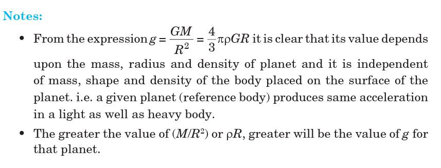
always towards the centre of the planet.
• Dimensions of [g] = [LT –2]
• Average value of g is taken as 9.8 m/s2 or 981 cm/s2, on the surface of
the earth at mean sea level.
• In general, the value of acceleration due to gravity vary due to the
following factors: (a) Shape of the earth, (b) Height above the earth
surface, (c) Depth below the earth surface and (d) Axial rotation of the earth.
EXAMPLE 8.4:
The moon’s radius is (1/4)th of that of earth and its mass is 1/80 times that
of the earth. If g represents the acceleration due to gravity on the surfaceof the earth, what is acceleration due to gravity on the surface of the moon?
8.6. VARIATION OF ACCELERATION DUE TO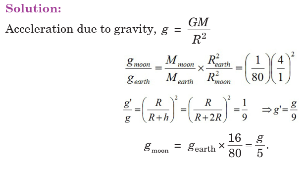
GRAVITY WITH HEIGHT
Consider a particle placed at a height h above the surface of the earth whereacceleration due to gravity is g′ as shown on the figure below.

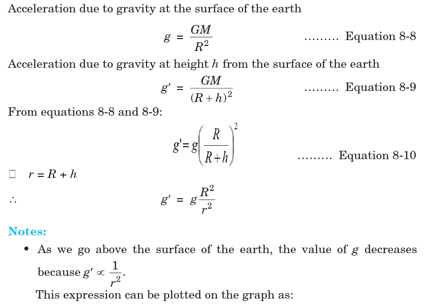

EXAMPLE 8.5: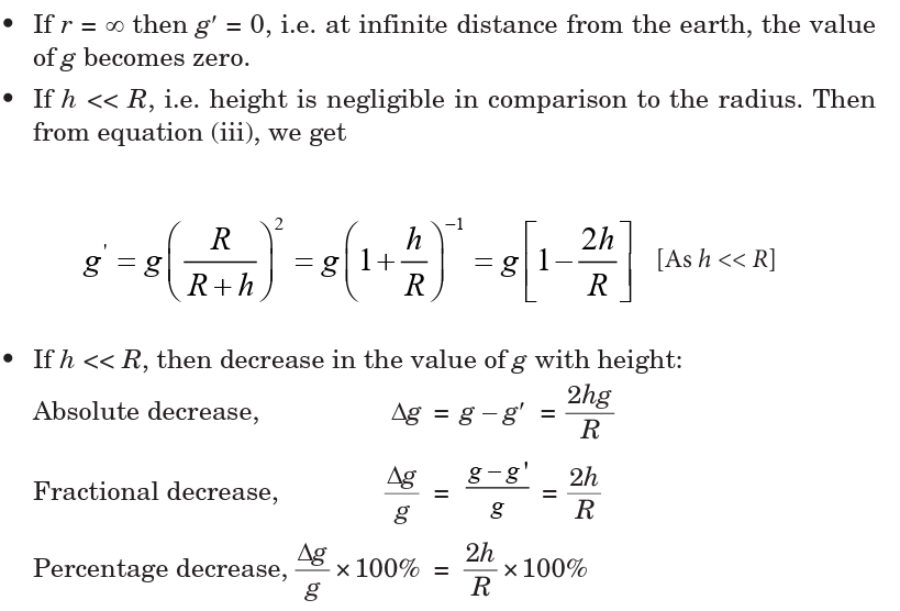
The acceleration of a body due to the attraction of the earth (radius R) is
g. Find the acceleration due to gravity at a distance 2R from the surface of the earth.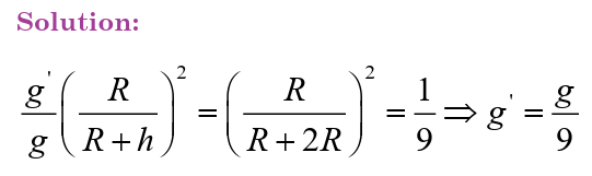
EXAMPLE 8.6:
Find the height of the point above the earth’s surface, at which acceleration
due to gravity becomes 1% of its value at the surface is (Radius of the earth = R).
Notes:
• The value of g decreases on going below the surface of the earth. From
equation 8-12, we get g′ ∝ (R – d). So it is clear that if d increases, thevalue of g decreases.
Combining the graphs for variation of acceleration due to gravity below and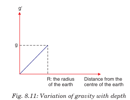
above the surface of the earth will give the graph as shown below:
EXAMPLE 8.7: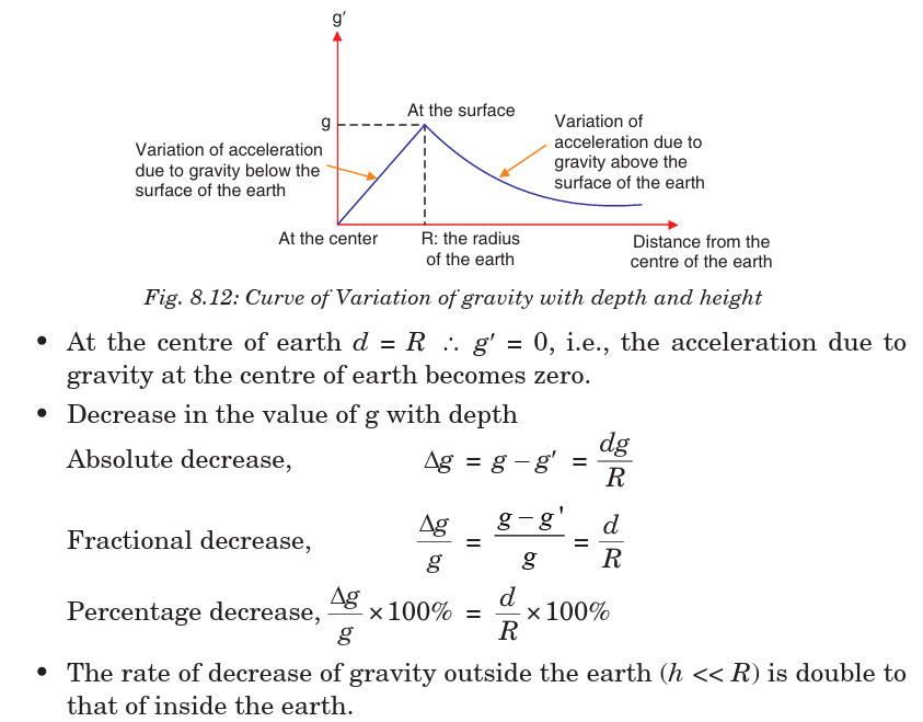
Weight of a body of mass m decreases by 1% when it is raised to height h
above the earth’s surface. If the body is taken to a depth h in a mine, whatis the change in its weight?
8.8. VARIATION IN G DUE TO ROTATION OF EARTH
As the earth rotates, a body placed on its surface moves along the circular
path and hence experiences centrifugal force. Due to it, the apparent weight
of the body decreases.
Since the magnitude of centrifugal force varies with the latitude of the
place, therefore the apparent weight of the body varies with latitude due tovariation in the magnitude of centrifugal force on the body.
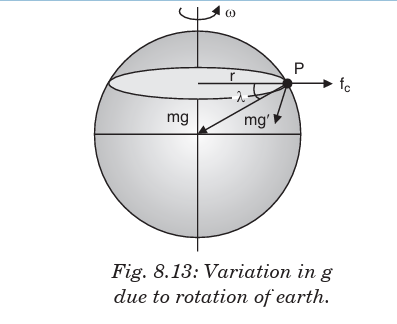

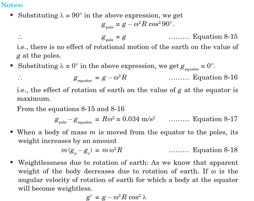

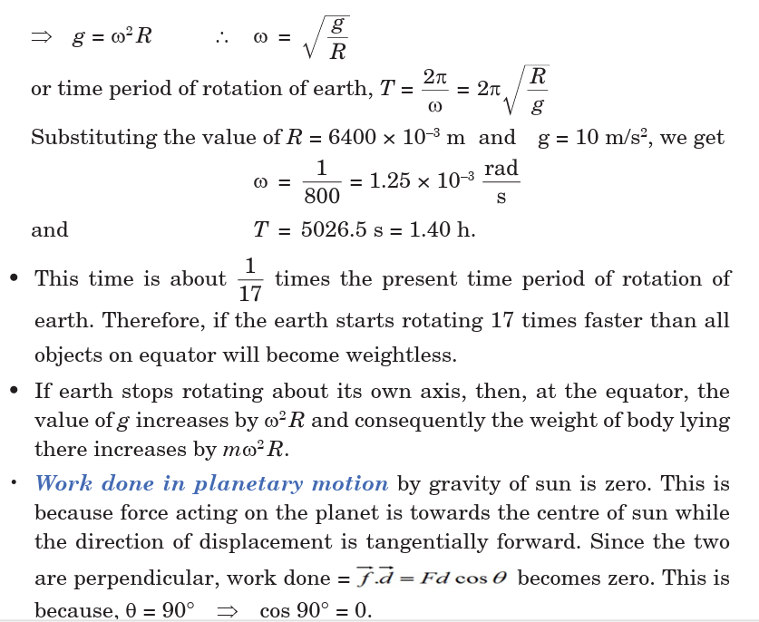
EXAMPLE 8.9:
What is the angular velocity of the earth with which it has to rotate so that
acceleration due to gravity on 60° latitude becomes zero? (Radius of earth= 6400 km. At the poles g = 10 ms–2)
8.9. VARIATION OF ‘G’ DUE TO SHAPE OF EARTH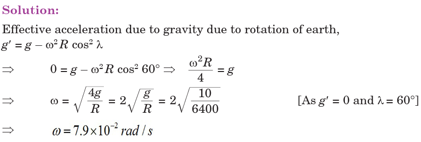
Earth is elliptical in shape. It is flattened at the poles and bulged out at the equator.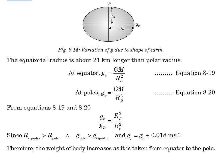
8.10. ROCKETS
A rocket is a device that produces thrust by ejecting
stored matter. A rocket moves forward when gas expelled from
the rear of a rocket pushes it in the opposite direction. From
Newton’s laws of motion, for every action, there is an equal
and opposite reaction. In a rocket, fuel is burned to make a
hot gas and this hot gas is forced out of narrow nozzles in the
back of the rocket, propelling the rocket forward.
Spacecraft Propulsion
Spacecraft Propulsion is characterized in general by its complete integration
within the spacecraft (e.g. satellites). Its function is to provide forces and
torques in (empty) space to:
• transfer the spacecraft: used for interplanetary travel
• position the spacecraft: used for orbit control• orient the spacecraft: used for altitude control
The jet propulsion systems for launching rockets are also called primary
propulsion systems. Spacecrafts, e.g. satellites, are operated by secondary
propulsion systems.
Characteristics of Spacecraft Propulsion Systems
In order to fulfill altitude and orbit operational requirements of spacecraft,
spacecraft propulsion systems are characterized by:
• Very high velocity increment capability (many km/s)
• Low thrust levels (1 mN to 500 N) with low acceleration levels
• Continuous operation mode for orbit control
• Pulsed operation mode for altitude control
• Predictable, accurate and repeatable performance (impulse bits)
• Reliable, leak-free long time operation (storable propellants)
• Minimum and predictable thrust exhaust impingement effects
Classification of Propulsion Systems
Spacecraft propulsion can be classified according to the source of energy
utilized for the ejection of propellant:
• Chemical propulsion use heat energy produced by a chemical
reaction to generate gases at high temperature and pressure in a
combustion chamber. These hot gases are accelerated through a
nozzle and ejected from the system at a high exit velocity to produce
thrust force.
• Electric propulsion uses electric or electromagnetic energy to eject
matter at high velocity to produce thrust force.
• Nuclear propulsion uses energy from a nuclear reactor to heat
gases which are then accelerated through a nozzle and ejected fromthe system at a high exit velocity to produce thrust force.
Notes: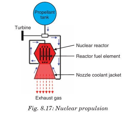
• While chemical and electric systems are used for the propulsion of
today’s spacecrafts, nuclear propulsion is still under study. Therefore,
only chemical and electric propulsion will be dealt with in this book.
8.11. SATELLITES
A satellite is an artificial or a natural body placed in orbit round the earth
or another planet in order to collect information or for communication.
Communication satellites are satellites that are used specifically to
communicate. Part of that communication will be the usual commands and
signals we get from any satellite. The payload of the satellite consists of
huge collection of powerful radio transmitters and a big dish or something
like that, to enable it to talk to things on the ground. And we’ll use them
to transmit TV signals, to transmit radio signals, and in some cases, it
might be to be transmit internet signals. So, all of that gets turned into
radio somehow and transmitted up into space and then bounced back downsomewhere else.
There is only one main force acting on a satellite when it is in orbit, and
that is the gravitational force exerted on the satellite by the Earth. This
force is constantly pulling the satellite towards the centre of the Earth.
A satellite doesn’t fall straight down to the Earth because of its velocity.
Throughout a satellite’s orbit there is a perfect balance between the
gravitational force due to the Earth, and the centripetal force necessary tomaintain the orbit of the satellite.
8.11.1. Orbital Velocity of Satellite.
Satellites are natural or artificial bodies describing orbit around a planet under
its gravitational attraction. Moon is a natural satellite while INSAT
1B is an artificial satellite of the earth. Condition for establishment of artificial satellite
is that the centre of orbit of satellite must coincide with centreof earth or satellite must move around great circle of earth.
Orbital velocity of a satellite is the velocity required to put the satellite into
its orbit around the earth. For revolution of satellite around the earth, thegravitational pull provides the required centripetal force.

Notes:
• Orbital velocity is independent of the mass of the orbiting body and is
always along the tangent of the orbit, i.e. satellites of deferent masses
have the same orbital velocity, if they are in the same orbit.
• Orbital velocity depends on the mass of central body and radius of orbit.
• For a given planet, greater the radius of orbit, lesser will be the orbitalvelocity of the satellite
• Orbital velocity of the satellite when it revolves very close to the
surface of the planet:
EXAMPLE 8.10: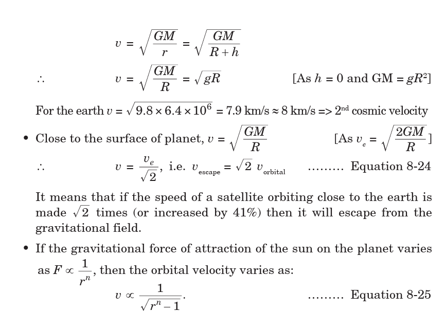
Two satellites A and B go round a planet P in circular orbits having radii
4R and R respectively. If the speed of the satellite A is 3v, what is the speedof the satellite B?
Orbital velocity increases by 0.5%.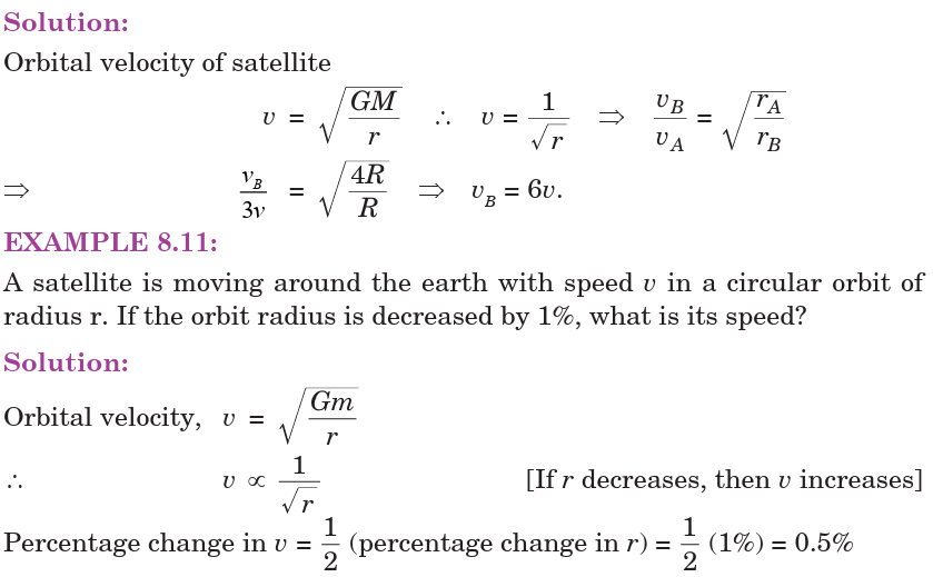
8.11.2. Time Period of SatelliteIt is the time taken by satellite to go once around the earth.

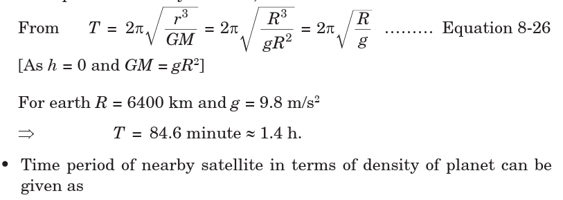
EXAMPLE 8.12: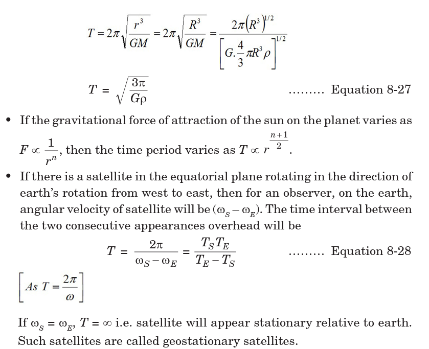
A satellite is launched into a circular orbit of radius ‘R’ around earth while
a second satellite is launched into an orbit of radius 1.02 R. What is the
percentage difference in the time periods of the two satellites?
Solution:Orbital radius of second satellite is 2% more than the first satellite.


EXAMPLE 8.13:
What is the periodic time of a satellite revolving above Earth’s surface at aheight equal to R, where R is the radius of Earth?
By knowing the value of time period we can calculate the height of satellite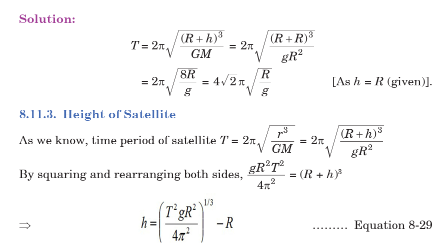
the surface of the earth.
EXAMPLE 8.14:
Given radius of earth ‘R’ and length of a day ‘T’, what is the height of ageostationary satellite

EXAMPLE 8.15:
A satellite is revolving round the earth in circular orbit at some height above
surface of the earth. It takes 5.26 × 10³ seconds to complete a revolution
while its centripetal acceleration is 9.32 m/s2. What is the height of satelliteabove the surface of earth? (Radius of the earth 6.37 × 10⁶ m)
8.11.4. Geostationary Satellite
The satellite which appears stationary relative to earth is called
geostationary or geosynchronous satellite, e.g. communication satellite.
A geostationary satellite always stays over the same place above the earth.
Such a satellite is never at rest. It appears stationary due to its zero relative
velocity with respect to that place on earth.
The orbit of a geostationary satellite is known as the parking orbit.
Notes:
• It should revolve in an orbit concentric and coplanar with the equatorial plane.
• Its sense of rotation should be same as that of earth about its own
axis, i.e. in anti-clockwise direction (from west to east).
• Its period of revolution around the earth should be the same as that of
earth about its own axis.T = 24 h = 86400 s
8.11.5. Energy of Satellite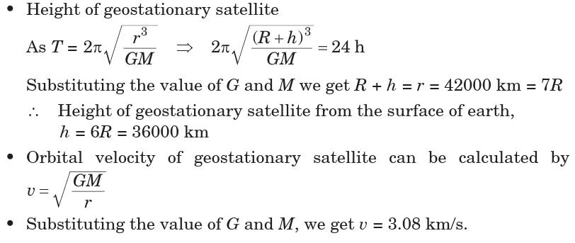
When a satellite revolves around a planet in its orbit, it possesses both
potential energy (due to its position against gravitational pull of earth) andkinetic energy (due to orbital motion).
Notes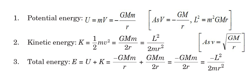
• Kinetic energy, potential energy or total energy of a satellite depends
on the mass of the satellite and the central body and also on the radius
of the orbit.
• From the above expressions we can say that
Kinetic energy (K) = – (Total energy)
Potential energy (U) = 2 (Total energy)Potential energy (K) = – 2 (Kinetic energy)
• If the orbit of a satellite is elliptical, then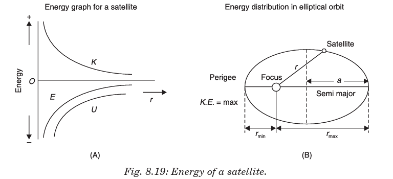

2- = constant; where a is semi-major axis.
(b) Kinetic energy (K) will be maximum when the satellite is closest
to the central body (at perigee) and maximum when it is farthest
from the central body (at apogee).
(c) Potential energy (U) will be minimum when kinetic energy is
maximum, i.e. when satellite is closest to the central body (at
perigee). Potential energy is maximum when kinetic energy is
minimum, i.e. the satellite is farthest from the central body (at apogee).
• Binding Energy: Total energy of a satellite in its orbit is negative.
Negative energy means that the satellite is bound to the central body
by an attractive force and energy must be supplied to remove it from
the orbit to infinity. The energy required to remove the satellite fromits orbit to infinity is called Binding Energy of the system, i.e.
Application Activity 8.2
1. The distance of Neptune and Saturn from sun are nearly 1013 and
1012 metres respectively. Assuming that they move in circular orbits,
what will be their periodic times in the ratio?
2. A spherical planet far out in space has a mass M0
and diameter D0
A particle of mass m falling freely near the surface of this planet
will experience an acceleration due to gravity which is equal to g.
Derive the expression of g in terms of D.
3. At surface of earth, weight of a person is 72 N. What is his weight at
height R/2 from surface of earth (R = radius of earth)?
4. Assuming earth to be a sphere of a uniform density, what is the
value of gravitational acceleration in a mine 100 km below the
earth’s surface (Given R = 6400 km)?
5. If the gravitational force between two objects was proportional to
1/R; where R is separation between them, then a particle in circular
orbit under such a force would have its orbital speed v proportional
to which value?
6. An earth satellite S has an orbital radius which is 4 times that of acommunication satellite C. What is its period of revolution?
8.12 TYPES AND APPLICATIONS OF SATELLITE SYSTEMS
Four different types of satellite orbits have been identified depending on
the shape and diameter of each orbit:
• GEO (Geo-stationary earth orbit)
• MEO (medium earth orbit)
• LEO (Low earth orbit) and• HEO (Highly elliptical orbit)
GEO (geostationary orbit)
A geostationary orbit or geosynchronous equatorial orbit (GEO) has a
circular orbit 35,786 kilometres above the Earth’s equator and following the
direction of the Earth’s rotation. An object in such an orbit has an orbital
period equal to the Earth’s rotational period (one sidereal day) and thusappears motionless, at a fixed position in the sky, to ground observers.
Most common geostationary satellites are either weather satellites or
communication satellites relaying signals between two or more ground
stations and satellites that broadcast signals to a large area on the planet.
All radio and TV, whether satellite etc. are launched in this orbit.
Advantages of Geo-Stationary Earth Orbit
1. It is possible to cover almost all parts of the earth with just 3 geo satellites.
2. Antennas need not be adjusted every now and then, but can be fixed
permanently.
3. The life-time of a GEO satellite is quite high usually around 15 years.
Disadvantages of Geo-Stationary Earth Orbit
1. Larger antennas are required for northern/southern regions of the earth.
2. High buildings in a city limit the transmission quality.
3. High transmission power is required.
4. These satellites cannot be used for small mobile phones.
5. Fixing a satellite at Geo stationary orbit is very expensive.
LEO (Low Earth Orbit)
Satellites in low Earth orbits are normally military reconnaissance satellites
that can locate out tanks from 160 km above the Earth. They orbit the earth
very quickly, one complete orbit normally taking 90 minutes. However,
these orbits have very short lifetimes in the order of weeks compared withdecades for geostationary satellites. Simple launch vehicles can be used to
Low Earth Orbit is used for things that we want to visit often with the
Space Shuttle, like the Hubble Space Telescope and the International Space
Station. This is convenient for installing new instruments, fixing things
that are broken, and inspecting damage. It is also about the only way we
can have people go up, do experiments, and return in a relatively short time.
A special type of LEO is the Polar Orbit. This is a
LEO with a high inclination angle (close to
90 degrees). This means the satellite travels over the poles.
Advantages of Low Earth Orbit
1. The antennas can have low transmission power of about 1 watt.
2. The delay of packets is relatively low.
3. Useful for smaller foot prints
Disadvantages of Low Earth Orbit
1. If global coverage is required, it requires at least 50-200 satellites in this orbit.
2. Special handover mechanisms are required.
3. These satellites involve complex design.
4. Very short life: Time of 5-8 years. Assuming 48 satellites with a life-time
of 8 years each, a new satellite is needed every 2 months.
5. Data packets should be routed from satellite to satellite.
MEO (Medium Earth Orbit) or ICO (Intermediate Circular Orbit)
Medium Earth Orbit satellites move around the earth at a height of 6000
20000 km above earth’s surface. Their signal takes 50 to 150 milliseconds
to make the round trip. MEO satellites cover more earth area than LEOs
but have a higher latency. MEOS are often used in conjunction with GEOsatellite systems.
Advantages of Medium Earth Orbit
1. Compared to LEO system, MEO requires only a dozen satellites.
2. Simple in design.3. Requires very few handovers.
Disadvantages of Medium Earth Orbit
1. Satellites require higher transmission power.
2. Special antennas are required.
HEO (Highly Elliptical Orbit)
A satellite in elliptical orbit follows an oval-shaped path. One part of the orbit
is closest to the centre of Earth (perigee) and another part is farthest away
(apogee). A satellite in this type of orbit generally has an inclination angle of
64 degrees and takes about 12 hours to circle the planet. This type of orbitcovers regions of high latitude for a large fraction of its orbital period
8.13. COSMIC VELOCITY FIRST, SECOND AND THIRD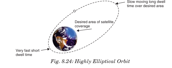
The cosmic velocity is the initial velocity which a body must have to be able
to overcome the gravity of another object.We have:
1. The first cosmic velocity
2. Second cosmic velocity3. The third cosmic velocity
8.13.1. The first cosmic velocity
As you know the satellites which were sent by a human are orbiting around
the Earth. They had to be launched with a very high velocity, namely, withthe first cosmic velocity.
This velocity can be calculated using the gravitational force and the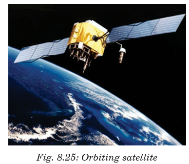
centripetal force of the satellite:
Satellites must have extremely high velocity to orbit around the Earth. In
fact, satellites go around the Earth at the height h = 160 km in order not tobreak into the atmosphere.
8.13.2. Second cosmic velocity (escape velocity)
In the previous section we calculated the velocity which a body has to have
to go around the Earth, which means that we calculated the value of the first
cosmic velocity. Now it is time to give attention to calculating the second cosmic
velocity -it is the speed needed to “break free” from the gravitational
attraction of the Earth or celestial body to which it is attract.
In order to understand this issue we should know something about kineticand potential energy.
This value is calculated using the fact that as the body moves away from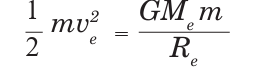
the Earth, the kinetic energy decreases and the potential energy increases.
At infinity, both the energies are equal to zero, because, when the distance
between the body and the Earth increases, the kinetic energy decreases andat infinity, it has the value of 0.
The potential energy at infinity has got the highest value but if we put
infinity in the previous formula, we will obtain zero (or an extremely small
fraction).The value of the second cosmic velocity is calculated as follows;
We can also obtain the value of the second cosmic velocity by multiply the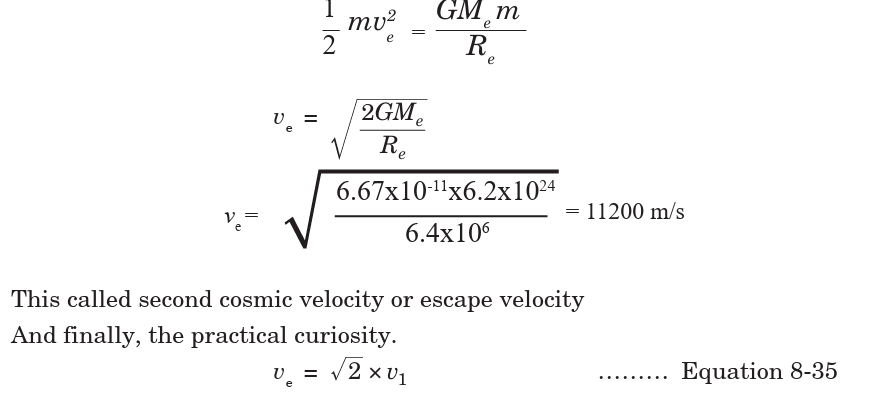
value of the first cosmic velocity by the square root of two.
8.13.3. The 3rd cosmic velocity
The third cosmic velocity is the initial velocity which a body has to have to
leave the Solar System and its value is:
v3= 16.7 km/s at solar system
At the surface of the Earth, this velocity is about 42 km/s. But due to its
revolution, it is enough to launch the body with velocity 16.7 km/s in the
direction of this movement.
8.13.4. The fourth cosmic velocityIt is the initial velocity which a body should have to leave the Milky Way.
This velocity is about 350 km/s but since Sun is going around the galaxy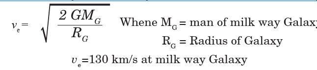
centre, so it is enough to launch the body with the velocity of 130 km/s inthe direction of the Sun’s movement.
Application Activity 8.3
The grid shown below contains terms used in this unit. Highlight at
least 25 terms. Construct 10 sentences in context of motion in orbitsusing those words found in the grid.
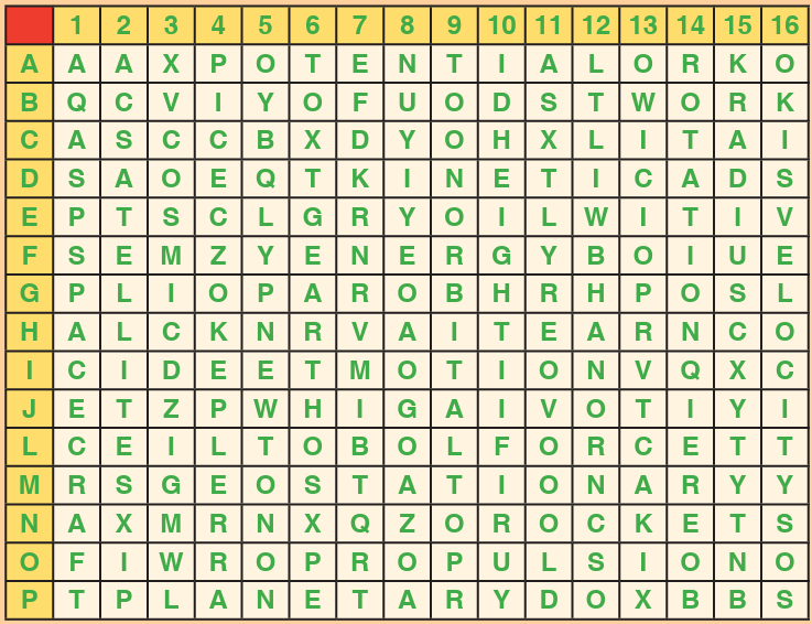
Application Activity 8.4
Using the Across and Down clues, write the correct words in thenumbered grid below.
ACROSS
1. The only natural satellite of Earth.
5. An object in orbit around a planet.
6. The smallest planet and farthest from the Sun.
7. This planet probably got this name due to its red color and is
sometimes referred to as the Red Planet.
9. This planet’s blue color is the result of absorption of red light by
methane in the upper atmosphere.
10. It is the brightest object in the sky except for the Sun and the moon.
DOWN
2. Named after the Roman god of the sea.
3. The closest planet to the Sun and the eighth largest.
4. A large cloud of dust and gas which escapes from the nucleus of an
active comet.8. The largest object in the solar system.
END OF UNIT ASSESSMENT
1. A satellite A of mass m is at a distance of r from the centre of the earth.
Another satellite B of mass 2m is at distance of 2r from the earth’s
centre. What is the ratio of their time periods?
2. Mass of moon is 7.34 × 10²² kg. If the acceleration due to gravity
on the moon is 1.4 m/s2, find the radius of moon. Use (G = 6.67 ×
10–11 Nm2/kg2).
3. A planet has mass 1/10 of that of earth, while radius is 1/3 that of
earth. If a person can throw a stone on earth surface to a height of 90 m,to what height will he be able to throw the stone on that planet?
4. If the distance between centres of earth and moon is D and the mass of
earth is 81 times the mass of moon, then at what distance from centre ofearth the gravitational force will be zero?
5. What is the depth d at which the value of acceleration due to gravity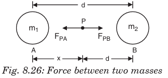
becomes n/1
times the value at the surface? [R = radius of the earth]
6. The distance between centre of the earth and moon is 384000 km. If the
mass of the earth is 6 × 1024 kg and G = 6.67 × 10⁻¹¹ Nm2/kg2, what is the
speed of the moon?
7. One project after deviation from its path, starts moving round the earth
in a circular path at radius equal to nine times the radius at earth R,
what is its time?
8. A satellite A of mass m is revolving round the earth at a height ‘r’ from
the centre. Another satellite B of mass 2m is revolving at a height 2r.What is the ratio of their time periods?
UNIT SUMMARY
Newton’s law of gravitation
This is also called the universal law of gravitation or inverse square law.
And sates that “the gravitational force of attraction between two masses
m1 and m2 is directly proportional to the product of masses and inverselyproportional to the square of their mean distance apart.”
Kepler’s laws of planetary motion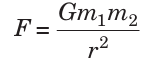
1st Law: This law is called the law of orbits and states that planets move in
ellipses with the sun as one of their foci. It can also be stated that planets
describe ellipses about the sun as one focus.
2nd Law: This is called the law of areas and states that the line joining the
sun and the planet sweeps out equal areas in equal periods of time.
3rd Law: The law of periods states that the square of the periods T of
revolution of planets are proportional to the cubes of their mean distancesR from the sun.
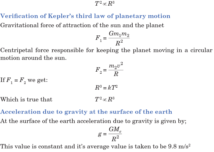
The depth d is measured from the surface of the earth. The value of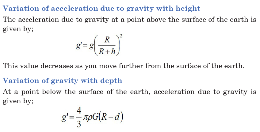
acceleration due to gravity increases as we move towards the surface. At
centre of earth g = 0.
Variation in g Due to Rotation of Earth
As the earth rotates, a body placed on its surface moves along the circular
path and hence experiences centrifugal force, due to which the apparent
weight of the body decreases.By solving, the acceleration due to gravity is given by;

Rockets and spacecraft
A rocket is a device that produces thrust by ejecting stored matter. Spacecraft
Propulsion is characterized in general by its complete integration withinthe spacecraft (e.g. satellites).
Satellites
A satellite is an artificial body placed in orbit round the earth or anotherplanet in order to collect information or for communication.
It is seen that angular momentum of satellite depends on both the mass of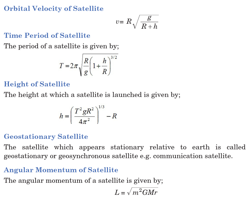
orbiting and central body as well as the radius of orbit.
Energy of Satellite
When a satellite revolves around a planet in its orbit, it possesses both
potential energy (due to its position against gravitational pull of earth) andkinetic energy (due to orbital motion).
Types and applications of Satellite Systems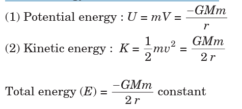
• GEO (Geo-stationary earth orbit)
• MEO (medium earth orbit)
• LEO (Low earth orbit) and
• HEO (Highly elliptical orbit)
Cosmic velocity
The first cosmic velocity
v1= 7900 m/s
Second cosmic velocity
This is also called the escape velocity, v2 = 11200 m/s
Third cosmic velocity
The third cosmic velocity is the initial velocity which a body has to have to
escape the Solar System and its value is given by;
v3 = 16.7 km/sUNIT 9:ATOMIC MODELS AND PHOTOELECTRIC EFFECT

Key unit competence: Evaluate the atomic models and photoelectric
effect
Unit Objectives:
By the end of this unit I will be able to;
◊ Describe different atomic models by explaining their concepts and
drawbacks.
◊ Explain the photoelectric effect and its applications in everyday life.
Introductory Activity
1. Basing on the figure above,
a. How is the structure/arrangement of balls shown in the figure
related to an atom? You can use chemistry knowledge from
O’level.
b. Relate the arrangement of electrons in an atom to how the
balls in the figure above are arranged.
c. Explain how movement of particles in an atom leads to release
or absorption of energy
4. It is important to realise that a lot of what we know about the
structure of atoms has been developed over a long period of time.
This is often how scientific knowledge develops, with one person
building on the ideas of someone else.In attempt to explain an
atom, different scientists suggest different models. An atomic model
represents what the structure of an atom could look like, based on
what we know about how atoms behave. It is not necessarily a true
picture of the exact structure of an atom.
a. Why did these scientists use the word Model not exact structure
of an atom?
b. Can you explain some of the scientific models that tried to
explain the structure of an Atom?
9.0 INTRODUCTION
An atomic theory is a model developed to explain the properties and
behaviours of atoms. An atomic theory is based on scientific evidence
available at any given time and serves to suggest future lines of research
about atoms.
The concept of an atom can be traced to debate among Greek philosophers
that took place around the sixth century B.C. One of the questions that
interested these thinkers was the nature of matter. Is matter continuous
or discontinuous? If you could break a piece of chalk as long as you wanted,
would you ever reach some ultimate particle beyond which further division
was impossible? Or could you keep up that process of division forever?
Such questions need the knowledge on the atomic structure and interaction
with photoelectric effect to be answered. This theory is helpful in Chemistry
(Atomic structure), Security (Alarm systems), Medicine, Archaeology, etc.
9.1 STRUCTURE OF THE ATOM AND THOMSON’S MODEL
structure of the atom
An atom is the smallest particle of an element that retains again the
characteristics or the properties of that element during chemical reaction.
By the early 1900s scientists were able to break apart the atoms into
particles that they called the electron and the nucleus which is made of
proton and neutrons.
• Electrons
Electrons surround the dense nucleus of an atom. It is the smallest
subatomic particle with a mass of
and a negative electric charge. The electron is also one of the few
elementary particles that is stable, meaning it can exist by itself for a long period of time.
Most other elementary particles can exist independently for only a fraction of a second.
Electrons have no detectable shape or structure.
The electrons revolve around the nucleus in fixed trajectory (orbits) called
energy levels or shell. These shells have the names K, L, M, N, etc…
The shell of atom just prior to the outermost shell of an atom cannot
accommodate more than 8 electrons even it has a capacity to accommodate
more electrons. The outermost shell (last shell) which contains electrons
is called the conduction shell or valence shell. On each electron shell, we
can meet N=2n2 electrons, where N is the number of the electron shell.
The valence electrons which are not very attached to the nucleus are called
free electrons. The free electrons can be easily detached from the atom
by application of a small external energy (usually thermal energy by
increasing the temperature).
• Protons
Proton is a subatomic particle with a positive charge. The charge is equal
and opposite to that of an electron. The mass of a proton is 1840 times
that of an electron. Thus the mass of an atom is mainly due to protons
and neutrons. The proton is one of the few elementary particles that are
stable—that is, it can exist by itself for a long period of time. The number of
protons is called the atomic number (Z).
In normal atom, the number of electrons is equal to the number of protons.
The atomic number (Z) of an atom is equal to the number of protons (or
electrons) contained in atom.
• Neutron
Neutron is a subatomic particle with a mass almost equal to the mass of a
proton. It has no electric charge. The neutron is about 10-13 cm in diameter
and weighs The number of protons and neutrons
is called nucleons number, or, alternatively, the mass number (A). The mathematical
relationship between atomic number (Z), mass number (A) and neutron numberis


Thomson’s model
English scientist Joseph John Thomson’s cathode ray experiments (end
of the 19th century) led to the discovery of the negatively charged electron
and the first ideas of the structure of these indivisible atoms. In his model
of the atom, Sir J J Thomson (1856-1940) suggested a model of atom as
“The atom is like a volume of positive charge with electrons embeddedthroughout the volume, much like the seeds in watermelon.”Fig.9.4
Success and Failure of Thomson’s model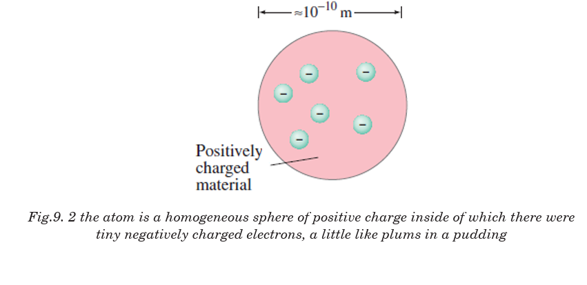
Thomson’s model explained the phenomenon of thermionic emission,
photoelectric emission and ionization. The model fails to explain the
scattering of a-particles and it is the origin of spectral lines observed in the
spectrum of hydrogen and other atoms.
9.2 RUTHERFORD’S ATOMIC MODEL
Rutherford performed experiments on the scattering of alpha particles byextremely thin gold foils and made the following observations;
Note:
• Some of a-particles are deflected through small angles.
• A few a-particles (1 in 1000) are deflected through the angle more
than 90°.
• A few a-particles (very few) returned back i.e. deflected by 180°.
• Distance of closest approach (Nuclear dimension) is the minimum
distance from the nucleus up to which the a-particle approach. It is
denoted by r0 . From figure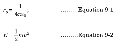
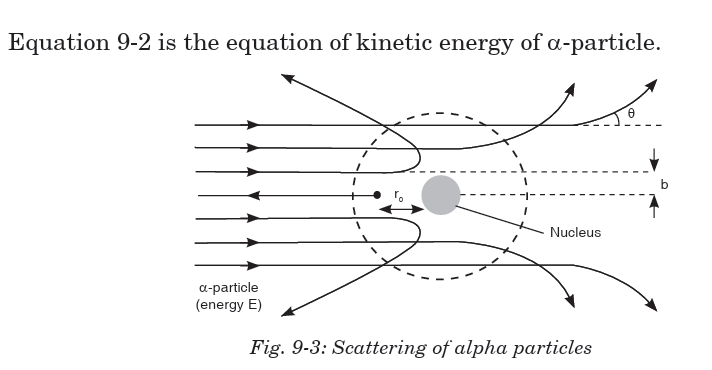
From these experiments a new model of the atom was born called
Rutherford’s planetary model of the atom. The following conclusions were
made to describe the atomic structure:
• Most of the mass and all of the charge of an atom is concentrated in a
very small region called atomic nucleus.
• Nucleus is positively charged and it’s size is of the order of 10–15 m .
• In an atom there is maximum empty space and the electrons revolve
around the nucleus in the same way as the planets revolve around the sun.
Drawbacks : Rutherford's model could not explain the following:
• Stability of atom: It could not explain the stability of atom because
according to classical electrodynamics, an accelerated charged particle
should continuously radiate energy. Thus, an electron moving in a
circular path around the nucleus should also radiate energy and thus
move into and smaller orbits of gradually decreasing radius and itshould ultimately fall into nucleus.
• According to this model, the spectrum of atom must be continuous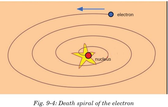
whereas practically it is a line spectrum.
• It did not explain the distribution of electrons outside the nucleus.
9.3 BOHR’S ATOMIC MODEL
Bohr proposed a model for hydrogen atom which is also applicable for
some lighter atoms in which a single electron revolves around a stationary
nucleus of positive charge Ze (called hydrogen like atom). Bohr’s model is
based on the following postulates:
• Each electron moves in a circular orbit centered at the nucleus.
• The centripetal force needed by the electron moving in a circle is
provided by electrostatic force of attraction between the nucleus and
electrons.• The angular momenta p of electrons are whole number multiples of


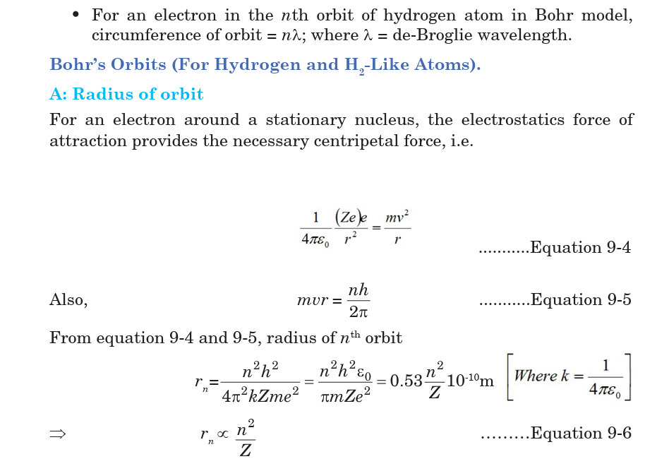
Drawbacks of Bohr’s atomic model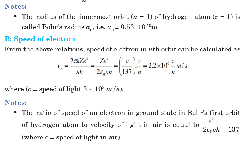
• It is valid only for single valency atoms, e.g. : H, He+2, Li+, Na+1 etc.
• Orbits were taken as circular but according to Sommerfield these are
elliptical.
• Intensity of spectral lines could not be explained.
• Nucleus was taken as stationary but it also rotates on its own axis.
• It could not explain the minute structure in spectral lines.
• This does not explain the Zeeman effect (splitting up of spectral lines
in magnetic field) and Stark effect (splitting up in electric field)
• This does not explain the doublets in the spectrum of some of the
atoms like sodium (5890x10-10m & 5896x 10-10m)
9.4 ENERGY LEVELS AND SPECTRAL LINES OF
HYDROGEN
When hydrogen atom is excited, it returns to its normal unexcited state (or
ground state) by emitting the energy it had absorbed earlier. This energy
is given out by the atom in the form of radiations of different wavelengths
as the electron jumps down from a higher orbit to a lower orbit. Transition
from different orbits causes different wavelengths. These constitute spectral
series which are characteristic of the atom emitting them. When observed
through a spectroscope, these radiations are imaged as sharp and straightvertical lines of a single colour.
The spectral lines arising from the transition of electron forms a spectra
series. Mainly there are five series and each series is named after its
discover as Lyman series, Balmer series, Paschen series, Brackett series
and Pfund series. First line of the series is called first member, for which
line wavelength is maximum (λmax). Last line of the series (n2= ∞) is called
series limit, for which line wavelength is minimum (λmin).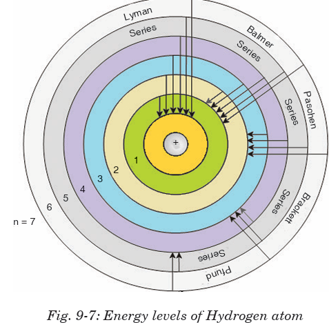
9.5 THERMIONIC EMISSION ( THERMO ELECTRONIC
EMISSION)
Thermionic emission means the discharge of electrons from heated materials.
It is widely used as a source of electrons in conventional electron tubes (e.g.,
television picture tubes) in the fields of electronics and communications. The
phenomenon was first observed (1883) by Thomas A. Edison as a passage ofelectricity from a filament to a plate of metal inside an incandescent lamp.
In thermionic emission, the heat supplies some electrons with at least the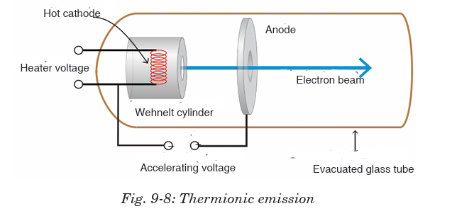
minimal energy required to overcome the attractive force holding them in
the structure of the metal. This minimal energy, called the work function,
is the characteristic of the emitting material and the state of contaminationof its surface.
9.6 APPLICATIONS OF CATHODE RAYS
9.6.1 Cathode ray oscilloscope
The cathode-ray oscilloscope (CRO) is a common laboratory instrument that
provides accurate time and amplitude measurements of voltage signals over
a wide range of frequencies. Its reliability, stability and ease of operationmakes it suitable as a general purpose laboratory instrument.
The main part of the C.R.O. is a highly evacuated glass tube housing parts
which generates a beam of electrons, accelerates them, shapes them into
a narrow beam and provides external connections to the sets of plates
changing the direction of the beam. The heart of the CRO is a cathode-raytube shown schematically in Fig.9-10;
Working of a C.R.O
• An indirectly heated cathode provides a source of electrons for the
beam by ‘boiling’ them out of the cathode.
• The anode is circular with a small central hole. The potential of anode
creates an electric field which accelerates the electrons, some of which
emerge from the hole as a fine beam. This beam lies along the central
axis of the tube.
• The grid has the main function of concentrating the beam at the
centre controlling the potential of the grid that controls the number
of electrons for the beam, and hence the intensity of the spot on the
screen where the beam hits.
• X and Y are two deflection plates. The X plates are used for deflecting
the beam from left to right (the x-direction) by means of the ‘ramp’
voltage. The Y plates are used for deflection of the beam in the vertical
direction. Voltages on the X and Y sets of plates determine where the
beam will strike the screen and cause a spot of light.
• The screen coated on the inside with a fluorescent material which
shines with green light (usually) where the electrons are striking.
9.6.2 TV tubes
The picture tube is the largest component of a television set, consisting
of four basic parts. The glass face panel is the screen on which images
appear. Suspended immediately behind the panel is a steel shadow mask,
perforated with thousands of square holes. (Connected to the mask is a
metal shield to neutralize disruptive effects of the Earth’s magnetic field.)
The panel is fused to a glass funnel, which comprises the rear of the picture
tube. The very rear of the funnel converges into a neck, to which an electrongun assembly is connected.
The inside of the panel is painted with a series of very narrow vertical
stripes, consisting of red, green and blue phosphors. These stripes are
separated by a narrow black graphite stripe guard band. When struck by an
electron beam, the phosphors will illuminate, but the graphite will not. This
prevents colour impurity by ensuring that the electron beam only strikes
the phosphor stripes it is intended to light.
The electron beam is generated by the electron gun assembly, which houses
three electron guns situated side-by-side. Each of the three guns emits an
electron beam (also called a cathode ray) into the tube, through the maskand onto the panel.
Because the three beams travel side-by-side, the holes in the mask ensure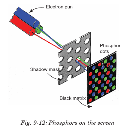
that each beam, because of its different angle of attack, will hit only a
specific phosphor stripe; red, green or blue. The three phosphors, lighted
in different combinations of intensity, can create any visible colour when
viewed from even a slight distance.
The three electron beams are directed across the screen through a series of
electromagnets, called a yoke, which draw the beams horizontally across
the screen in line at a time. Depending on the screen size, the beam draws
about 500 lines across the entire screen. Each time, the phosphors light up
to produce an image.
The electron guns and the yoke are electronically synchronized to ensure
the lines of phosphors are lighted properly to produce an accurate image. The
image lasts only for about a 1/30th of a second. For that reason, the picture
must be redrawn 30 times in a second. The succession of so many picturesproduces the illusion of movement, just like the frames on movie film.
9.7 FLUORESCENCE AND PHOSPHORESCENCE
Fluorescence is the emission of light by a substance that has absorbed light
or other electromagnetic radiation. It is a form of photoluminescence.
In most cases, the emitted light has a longer wavelength, and therefore,
lower energy than the absorbed radiation. However, when the absorbed
electromagnetic radiation is intense, it is possible for one electron to absorb
two photons; this two-photon absorption can lead to emission of radiation
having a shorter wavelength than the absorbed radiation. The emitted
radiation may also be of the same wavelength as the absorbed radiation,
termed “resonance fluorescence”.
Fluorescence occurs when an orbital electron of a molecule or atom relaxes
to its ground state by emitting a photon of light after being excited to a
higher quantum state by some type of energy. The most striking examples
of fluorescence occur when the absorbed radiation is in the ultraviolet region
of the spectrum, and thus invisible to the human eye, and the emitted light
is in the visible region.
Phosphorescence is a specific type of photoluminescence related to
fluorescence. Unlike fluorescence, a phosphorescent material does not
immediately re-emit the radiation it absorbs. Excitation of electrons to
a higher state is accompanied with the change of a spin state. Once in a
different spin state, electrons cannot relax into the ground state quickly
because the re-emission involves quantum mechanically forbidden energy
state transitions. As these transitions occur very slowly in certain materials,
absorbed radiation may be re-emitted at a lower intensity for up to severalhours after the original excitation.
9.8 PHOTOELECTRIC EMISSION LAWS
Law 1:
The photocurrent is directly proportional to the intensity of light and is
independent of frequency.
Explanation
According to quantum theory, each photon interacts only with each
electron. When the intensity is increased more photons will come and they
will interact with more electrons. This will increase the amount of photo
current.
Law 2:
The kinetic energy of the photoelectrons is directly proportional to frequency
and is independent of intensity.
Explanation
According to Einstein’s equation, hf0 is constant. Then kinetic energy is
directly proportional to frequency.
Law 3:
Photoelectric effect does not happen when the incident frequency is less
than a minimum frequency (threshold frequency).
Explanation
From Einstein’s equation, if , then kinetic energy becomes negative
and it is impossible, in other words photoelectric effect does not happen.
Law 4:
There is no time lag between the incidence of photon and emission of
electrons. Thus, photoelectric process is instantaneous.
Explanation
According to quantum theory, each photon interacts with each electron.
So different electrons will interact with different photons at same instant.Thus there is no time lag between incidence and emission.
9.9 PHOTOELECTRIC EFFECT
The photoelectric effect is the emission of electrons from the surface of a
metal when electromagnetic radiation (such as visible or ultraviolet light)
shines on the metal. At the time of its discovery, the classical wave model
for light predicted that the energy of the emitted electrons will increase as
the intensity (brightness) of the light increased. It was discovered that it
did not behave that way. Instead of using the wave model, treating light
as a particle (photon) led to a more consistent explanation of the observed
behaviour.
From photon theory, we note that in a monochromatic beam, all photons
have the same energy (equal to hf). Increasing the intensity of the light
beam means increasing the number of photons in the beam but does not
affect the energy of each photon as long as the frequency is not changed.
From this consideration and suggestions of Einstein, the photon theory
makes the following predictions:
1. For a given metal and frequency of incident radiation, the number
of photoelectrons ejected per second is directly proportional to the
intensity of the incident light.
2. For a given metal, there exists a certain minimum frequency (f0 ) of
incident radiation below which no emission of photoelectrons takes
place. This frequency is called the threshold frequency or cutoff
frequency.
3. Above the threshold frequency, the maximum kinetic energy of
the emitted photoelectron is independent of the intensity of the
incident light but depends only upon the frequency (or wavelength) of
the incident light.
4. The time lag between the incidence of radiation and the emission of a
photoelectron is very small (less than 10-9 second).This is evidence of the particle nature of light.
9.10 FACTORS AFFECTING PHOTOELECTRICEMISSION
Photoelectric current is produced as a result of photoelectric effect. Therefore,
understanding the factors which influence the photoelectric effect is very
important. The previous studies on photoelectric effect have presented the
following factors which may have a direct impact on photoelectric effect.
Intensity of Light:
If a highly intense light of frequency equal to or greater than threshold
frequency falls on the surface of matter, the photoelectric effect is caused.
Studying the impact of this factor is the focus of this research study. One
thing which is very clear is that the emission of electrons does not depend
upon the intensity of light unless the frequency of light is greater than thethreshold frequency. The threshold frequency varies from matter to matter.
Number of Photoelectrons:
The increase in intensity of light increases the number of photoelectrons,
provided the frequency is greater than threshold frequency. In short, thenumber of photoelectrons increases the photoelectric current.
Kinetic Energy of Photoelectrons:
The kinetic energy of photoelectrons increases when light of high energy
falls on the surface of matter. When energy of light is equal to threshold
energy, then electrons are emitted from the surface, whereas when energy
is greater than threshold energy, then photoelectric current is produced.
The threshold frequency is not same for all kinds of matter and it variesfrom matter to matter.
9.11 PHOTON, WORK FUNCTION AND PLANCK'S
CONSTANT
The photon is the fundamental particle of visible light. In some ways,
visible light behaves like a wave phenomenon, but in other respects it acts
like a stream of high-speed, submicroscopic particles.
Minimum amount of energy which is necessary to start photo electric
emission is called Work Function. If the amount of energy of incident
radiation is less than the work function of metal, no photo electrons areemitted.
Planck’s constant describes the behaviour of particles and waves on the
atomic scale. The idea behind its discovery, that energy can be expressed
in discrete units, or quantized, proved fundamental for the development ofquantum mechanics.
Project 9-1: Photoelectric Effect
planck introduced the constant (h = 6.63 × 10⁻³⁴ J.s) in his description of
the radiation emitted by a blackbody (a perfect absorber of radiant energy).
The constant’s significance, in this context, was that radiation (light, for
example) is emitted, transmitted and absorbed in discrete energy packets.
Aim: this project aims at gaining the deep knowledge on photoelectric
effect.
Question: Describe the observations made of the photoelectric effect and
how this supports the particle model and wave model of light studied in
unit 1.
Hypothesis: write a hypothesis on the phenomenon of photoelectric
effect.
Procedure
1. State the main principle of photoelectric effect.
2. Outline your observations on different conditions
Collecting Data
Use internet and textbooks to analyse the phenomenon of photoelectric
effect.
Report design
Write your report of at least five supporting points including the onegiven in the format below:
9.12 EINSTEIN’S EQUATION
According to Einstein’s theory, an electron is ejected from the metal by
a collision with a single photon. In the process, all the photon energy is
transferred to the electron and the photon ceases to exist. Since electrons
are held in the metal by attractive forces, a minimum energy (W0 ) is
required just to get an electron out through the surface. W0
is called the
work function, and is a few electron volts (1eV = 1.6 × 10⁻¹⁹ J ) for mostmetals.
Definitions
Photoelectric emission is the phenomenon of emission of electrons from
the surface of metals when the radiations of suitable frequency and suitable
wavelength fall on the surface of the metal.
Work function is the minimum energy required to set free an electron
from the binding forces on the metal surface.
The Threshold Frequency is defined as the minimum frequency of
incident light required for the photoelectric emission.
If the frequency f of the incoming light is so low that hf is less than W0
, then the photons will not have enough energy to eject any electrons at all. If
hf > W0, then electrons will be ejected and energy will be conserved in the
process.
So Einstein suggested that the energy of the incident radiation hf was
partly used to free electrons from the binding forces on the metal and the
rest of the energy appeared as kinetic energy of the emitted electrons. This
is stated in the famous Einstein’s equation of photoelectric effect as statedin equation 9-7 below.
Equation 9-8 is called the Einstein’s photoelectric equation.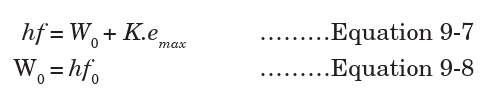
Many electrons will require more energy than the bare minimum W0
to get out of the metal, and thus the kinetic energy of such electrons will be lessthan the maximum.
Application Activity 9.1Match the mathematical symbols and their descriptions
Stopping potential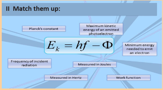
The circuit is exposed to radiations of light of frequency f and the supply of
potential difference V is connected as shown in Fig.9-15 below. The cathode
C is connected at the positive terminal of the supply and the anode P isconnected on the negative terminal of the supply.
If the circuit is exposed to radiations with the battery reversed as shown in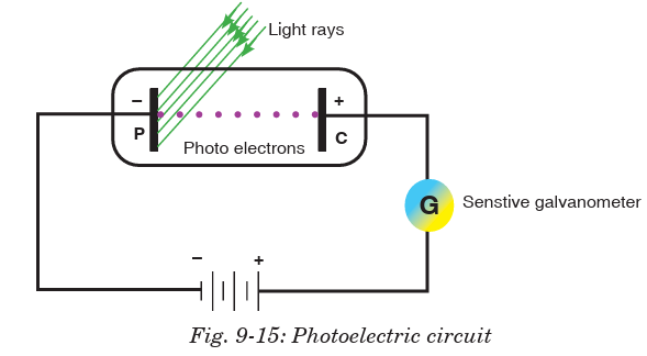
Fig. 9-16, current reduces due to the fact that all electrons emitted are not
able to reach the anode P. If this potential difference is increased until no
electron reaches the anode P, no current flows and this applied potential iscalled a stopping potential.
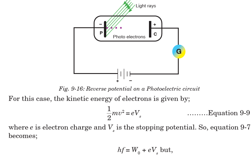
EXAMPLE 9-1
The work function for lithium is 4.6 × 10⁻¹⁹ J.
(a) Calculate the lowest frequency of light that will cause photoelectric
emission.
(b) What is the maximum energy of the electrons emitted when the light offrequency 7.3 × 10¹⁴ Hz is used?
EXAMPLE 9-2
Selenium has a work function of 5.11 eV. What frequency of light would just
eject electrons?
Solution:
When electrons are just ejected from the surface, their kinetic energy is zero.So,
Application Activity 9.2
1. Complete table 1 below.
Table 1: Applying Einstein’s photoelectric equation incalculations
2. The stopping potential when a frequency of 1.61 × 10¹⁵ Hz is
incident on a metal is 3 V.
(a) What is energy transferred by each photon?
(b) Calculate the work function of the metal.
(c) What is the maximum speed of the ejected electrons?
Aim: To know the concepts and use of photoelectric equation.
3. It is useful to observe the photoelectric effect equation represented
graphically.
(a) Express equation 9-7 in the form y = a + b, hence or otherwise,
explain how Planck’s constant can be calculated from the, graph.
(b) Express equation 9-8 in the form y = ax + b, hence or otherwise
explain how Planck’s constant can be calculated from the graph.
Aim: To graphically analyse the use of photoelectric equation.
4. In an experiment to measure the Planck’s constant, a light emitting
diode (LED) was used. Fig. 1-6 was plotted for varying energy of
the photon and frequency of the diode. Use the graph to answer thequestions that follow.
(a) Determine the slope of the line.
(b) What are the intercepts of the graph?
(c) Write down the equation of the line.
(d) What do you think is the vertical intercept?
(e) What is the value of the Planck’s constant?
(f) Write the Einstein photoelectric equation in relation to the answerof (e)
9.13 APPLICATION OF PHOTOELECTRIC EFFECT
(PHOTO EMISSIVE AND PHOTOVOLTAIC CELLS)
a) Photo electric cell
Photoelectric effect is applied in photoelectric cells or simply photocells.
These cells change light energy into electric current. Photoelectric cell
makes use of photoelectric effect and hence converts light energy into
electrical energy. The strength of the current depends on the intensity of
light falling on the cathode.
A photocell consists of an evacuated tube which is transparent to radiations
falling on it. It contains two electrodes; a semi-cylindrical cathode coated
with photosensitive material and an anode consisting of a straight wire orloop.
When radiations fall on the cathode, photoelectrons are emitted which are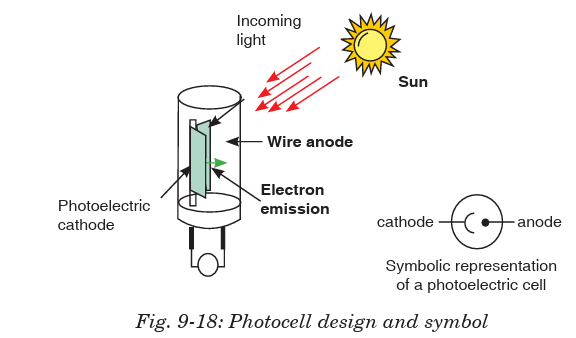
collected by the anode if it is positive with respect to the cathode. They,
then, go through the external circuit causing electric current. As intensity
of radiations increases, the number of electrons emitted by photoelectric
effect also increases. Hence current also increases.
An everyday example is a solar powered calculator and a more exoticapplication would be solar panels and others.
b) Automatic door opener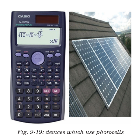
• Automatic doors operate with the help of sensors. Sensors do exactly
what they sound like they would do:
They sense things. There are many different types of sensors that cansense different types of things, such as sound, light, weight, and motion.
c) Smoke detectors
• Photoelectric Smoke Detectors. A photoelectric smoke detector is
characterized by its use of light to detect fire. The alarm detects smoke;
when smoke enters the chamber, it deflects the light-emitting diode light
from the straight path into a photo sensor in a different compartment inthe same chamber.
d) Remote control
• An Infra-Red (IR) remote (also called a transmitter) uses light to carry
signals from the remote to the device it controls. It emits pulses of
invisible infrared light that correspond to specific binary codes. Radiofrequency remotes work in a similar way.
9.14 COMPTON EFFECT
Convincing evidence that light is made up of particles (photons) and photons
have momentum can be seen when a photon with high energy hf collides
with a stationary electron.
Compton effect says that when x-rays are projected on the target, they
are scattered after hitting the target and change the direction they were
moving. This means that as a photon interacts with a free electron, the
process of photon absorption is forbidden by conservation laws, but the
photon scattering may occur. If the electron was originally at rest, then, as
a result of interaction, it acquires a certain velocity.
The energy conservation laws require that the photon energy decreases by
the value of the electron kinetic energy, which means that its frequency
must also decrease. At the same time, from the viewpoint of the wave
theory, the frequency of scattered light must coincide with the frequency ofincident light.


The photon scattering on an electron can be considered as an elastic collision
of two particles obeying the energy and momentum conservation laws
END OF UNIT ASSESSMENT
1. Describe briefly the two conflicting theories of the structure of the atom.
2. Why was the nuclear model of Rutherford accepted as correct?
3. What would have happened if neutrons had been used in Rutherford’s
experiment? Explain your answer.
4. What would have happened if aluminium had been used instead of gold
in the alpha scattering experiment? Explain your answer.
5. What three properties of the nucleus can be deduced from the Rutherford
scattering experiment? Explain your answer.
6. Monochromatic light of wavelength 560 nm incident on a metal
surface in a vacuum photocell causes a current through the cell due to
photoelectric emission from the metal cathode. The emission is stopped
by applying a positive potential of 1.30 V to the cathode with respect to
the anode. Calculate:
(a) the work function of the metal cathode in electron volts.
(b) the maximum kinetic energy of the emitted photoelectrons when
the cathode is at zero potential.
7. In a Compton scattering experiment, the wavelength of scattered
X-rays for scattering angle of 45 degree is found to be 0.024 angstrom.
(a) What is the wavelength of the incident photon?
(b) What is the percentage change in the wavelength on Compton
scattering?
8. You use 0.124-nm x-ray photons in a Compton-scattering experiment.
(a) At what angle is the wavelength of the scattered x-rays 1.0%
longer than that of the incident x-rays?
(b) At what angle is it 0.050% longer?
9. (a) What is the energy in joules and electron volts of a photon of 420
nm violet light?
(b) What is the maximum kinetic energy of electrons ejected from
calcium by 420-nm violet light, given that the binding energy (or
work function) of electrons for calcium metal is 2.71 eV?
10. An electron and a positron, initially far apart, move towards each other
with the same speed. They collide head-on, annihilating each other and
producing two photons. Find the energies, wavelengths and frequencies
of the photons if the initial kinetic energies of the electron and positron are
(a) both negligible and
(b) both 5.000 MeV. The electron rest energy is 0.511 MeV.
11. (a) Calculate the momentum of a visible photon that has a wavelength
of 500 nm.
(b) Find the velocity of an electron having the same momentum.
(c) What is the energy of the electron, and how does it compare with
the energy of the photon?
12. For an electron having a de Broglie wavelength of 0.167 nm (appropriate
for interacting with crystal lattice structures that are about this size):
(a) Calculate the electron’s velocity, assuming it is non-relativistic.
(b) Calculate the electron’s kinetic energy in eV.
UNIT SUMMARY
Structure of atom
An atom is a sphere in which positively charged particles called protons and
negatively charged particles called electrons are embedded.
Rutherford’s atomic model
Rutherford performed experiments by the scattering of alpha particles on
extremely thin gold foils. From these experiments, a new model of the atom
called Rutherford’s planetary model of the atom was born. The following
conclusions were made as regard as atomic structure:
• Most of the mass and all of the charge of an atom concentrated in a
very small region which is called atomic nucleus.
• Nucleus is positively charged and its size is of the order of 10–15 m ≈ 1
Fermi.
• In an atom, there is maximum empty space and the electrons revolve around
the nucleus in the same way as the planets revolve around the sun.
Bohr’s atomic model
Bohr’s model is based on the following postulates:
• Each electron moves in a circular orbit centered at the nucleus.
• The centripetal force needed to the electron moving in a circle is
provided by electrostatic force of attraction between the nucleus and
electrons.
• The angular momenta of electrons are whole number multiples of
• When electron moves in its allowed orbit, it doesn’t radiate energy.
The atom is then stable, such stable orbits are called stationary orbits.
• When an electron jumps from one allowed orbit to another it radiates
energy. The energy of radiation equals energy difference between levels.
hf = Ei – Ef
Energy levels and spectral lines of Hydrogen
When hydrogen atom is excited, it returns to its normal unexcited (or ground
state) state by emitting the energy it had absorbed earlier. Transition from
different orbits cause different wavelengths. These constitute spectral
series which are characteristic of the atom emitting them.
The spectral lines arising from the transition of electron forms a spectra
series. Mainly there are five series and each series is named after its
discover as Lyman series, Balmer series, Paschen series, Brackett series
and Pfund series.
Thermionic emission
Thermionic emission or discharge of electrons from heated materials, is
widely used as a source of electrons in conventional electron tubes (e.g.,
television picture tubes) in the fields of electronics and communications.
Applications of cathode rays
• Cathode ray oscilloscope
• TV tubes
Fluorescence and phosphorescence
Fluorescence is the emission of light by a substance that has absorbed light
or other electromagnetic radiation.
Phosphorescence is a specific type of photoluminescence related to
fluorescence. Unlike fluorescence, a phosphorescent material does not
immediately re-emit the radiation it absorbs.
Photoelectric emission laws’
Law 1: The photo current is directly proportional to the intensity of light
and is independent of frequency.
Law 2: The kinetic energy of the photo electrons is directly proportional to
frequency and is independent of intensity.
Law 3: Photoelectric effect does not happen when the incident frequency is
less than a minimum frequency (threshold frequency).
Law 4: There is no time lag between the incidence of photon and emission
of electrons.
Photoelectric effect
The photoelectric effect is the emission of electrons from the surface of a
metal when electromagnetic radiation (such as visible or ultraviolet light)
shines on the metal.
Factors affecting photoelectric emission
• Intensity of Light:
• Frequency:
• Number of Photoelectrons
• Kinetic Energy of Photoelectrons
Einstein’s equation photoelectric effect
Einstein suggested that the energy of the incident radiation hf was partly
used to free electrons from the binding forces on the metal and the rest
of the energy appeared as kinetic energy of the emitted electrons and his
famous equation is;
If the reverse potential difference applied on the circuit is increased until
no electron reaches the anode, no current flows and this applied potential
is called a stopping potential. This changes the Einstein’s photoelectricequation to;

Application of photoelectric effect
Photoelectric effect is applied in photoelectric cells or simply photocells.
These cells change light energy into electric current. Photoelectric cell
makes use of photoelectric effect and hence converts light energy into
electrical energy. The strength of the current depends on the intensity oflight falling on the cathode.
Compton effect
Compton effect says that when x-rays are projected on the target, they
are scattered after hitting the target and change the direction they were
moving.The Compton equation (or Compton shift) is given by;
UNIT 10: ANALOG AND DIGITAL SIGNALS
Key unit competence: Differentiate analog from digital signals.
Unit Objectives:
By the end of this unit I will be able to;
◊ Explain the transmission of information in a communication
system.
◊ Explain with examples the use of digital and analog signals ineveryday applications.
Introductory Activity
a. There has been a move by the government of Rwanda to make
her citizens to change from using analog devices to digital
devices. Analog devices transmit and receive signals in analog
form whereas digital devices transmit and receive signals
digitally.
b. a) What are different forms of signals you know that you
normally use in daily life communication?
c. b) Why do you think there is a need to change from analog to
digital signal transmission?
d. c) Mutesi communicates to her brother Ndayisenga who
studies abroad using Facebook. Is the flow of information
analog or digital? Explain your argument.
e. d) Using information gained in above questions, discuss
different signals you know.
10.1 INTRODUCTION
A signal is any kind of physical quantity that conveys information. Audible
speech is certainly a kind of signal, as it conveys the thoughts (information)
of one person to another through the physical medium of sound. Hand
gestures are signals too. This text is another kind of signal, interpreted by
your English-trained mind as information about electric circuits. In this
unit, the word signal will be used primarily in reference to an electrical
quantity of voltage or current that is used to represent or signify some other
physical quantity.
A communication system is made up of devices that employ one of two
communication methods (wireless or wired), different types of equipment
(portable radios, mobile radios, base/fixed station radios and repeaters)
accessories (examples include speaker microphones, battery eliminators and
carrying cases) and/or enhancements (encryption, digital communications,
security measures, and networking) to meet the user needs.
The most common processing of a signal in a communication system
consists of passing the signal through a linear time-invariant system. In
this context, such a system is often spoken of as a “filter”. These systems
are usually applied to reduce some undesirable components in the signal, to
compensate for some undesirable distortion of the signal, or to accentuate
some characteristic of a signal. This unit discusses digital and analog
signals and their use in modern communication.
10.2 INFORMATION TRANSMISSION
IN A COMMUNICATION SYSTEM
A communication system comprises of three sections or parts; transmitting
end, propagation medium and receiving end. This is shown on Fig. 10.1below.
The signals from information source are added to the carrier in the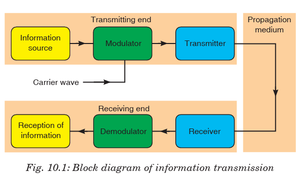
modulator. The modulated signal is sent along a channel in the propagating
medium by a transmitter. The propagation medium is a channel through
which information is transmitted. This may be a cable or free space.
At the receiving end, the receiver may have to select and perhaps amplify the
modulated signal before the demodulator extracts from it the information
signal for delivery to the receptor of information.
A propagation or transmission medium can be classified as;
Linear medium: if different waves at any particular point in medium can
be superposed.
Bounded medium: if it is finite in extent, otherwise unbound.
Uniform medium or homogeneous medium: if its physical properties
are unchanged at different points.
Isotropic medium: if its physical properties are the same in differentdirections.
10.3 COMMUNICATION TERMS AND CONCEPTS
1. Communication is the process of sharing the messages through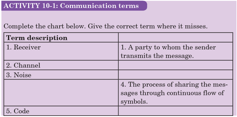
continuous flow of symbols.
2. Communicators (Sender/receiver) are the participants in communi
cation. Typically the roles reverse regularly.
3. Message is a single uninterrupted verbal or nonverbal utterance.
4. Code means a system suitable for creating/carrying messages through
a specific medium.
• encode (put into code) and
• decode (take out of code)
5. Channels (verbal, nonverbal, etc.) means the specific mechanism
(“pipeline”) used to transmit the message.
6. Mode of communication (face-to-face, television, web, phone, etc.) -
form or technology of transmission — determines kind of code used.
7. Noise - interference with message — external (physical), internal
(mental) or semantic (misunderstanding/reaction).
8. Environment (part of context) - is that which surrounds and provides
a basis for the meaning of a message:
• Physical (surroundings)
• Temporal (point in time)
• Relational (the existing relationship between communicators -
friends, strangers, etc.)
• Cultural
(language and behaviour of community and the
communicator(s) come from)
9. Feedback - checks effects of messages
• positive feedback eg. “keep doing what you’re doing”
• negative feedback eg. “change what you’re doing”.
10. Levels (contexts) of Communication
• Intrapersonal
• Interpersonal
• Public Communication
• Mass Communication (non-interactive)
• Computer Mediated Communication (interactive)
10.4 ELEMENTS OF COMMUNICATION
ACTIVITY 10-2: Elements of Communication
Aim: To find out the elementes of communication in a basic
communication model.
Carefully analyse Fig. 10.2 below and describe the elements of communication
available.
Communication is a two-way process that results in a shared meaning
or common understanding between the sender and the receiver. An
understanding of how communication works can help us to understand and
improve our communication. The basic communication model consists of
five elements of communication: the sender, receiver, message, channel and
feedback.
Sender
The sender is a party that plays the specific role of initiating communication.
To communicate effectively, the sender must use effective verbal as well as
nonverbal techniques. Such as:-
• Speaking or writing clearly.
• Organizing your points to make them easy to follow and understand.
• Maintaining eye contact.
• Using proper grammar.
• Giving accurate information.
All the above components are essential in the effectiveness of your message.
One will lose the audience if it becomes aware of obvious oversights on ones
part. The sender should have some understanding of who the receiver is, in
order to modify the message to make it more relevant.
Receiver
The receiver means the party to whom the sender transmits the message.
A receiver can be one person or an entire audience of people. In the basic
communication model, the receiver is directly connected with the speaker.
The receiver can also communicate verbally and nonverbally. The best way
to receive a message is:
• To listen carefully.
• Sitting up straight.
• Making eye contact.
• Don’t get distracted or try to do something else while you’re listening.
• Nodding and smiling as you listen.
• Demonstrate that you understand the message.
Message
The message is the most crucial element of effective communication which
includes the content a sender conveys to the receiver. A message can come
in many different forms, such as an oral presentation, a written document,
an advertisement or just a comment. In the basic communication model, the
way from one point to another represents the sender’s message travelling to
the receiver. The message isn’t necessarily what the receiver perceive it to
be. Rather, the message is what the sender intends the message to be. The
sender must not only compose the message carefully, but also evaluate the
ways in which the message can be interpreted.
Channel
The channel is a medium through which a message travels from the sender
to the receiver. The message travels from one point to another via a channel
of communication. The channel is a physical medium stands between the
sender and receiver.
Many channels or types of communication exist, such as
• The spoken word,
• Radio or television,
• An Internet site or
• Something written, like a book, letter or magazine.
Every channel of communication has its advantages and disadvantages. For
example, one disadvantage of the written word, on a computer screen or in
a book, is that the receiver cannot evaluate the tone of the message. For this
reason, effective communicators should make written word communications
clear so receivers don’t rely on a specific tone of voice to convey the message
accurately. The advantages of television as a channel for communication
include its expansive reach to a wide audience and the sender’s ability to
further manipulate the message using editing and special effects.
Feedback
This describes the receiver’s response or reaction to the sender’s message.
The receiver can transmit feedback through asking questions, making
comments or just supporting the message that was delivered. Feedback
helps the sender to determine how the receiver interpreted the messageand how it can be improved.
10.5 TYPES OF INFORMATION AND REQUIREMENTS
Constructional/creative information: This includes all information
that is used for the purpose of producing something. Before anything can
be made, the originator mobilizes his intelligence, his supply of ideas, his
know-how, and his inventiveness to encode his concept in a suitable way.
Operational information: All concepts having the purpose of maintaining
some “industry” in the widest sense of the word are included under this kind
of information. Many systems require operational information in the form
of programs for proper functioning. Examples of operational information
include:
• the operating system of a computer (eg. DOS programs),
• the program controlling a robot or a process computer,
• warning systems for airplanes and ships,
• the hormonal system of the body
Communication information: This is composed of all other kinds of
information, eg. letters, books, phone calls, radio transmissions, bird songs
and also the message of the Bible. Aspect of such information does not
include the construction of a product, neither it is involved in maintaining
some process. The goals are transmission of a message, spreading joy,amusement, instruction and personal confidences.
10.6 SIMPLEX TRANSMISSION
Simplex transmission is a single one-way base band transmission. Simplex
transmission, as the name implies, is simple. It is also called unidirectional
transmission because the signal travels in only one direction. An example
of simplex transmission is the signal sent from the TV station to the home
television.
Data in a simplex channel is always one way. Simplex channels are not
often used because it is not possible to send back error or control signals tothe transmit end.
10.7 HALF-DUPLEX COMMUNICATIONS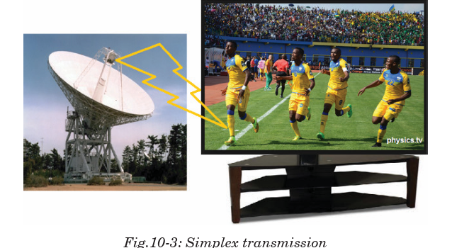
Half-duplex transmission is an improvement over simplex transmission
because the traffic can travel in both directions. Unfortunately, the road is
not wide enough to accommodate bidirectional signals simultaneously. This
means that only one side can transmit at a time. Two-way radios, such as
police or emergency communications mobile radios, work with half-duplex
transmissions. If people at both ends try to talk at the same time, none ofthe transmissions get through.
10.8 FULL-DUPLEX COMMUNICATIONS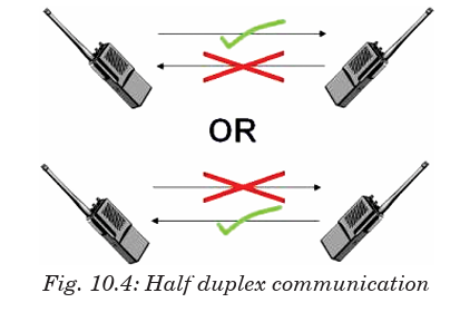
Full-duplex transmission operates like a two-way, two-lane street. Traffic
can travel in both directions at the same time.
A land-based telephone conversation is an example of full-duplex
communication. Both parties can talk at the same time, and the person
talking on the other end can still be heard by the other party while they are
talking. Although when both parties are talking at the same time, it might
be difficult to understand what is being said.
Full-duplex networking technology increases performance because data
can be sent and received at the same time. Digital subscriber line (DSL),
two-way cable modem, and other broadband technologies operate in
full-duplex mode. With DSL, for example, users can download data to theircomputer at the same time they are sending a voice message over the line.
10.9 BANDWIDTH AND SIGNAL FREQUENCY
Frequency is a parameter that determines how often the sinusoidal signal
goes through a cycle. It is usually represented with the symbol f, and it hasthe unit hertz.
Where T is a periodic time and is measured in seconds.
The bandwidth of a composite signal is the difference between the highest
and the lowest frequencies contained in that signal. It is typically measured
in hertz, and may sometimes refer to passband bandwidth or basebandbandwidth, depending on context.
10.10 ANALOG SIGNAL SYSTEM
A system is a physical set of components that take a signal and produces a
signal. In terms of engineering, the input is generally some electrical signal
and the output is another electrical signal.
Analog systems operate with values that vary continuously and have no
abrupt transitions between levels. For a long time, almost all electronic
systems were analog, as most things we measure in nature are analog. For
example, your voice is analogous; it contains an infinite number of levels
and frequencies. Therefore, if you wanted a circuit to amplify your voice, an
analog circuit seems a likely choice.
In Rwanda recently analog systems were replaced by digital systems that
provide greater capacity of data transfer and increased reliability and
security.
Example of an analog electronic system
A public address system
A public address system (PA system) is an electronic sound amplification
and distribution system with a microphone, amplifier and loudspeakers, used
to allow a person to address a large public, for example for announcementsof movements at large and noisy air and rail terminals or a sports stadium.
10.11 ANALOG SIGNALS
Analog signal is a continuous signal that contains time varying quantities.
An analog signal is a continuous wave denoted by a sine wave and may
vary in signal strength (amplitude) or frequency (time). The sine wave’s
amplitude value can be seen as the higher and lower points of the wave,
while the frequency (time) value is measured in the sine wave’s physicallength from left to right.
Analog signal can be used to measure changes in physical phenomenon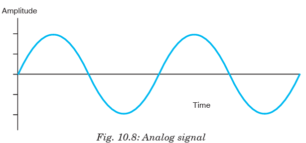
such as light, sound, pressure, or temperature. For instance, microphone
can convert sound waves into analog signal. Even in digital devices, there
is typically some analog component that is used to take in information from
the external world which will then get translated into digital form –using
analog to digital converter.
10.12 ADVANTAGES AND DISADVANTAGES OF
ANALOG SIGNALS
Advantages
• Uses less bandwidth than digital sounds.
• More accurate representation of sound.
• It is the natural form of sound.
• Because of editing limitations, there is little someone can do to tinker
with the sound, so what you are hearing is the original sound.
Disadvantages
• There are limitations in editing.
• Recording analog sound on tape is expensive.
• It is harder to synchronize analogous sound.
• Quality is easily lost if the tape becomes ruined.
• A tape must always be wound and rewound in order to listen to specific
part of sound which can damage it.
• Analog is susceptible to clipping where the highest and lowest notes of
a sound are cut out during recording.
10.13 DIGITAL SIGNALS
In electronic signal and information processing and transmission, digital
technology is increasingly being used because, in various applications, digital
signal transmission has many advantages over analog signal transmission.
Numerous and very successful applications of digital technology include the
continuously growing number of PC’s, the communication network ISDN as
well as the increasing use of digital control stations (Direct Digital Control:
DDC).
Unlike analog technology which uses continuous signals, digital technology
encodes the information into discrete signal states. When only two states
are assigned per digital signal, these signals are termed binary signals.One single binary digit is termed a bit - a contraction for binary digit.
10.14. ADVANTAGES OF DIGITAL TECHNOLOGY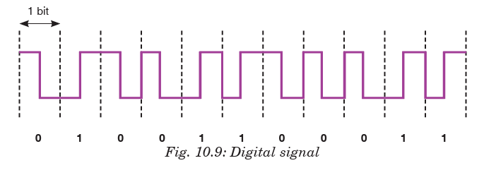
•More capacity from the same number of frequencies; that is, they
provide superior Spectral Efficiency. This is a result of the modulation
methods used, and the fact that, in many cases more than one
‘conversation’ can be accommodated within a single radio channel.
• Consistent voice clarity at low received signal levels near the
edge of coverage. The general consensus is that digital radios provide
better audio quality than analog ones. With analog FM radios, the audio
quality steadily declines as the received signal strength gets weaker.
Digital radios however, will have a consistent audio quality throughout
the full service area. The edges of the coverage area in a digital radio
system are similar to those experienced with cellular telephones.
• Data is defined in the standard. This means data implementations
are no longer proprietary, there are a wide variety of data mechanisms
and inter operability can extend into the data domain. With the accepted
increase of efficiency by using data communications over voice, this
will further increase the usability and effectiveness of digital radio
systems.
• Secure transmissions: In digital technologies, data and voice can
be secured using encryption without impacting voice quality usingindustry standard encryption techniques.
10.15 COMPARING DIGITAL AND ANALOG SIGNALS
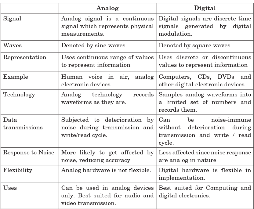

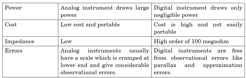
Principle of digital signal systems
A digital signal refers to an electrical signal that is converted into a pattern
of bits. Unlike an analog signal, which is a continuous signal that contains
time-varying quantities, a digital signal has a discrete value at each sampling
point. The precision of the signal is determined by how many samples are
recorded per unit of time. For example, the illustration of fig below shows
an analog pattern (represented as the curve) alongside a digital pattern(represented as the discrete lines).
Analog pattern alongside digital pattern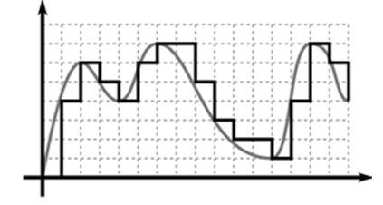
A digital signal is easily represented by a computer because each sample
can be defined with a series of bits that are either in the state 1 (on) or 0 (off).
Digital signals can be compressed and can include additional information
for error correction. A signal in which the original information is converted
into a string of bits before being transmitted. A radio signal, for example,
will be either on or off. Digital signals can be sent for long distances and
suffer less interference than analog signals.
Boolean functions may be practically implemented by using electronic
gates. The following points are important to understand.
• Electronic gates require a power supply.
• Gate INPUTS are driven by voltages having two nominal values, e.g. 0 V
and 5 V representing logic 0 and logic 1 respectively.
• The OUTPUT of a gate provides two nominal values of voltage only, e.g. 0
V and 5 V representing logic 0 and logic 1 respectively. In general, there
is only one output to a logic gate except in some special cases.
• There is always a time delay between an input being applied and theoutput responding.
Application Activity
Question on digital and analogue signal.
1. The two basic types of signals are analog and:
A. Digilog
B. Digital
C. Vetilog
D. Sine wave
2. Which of the following characterizes an analog quantity?
A. Discrete levels represent changes in a quantity.
B. Its values follow a logarithmic response curve.
C. It can be described with a finite number of steps.
D. It has a continuous set of values over a given range.
3. Which type of signal is represented by discrete values?
A. Noisy signal
B. Nonlinear
C. Analog
D. Digital
4. A data conversion system may be used to interface a digital computer system to:
A. An analog output device
B. A digital output device
C. An analog input deviceD. A digital printer
10.16 LOGIC GATES
There are three basic logic gates each of which performs a basic logic
function. They are called NOT, AND and OR. All other logic functions can
ultimately be derived from combinations of these three. For each of the
three basic logic gates a summary is given including the logic symbol, thecorresponding truth table and the Boolean expression.
The AND gate is an electronic circuit that gives a high output (1) only if all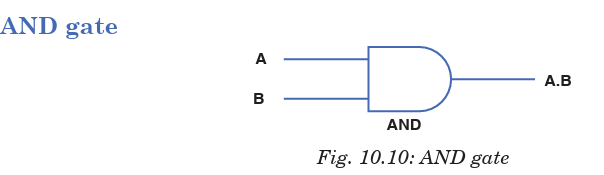
its inputs are high. A dot (.) is used to show the AND operation i.e. A.B. Itcan also be written as AB.
The OR gate is an electronic circuit that gives a high output (1) if one or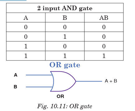
more of its inputs are high. A plus (+) is used to show the OR operation.

The NOT gate is an electronic circuit that produces an inverted version of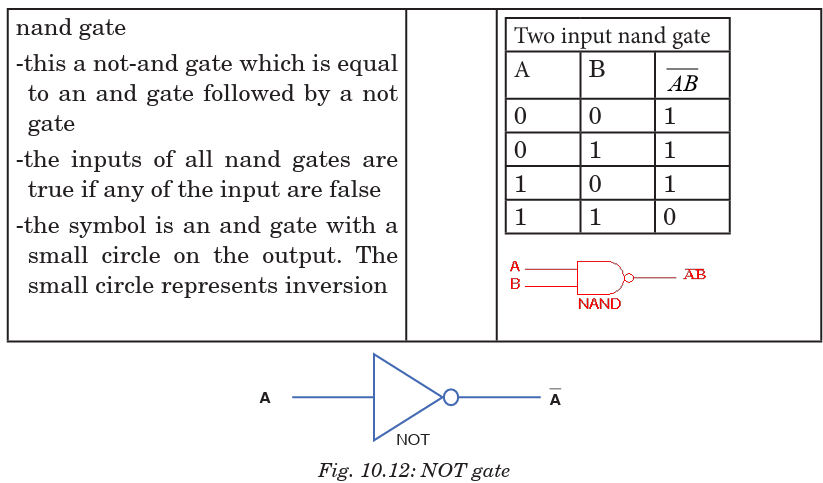
the input at its output. It is also known as an inverter. If the input variable
is A, the inverted output is known as NOT A. This is also shown as A′, or A.as shown at the outputs.

Another useful gate used in the digital logic circuits is EX–OR gate.
The ‘Exclusive-OR’ gate is a circuit which will give a high output if either,
but not both, of its two inputs are high. An encircled plus sign (⊕) is usedto show the EX–OR operation.
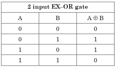
EXAMPLE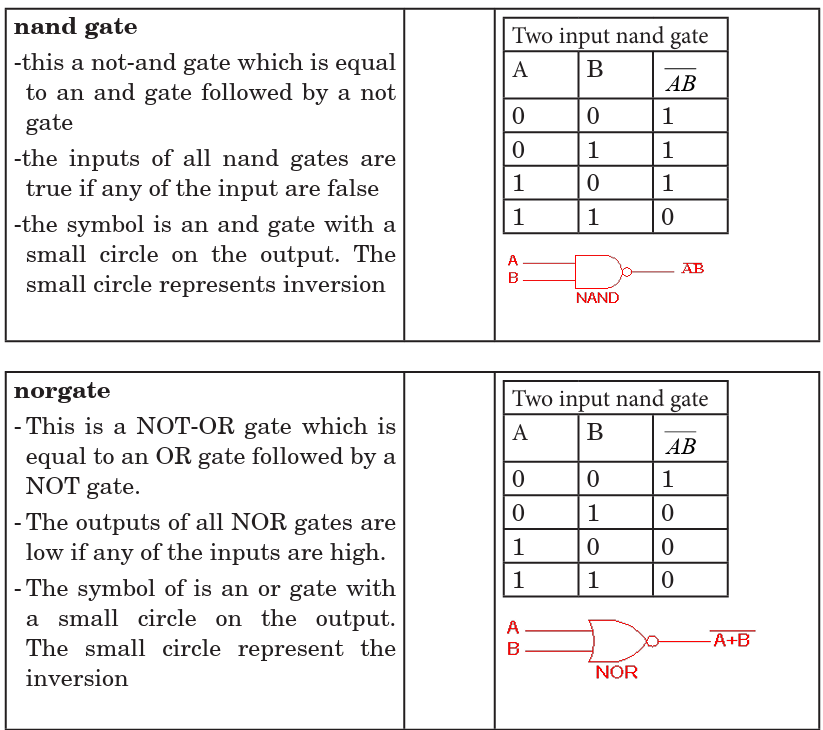
Construct a truth table of the following logic circuit
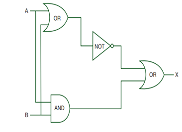
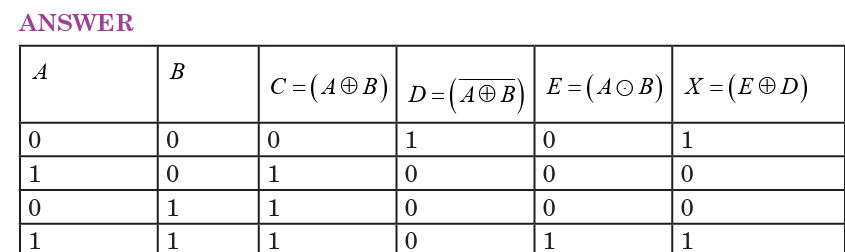
Application Activity
1. Produce a truth table from the following logic circuit (network)
2. For the logic circuits below produce the truth tables. Rember, if there are 2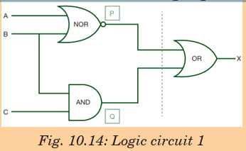
inputs then there will be 4 outputs; if there are 3 inputs then there will be 8
possible outputs. Use the ida shown in the logic circuits discussed in section10.6.
END OF UNIT ASSESSMENT
1. There has been a move to advise people to change from using analog
systems to start using digital systems especially here in Rwanda. Do
you support this move? If yes, why? If no why not?2. Produce a truth table from the following logic circuit (network).
3. For the logic circuits below produce the truth tables. Remember, if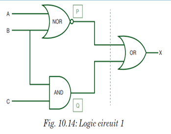
there are 2 inputs then there will be 4 outputs; if there are 3 inputs
then there will be 8 possible outputs. Use the idea shown in the logiccircuits discussed in section 10.6.
UNIT SUMMARY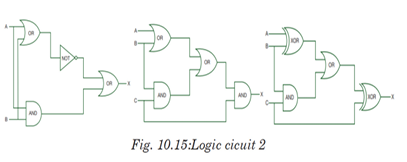
Information transmission in a communication system
The signals from information source are added to the carrier in the
modulator. The modulated signal is sent along a channel in the propagating
medium by a transmitter. The propagation medium is a channel through
which information is transmitted. This may be a cable or a free space.
Communication Terms and Concepts
•Communication
• Communicator
• Message
• Medium
• Noise
• Environment
• Feedback
• Levels
Elements of communication
• Sender
• Receiver
• Message
• Channel
• Feedback
Types of information and requirements
•Constructional/creative information
• Operational information
• Communicational information
Simplex transmission
Simplex transmission is a single one-way base band transmission. Simplex
channels are not often used because it is not possible to send back error or
control signals to the transmit end.
Half-duplex communications
Half-duplex transmission is an improvement over simplex because the
traffic can travel in both directions. Full-duplex networking technology
increases performance because data can be sent and received at the same
time.
Bandwidth and signal Frequency
The bandwidth of a composite signal is the difference between the highest
and the lowest frequencies contained in that signal.Mathematically, the bandwidth is given by;
• Medium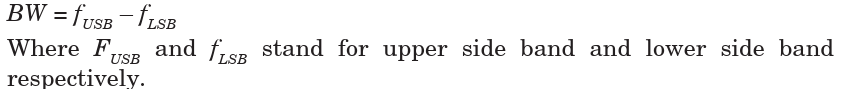
• Noise
• Environment
• Feedback
• Levels
Elements of communication
Analogue signal system
Analogue systems operate with values that vary continuously and have no
abrupt transitions between levels.
Analog signals
Analog signal is a continuous signal that contains time varying quantities.
An analog signal is a continuous wave denoted by a sine wave and may vary
in signal strength (amplitude) or frequency (time).
Digital signals
Unlike analog technology which uses continuous signals, digital technology
encodes the information into discrete signal states. Numerous and very
successful applications of digital technology include the continuously
growing number of PC’s, the communication net work ISDN as well as the
increasing use of digital control stations (Direct Digital Control: DDC).
Advantages of digital technology
• More capacity from the same number of frequencies.
• Consistent voice clarity at low received signal levels near the edge of
coverage.
• Data is defined in the standard.
• Secure transmissions.
Logic gates
There are three basic logic gates each of which performs a basic logic
function, they are called NOT, AND and OR. All other logic functions canultimately be derived from combinations of these three.
UNIT 11: MOBILE PHONE AND RADIO COMMUNICATION
Key unit competence: By the end of the unit I should be able to
distinguish mobile phone system from radio system of communication.
Unit Objectives:
By the end of this unit I will be able to;
◊ explain the concept and principles of cellular radio network.
◊ explain the need for cellular system in modern mobilecommunication.
Introductory Activity
The figure below shows how network for a certain telecommunications
company in Rwanda. Study it carefully and answer the followingquestions.
Network transmission
a. How many cells can you see in the figure above?
b. Identify different masts shown on the figure.
c. In regard to the figure, what is the importance of masts in
those different cells?
d. Why do you think in transmission of network, the targeted
area is divided into small portions?
e. Compare the number of cells that should be allocated for urbanareas to those for rural areas.
11.0 INTRODUCTION
The communication is the way of expressing our thoughts. In other words,
communication means sending or receiving message from one end to
other. We can express our feelings to others by speaking, writing or silent
indications. All living beings communicate to each other in different ways.
They have different types of voices and they understand meaning of voice
of their species. Human has also developed his dialect to communicate with
others. We learn different languages to understand meaning of other’s
dialects.
Devices used to talk, or to send message one end to other, or from one person
to other are called means of communication. Means of Communication are
the most necessary part of modern lifestyle. In modern age, there are many
types of means of communications like newspaper, Telephone, Mobile, TV,
Internet etc. They play very important role in our daily life activities.
This concept is closely related to the concepts of blood circulation (in Biologyand Medicine), transport networks, transmission of information etc.
11.1 CONCEPTS OF TRANSMISSION SYSTEM
In telecommunication, a communication system is a collection of individual
communication networks, transmission systems, relay stations tributary
stations and Data Terminal Equipment (DTE) usually capable ofinterconnection and interoperation to form an integrated whole.
In the transmission section, first of all, the source generated information is
fed to the input transducer, which converts energy of one form to another
form, usually in electrical form. This electrical signal or base band signal is
sent to the transmitter.
Transmitter:
Transmitter modifies the information signal for efficient transmission.
It modulates the information signal with a high frequency carrier. After
processing the signal transmitter transmits the signal, through channel to
the receiver.
Channel:
Channel, media or path implies the medium through which the message
travels from the transmitter to the receiver. A channel acts partly as a filter
to attenuate the signal and distorts its waveform. The signal attenuation
increases with the length of the channel. There are different types of
channels for different communication systems, such as wire, coaxial cable,
wave-guide, optical fiber or radio link through which transmitter output is
sent.
Receiver:
Receiver reprocesses the signal received from the channel by undoing the
signal modifications made at the transmitter and the channel. The receiver
output is fed to the output transducer, which converts the electrical signal
to its original form. By this way, the signal reached to its destination, towhich the message is communicated.
Digital communication:
Digital communication system exchange (both transmit and receive)
information to /from digital sources.
A digital (information) source produces a finite set of possible messages.
Typewriter is a good example of a digital source. There is a finite no. of
characters that can be emitted by this source.
Analog communication:
Analog communication system exchange (both transmit and receive)
information to /from analog sources. A microphone is a good example of an
analog source. An analog information source produces messages that are
defined on a continuum.
Why do we use digital not analog?
Digital communication has a number of advantages:
• Relatively inexpensive digital circuits may be used.
• Digital systems are relatively easy to design and can be fabricated on
IC chips.
• Information storage is easy.
• Operation can be programmable to update with newly upcoming
technologies.
• Privacy is preserved by using data encryption.
• Greater dynamic range is possible.
• Data from voice, video and data sources may be merged and transmitted
over a common digital transmission system. i.e. it is easy to multiplex
several digital signals.
• In long distance communication system, noise does not accumulate
from repeater to repeater.
• Error detection and correction schemes can be employed by using
coding techniques.
Limitations of Digital communication system
• Generally, more bandwidth is required than that for analog system.
• Synchronization is required, which calls for more sophisticated device
and costs more.
A/D converter
We use analog to digital converter, to convert analog signals to digital
signals.
A/D conversion has three steps:
(a) Sampling
In this process, Continuous-time signal is converted to Discrete-time signal
obtained by taking samples of the continuous-time signal at discrete-time
instants.
(b) Quantization
In this process, a Discrete-time Continuous- valued signal is converted
into a Discrete-time Discrete-valued (digital) signal. The sampled signal is
rounding off to the fourth nearest value which is permitted for transmission
by the system. The process of rounding off is called Quantization, while the
possible levels permitted for transmission are called Quantizing levels.
(c) Coding
In the coding process, each discrete value is represented by 8-bit binary
sequence e.g. 10010101. It consists of combinations of 0 and 1.
11.2 PRINCIPLE OF CELLULAR RADIO
The cellular concept was a major breakthrough in solving the problem of
spectral congestion and user capacity. It offered very high capacity output
in a limited spectrum allocation without any major technological changes.
The cellular concept is a system-level idea which calls for replacing a single,
high power transmitter (large cell) with many low power transmitters (small
cells), each providing coverage to only a small portion of the service area.
Each base station is allocated a portion of the total number of channels
available to the entire system, and nearby base stations are assigned
different groups of channels so that all the available channels are assigned
a relatively small number of neighbouring base stations. Neighbouring base
stations are assigned different groups of channels so that the interference
between base stations (and the mobile users under their control) is
minimized.
By systematically spacing base stations and their channel groups throughout
a market, the available channels are distributed throughout the geographic
region and may be reused as many times as necessary so long as the
interference between co-channel stations is kept below acceptable levels.
11.3 STRUCTURE OF CELLULAR NETWORK
An overall cellular network contains a number of different elements from
the base transceiver station (BTS) itself with its antenna back through
a base station controller (BSC), and a mobile switching centre (MSC)
to the location registers (HLR and VLR) and the link to the public switched
telephone network (PSTN).
Of the units within the cellular network, the BTS provides the direct
communication with the mobile phones. There may be a small number of
base stations linked to a base station controller. This unit acts as a small
centre to route calls to the required base station, and it also makes some
decisions about which base station is the best suited for a particular call.
The links between the BTS and the BSC may use either land lines of even
microwave links. Often the BTS antenna towers also support a small
microwave dish antenna used for the link to the BSC. The BSC is often
co-located with a BTS.
The BSC interfaces with the mobile switching centre. This makes more
widespread choices about the routing of calls and interfaces to the land linebased PSTN as well as the location registers.
11.4 PRINCIPLE OF CELLULAR NETWORK
Increase in demand and the poor quality of existing service led mobile
service providers to research ways to improve the quality of service and
to support more users in their systems. Because the amount of frequency
spectrum available for mobile cellular use was limited, efficient use of the
required frequencies was needed for mobile cellular coverage. In modern
cellular telephony, rural and urban regions are divided into areas accordingto specific provisioning guidelines.
Deployment parameters, such as amount of cell-splitting and cell sizes,
are determined by engineers experienced in cellular system architecture.
Provisioning for each region is planned according to an engineering plan
that includes cells, clusters, frequency reuse, and handovers.
Cells
A cell is the basic geographic unit of a cellular system. The term cellular
comes from the honeycomb shape of the areas into which a coverage region
is divided. Cells are base stations transmitting over small geographic areas
that are represented as hexagons. Each cell size varies depending on the
landscape. Because of constraints imposed by natural terrain and man
made structures, the true shape of cells is not a perfect hexagon
Clusters
A cluster is a group of cells. No channels are reused within a cluster.
Fig.11-2 illustrates a seven-cell cluster. In clustering, all the available
frequencies are used once and only once. As shown on Fig.11-3, each cell
has a base station and any mobile user moving remains connected due tohand-offs between the stations.
Frequency Reuse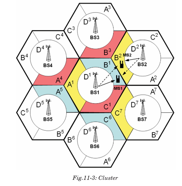
Because only a small number of radio channel frequencies were available
for mobile systems, engineers had to find a way to reuse radio channels in
order to carry more than one conversation at a time. The solution was called
frequency planning or frequency reuse. Frequency reuse was implemented
by restructuring the mobile telephone system architecture into the cellular
concept.
The concept of frequency reuse is based on assigning to each cell a group of
radio channels used within a small geographic area. Cells are assigned a
group of channels that is completely different from neighbouring cells. The
coverage area of cells are called the footprint. This footprint is limited by a
boundary so that the same group of channels can be used in different cells
that are far enough away from each other so that their frequencies do notinterfere.
Cells with the same number have the same set of frequencies. Here, because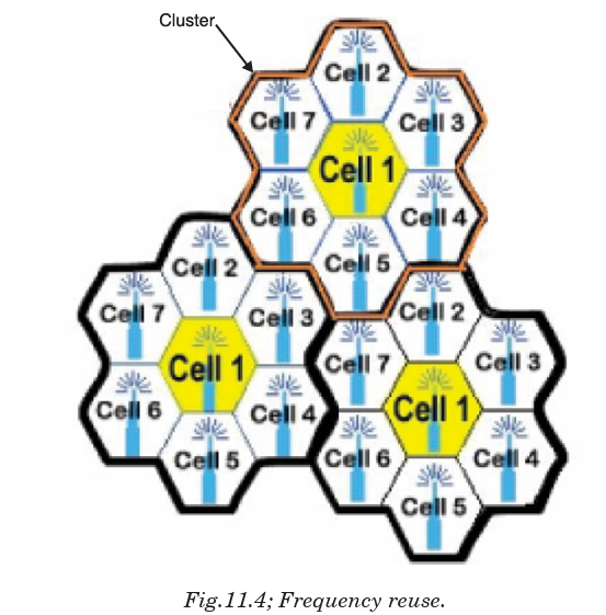
the number of available frequencies is 7, the frequency reuse factor is 1/7.
That is, each cell is using 1/7 of available cellular channels.
Cell Splitting
Unfortunately, economic considerations made the concept of creating fullsystems with many small areas impractical. To overcome this difficulty,
system operators developed the idea of cell splitting. As a service area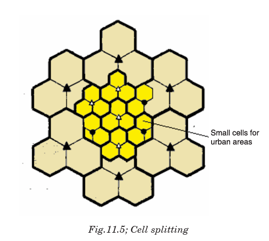
becomes full of users, this approach is used to split a single area into
smaller ones. In this way, urban centers can be split into as many areas
as necessary in order to provide acceptable service levels in heavy-traffic
regions, while larger, less expensive cells can be used to cover remote rural
regions.
Handoff
The final obstacle in the development of the cellular network involved the
problem created when a mobile subscriber travelled from one cell to another
during a call. As adjacent areas do not use the same radio channels, a call
must either be dropped or transferred from one radio channel to another
when a user crosses the line between adjacent cells. Because dropping the
call is unacceptable, the process of handoff was created. Handoff occurs
when the mobile telephone network automatically transfers a call fromradio channel to radio channel as a mobile crosses adjacent cells.
During a call, two parties are on one voice channel. When the mobile unit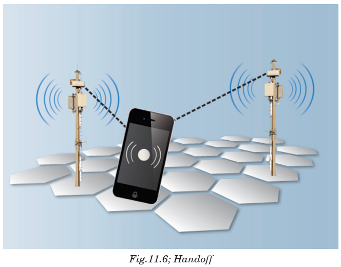
moves out of the coverage area of a given cell site, the reception becomes
weak. At this point, the cell site in use requests a handoff. The system
switches the call to a stronger-frequency channel in a new site without
interrupting the call or alerting the user. The call continues as long as the
user is talking, and the user does not notice the handoff at all.
11.5 MOBILE COMMUNICATION SYSTEMS
Mobile communication systems have become one of the hottest areas in the
field of telecommunications and it is predicted that within the next decade,
a considerable number of connections will become partially or completely
wireless. Rapid development of the Internet with its new services and
applications has created fresh challenges for the further development of
mobile communication systems.
We can say that mobile communication system is a high capacity
communication system arranged to establish and maintain continuity of
communication paths to mobile stations passing from the coverage of one
radio transmitter into the coverage of another radio transmitter. A control
center determines mobile station locations and enables a switching center
to control dual access trunk circuitry to transfer an existing mobile station
communication path from a formerly occupied cell to a new cell location.
The switching center subsequently enables the dual access trunk to releasethe call connection to the formerly occupied cell.
ACTIVITY 11-1: The Concept of Communication
Aim: this activity aim at understanding the concept of
communication.
a) The figure below shows the Amahoro village. Explain all the possibleways of communication according to the infrastructure shown.
b) Use the equipment below and create 2 communication stories. You
must use at least 4 equipments.
11.6 RADIO TRANSMISSION (AM, FM, PM)
Application Activity
Radio receiver
While listening to radio on one of the evening, Mukagatsinzi heard
that the tuned channel was on FM at 100.7 MHz But her radio works
efficiently when she pulls up the antenna.
f. What do you think is the significance of the antenna on her
radio?
g. Hoping you have ever used/played a radio. Where do you think
the information/sound from the radio come from?
h. Explain the mode of transmission of information as suggested
in b) above to the receiving radio.
i. While going to sleep, her radio fell down and the speaker got
problems. Do you think she was able to listen to late night
programs on the same channel?
j. As indicated on the radio, what does FM, MW, and SW mean?
Modulation is a technique used for encoding information into a RF channel.
Typically the process of modulation combines an information signal with
a carrier signal to create a new composite signal that can be transmitted
over a wireless link. In theory, a message signal can be directly sent into
space to a receiver by simply powering an antenna with the message signal.
However, message signals typically don’t have a high enough bandwidth
to make efficient direct propagation. In order to efficiently transmit data,the lower frequency data must be modulated onto a higher frequency wave.
The high frequency wave acts as a carrier that transmits the data through
space to the receiver where the composite wave is demodulated and the
data is recovered. There are a few general types of modulation; Frequency
Modulation (FM), Phase Modulation (PM) and Amplitude modulation (AM).
Frequency modulation (FM)
This is a kind of modulation which is used in every high broadcasts. The
frequency of the carrier is altered at a rate equal to the frequency of theaudio frequency but the amplitude remains constant.
Frequency modulation is widely used for FM radio broadcasting. It is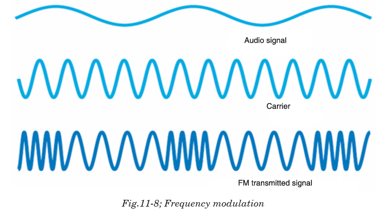
also used in telemetry, radar, seismic prospecting monitoring newborns
(for seizures via Electroencephalography), two-way radio systems, music
synthesis, magnetic tape-recording systems and some video-transmission
systems. In radio transmission, an advantage of frequency modulation is
that it has a larger signal-to-noise ratio and therefore rejects radio frequency
interference better than an equal power amplitude modulation (AM) signal.For this reason, most music is broadcast over FM radio.
Amplitude modulation (AM)
In amplitude modulation, the information signal is used to vary the
amplitude of the carrier so that it follows the wave shape of information
signal. Here, before the information is transmitted, it is first mixed to a
carrier signal so that it can be transmitted over a long distance with lowattenuation.
The modulated signal contains other frequencies called side frequencies
which are created on either sides of the carrier. If the carrier frequency is
fc and modulated frequency is fm
, two new frequencies are fc – fm and fc + fm.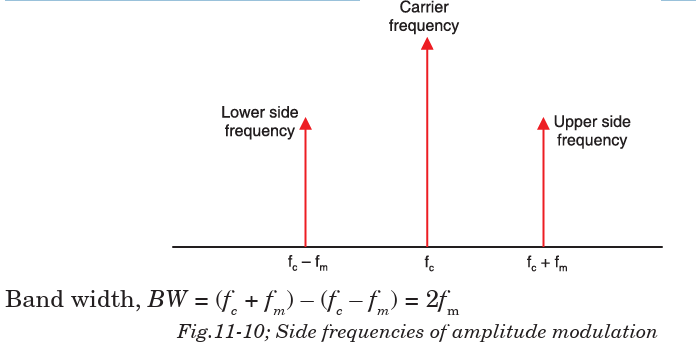
Phase modulation (PM)
Phase modulation is a form of modulation that encodes information asvariations in the instantaneous phase of the carrier wave. It is widely
used for transmitting radio waves and is an integral part of many digital
transmission coding schemes that underlie a wide range of technologies
like WiFi, GSM and satellite television. In this type of modulation, the
amplitude and frequency of the carrier signal remains unchanged after
PM. The modulating signal is mapped to the carrier signal in the form of
variations in the instantaneous phase of the carrier signal.
Phase modulation is closely related to frequency modulation and is oftenused as intermediate step to achieve FM.
11.7 POST, TELEGRAPH AND TELEPHONE (PTT)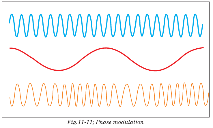
A postal, telegraph and telephone service (or PTT) is a government
agency responsible for postal mail, telegraph and telephone services. Such
monopolies existed in many countries, though not in North America or
Japan. Many PTTs have been partially or completely privatized in recent
years. In some of those privatizations, the PTT was renamed completely,
whereas in others, the name of the privatized corporation has been only
slightly modified.
Postal services transport mail and small packages to destinations around
the world, and they are mostly public corporations. However, there has
been increased privatization of postal operators in the past 20 years, and
government restrictions on private postal services have eased. Postal
authorities are often also involved in telecommunications, logistics, financial
services and other business areas.
Rwanda is part of the Universal Postal Union, which recommends a
maximum of 9,000 people per one post office branch. The ‘iPosita Rwanda
is the company responsible for postal service in Rwanda.
A telegraph is a communication system in which information is transmitted
over a wire through a series of electrical current pulses, usually in the form
of Morse code. The basic components include a source of direct current, a
length of wire or cable, and a current-indicating device such as a relay,buzzer or light bulb.
Telephony is the technology associated with the electronic transmission
of voice, fax, or other information between distant parties using systems
historically associated with the telephone, a handheld device containing
both a speaker or transmitter and a receiver. With the arrival of computers
and the transmission of digital information over telephone systems and
the use of radio to transmit telephone signals, the distinction between
telephony and telecommunication has become difficult.
Aim: The purpose of this activity is to give the real structure ofcommunication network and the terms used.
Procedure: Use the following clues to fill the puzzle. The sentences to
help in filling the puzzle are also given below.
ANTENNA, CAMERA , CELLULAR, FAX, FILM, HEADPHONE,
KEYBOARD, LENS, MICROPHONE, PEN, PLUG, PRINTER, RADIO,
SATELLITE, SPEAKER, TELEPHONE, TELEVISION, TRIPOD,
TURNTABLE, VIDEO.
ACROSS:
4. I’m out of my office. I’m calling you on my cellular telephone.
8. The signal bounces off a satellite high up in outer space.
10. The …………… needs a new link cartridge.
13. The …………… makes his voice sound much louder.
16. The sound from the radio can out of a …………….
17. I have the car ………………. tuned to my favorite station.
18. I used a …….. to write a letter.
20. I type on my computer ………………
ACTIVITY 11-2: Structure of Communication Networks
DOWN:
1. You have to ……….. it in before it will work.
2. I bought a new …….. for my camera.
3. On the airplane everyone listened to the movie through …………
4. The ….. on my car helps distant radio stations come in more clearly.
5. My favorite ………. Channel is the one that carries Oprah.
6. What is your ………… number? I’ll call you tomorrow.
7. That ……… was directed by Steven Spielberg
8. You play vinyl records on a ………….
9. He took photographs of their vacation with his digital ………….
10. The band shot a ……….. of their latest song.
11 …………… is short for facsimile.
12. The camera was perched on a ……………
END OF UNIT ASSESSMENT
1. What do you understand by the term Modulation.
2. Explain the meaning of Amplitude Modulation.
3. Explain the different types of analog modulation.
4. In modern system, Modulation very important while transmitting signals.
Discuss why modulation should be done in transmission of signals and
information.
5. Discuss the objectives that are achieved when modulation is done.
6. Explain the meaning of frequency modulation.
UNIT SUMMARY
Concepts of transmission system
In telecommunication, a communication system is a collection of
individual communication networks, transmission systems, relay stations,
tributary stations, and data terminal equipment (DTE) usually capable of
interconnection and interoperation to form an integrated whole.
Principle of cellular radio
The cellular concept is a major breakthrough in solving the problem of
spectral congestion and user capacity. It involves dividing the area into
small parts called cells. The neighbouring base stations are assigned
different groups of channels so that the interference between base stations
(and the mobile users under their control) is minimized. It offers very high
capacity in a limited spectrum allocation without any major technological
changes.
Structure of cellular network
An overall cellular network contains a number of different elements from
the base transceiver station (BTS) itself with its antenna back through
a base station controller (BSC) and a mobile switching centre (MSC) to
the location registers (HLR and VLR) and the link to the public switched
telephone network (PSTN).
The BSC is often co-located with a BTS. The BSC interfaces with the mobile
switching centre. This makes more widespread choices about the routing
of calls and interfaces to the land line based PSTN as well as the HLR and
VLR.
Principle of cellular network
Because the amount of frequency spectrum available for mobile cellular use
was limited, efficient use of the required frequencies was needed for mobile
cellular coverage. In modern cellular telephony, rural and urban regions
are divided into areas according to specific provisioning guidelines.
Modulation techniques
Modulation is a technique used for encoding information into a RF channel.
There are a few general types of modulation; Frequency Modulation (FM),Phase Modulation (PM), and Amplitude modulation (AM).
UNIT 12: RELATIVITY CONCEPTS AND POSTULATES OF SPECIAL RELATIVITY
Key unit competence: By the end of the unit, I be able to analyse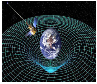
Relativity Concepts and postulates of special relativity.
Unit Objectives:
By the end of this unit I will be able to;
◊ Explain the concept of general and special relativity.◊ Explain the concept of the frames of reference and apply it in other theories.
Introductory Activity
On the first day of traveling in a car, Shyaka observed trees, stones,
mountains and all stationary saw them moving in the direction where
the car was coming from.
a. Were the trees, stones and mountains actually moving?
b. If No, why did Shakya see them moving?
c. As Shyaka and friends in the same car tried to take over another
speeding vehicle that was travelling in the same direction with
the same speed, Shyaka observed that the car they were trying
to overtake seemed to be stationary. Explain the cause of this
effect.
12.0 INTRODUCTION
The general theory of relativity developed in the early 20th century, originally
attempted to account for certain anomalies in the concept of relative motion.
But it has developed into one of the most important basic concepts in
physical science. The theory of relativity, developed primarily by German
American physicist Albert Einstein, is the basis for later demonstration by
physicists of the essential unity of matter and energy of space and time of
gravity and acceleration.
12.1 DEFINITION OF RELATIVITY
This is a theory developed by Albert Einstein which says that anything
except light moving with respect to the time and space depends on the
position and movement of the observer. Einstein’s special theory of relativity
(special relativity) is all about what’s relative and what’s absolute about
time, space and motion.
The theory states that the laws of motion are the same for all inertial
(non-accelerating) frames of reference and that the speed of light (in a
vacuum) is the same for all inertial reference frames. This leads to the
equivalence of mass and energy, time dilation, and length contraction.
Special relativity requires us to think of space and time as inextricably
linked. All our measurements of distance and time depend on the motion
of the observer. The effects of time dilation and length contraction are only
observed at very high speeds (close to the speed of light).
Thus, in Physics, Relativity refers to Einstein’s theory that time and space
are not absolute. OR, Anything except light moves with respect to time and
space depends on the position and movement of someone who is watching.
12.2 CONCEPT OF SPACE, TIME AND MASS
Time Dilation
Time dilation is the phenomenon where two objects, moving with respect
to each other (or even just a different intensity of gravitational field from
each other) experience different rates of time flow.
Time dilation becomes most apparent when one of the objects is moving at
nearly the speed of light, but it manifests at even slower speeds. Here are
just a few ways we know time dilation actually takes place:
• Clocks in airplanes click at different rates from clocks on the ground.
• Putting a clock on a mountain (thus elevating it, but keeping it
stationary relative to the ground-based clock) results in slightly
different rates.
• The Global Positioning System (GPS) has to adjust for time dilation.
Ground-based devices have to communicate with satellites. To work,
they have to be programmed to compensate for the time differences
based on their speeds and gravitational influences.
Let’s construct a light beam clock. It consists of two mirrors, one at a
distance D above the other. At t = 0, we launch a photon of light upwards
from the bottom of the mirror. It reflects from the top mirror and returns toits starting position, use c as the speed of the photon;
This is the time for one tick of our clock. At least this shows how it seems
to someone at rest with respect to the clock. But how does this appear to an
observer watching us and our clock moves by at constant velocity v? Thisobserver sees the events as pictured below.

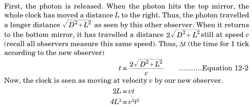
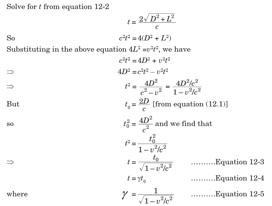

Length Contraction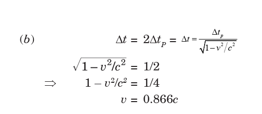
If we turn our light beam clock to face in the direction of motion, time
dilation implies length contraction. If the observer at rest with respect
to the clock (now a ruler) says it has proper length L0
, then an observer
on the earth watching him and his clock/ruler by velocity v sees the ruler
having length L. Objects look shorter (they are contracted) in the directionof motion.
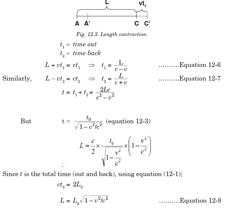
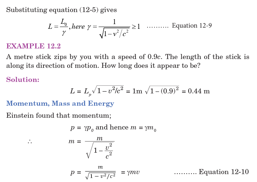
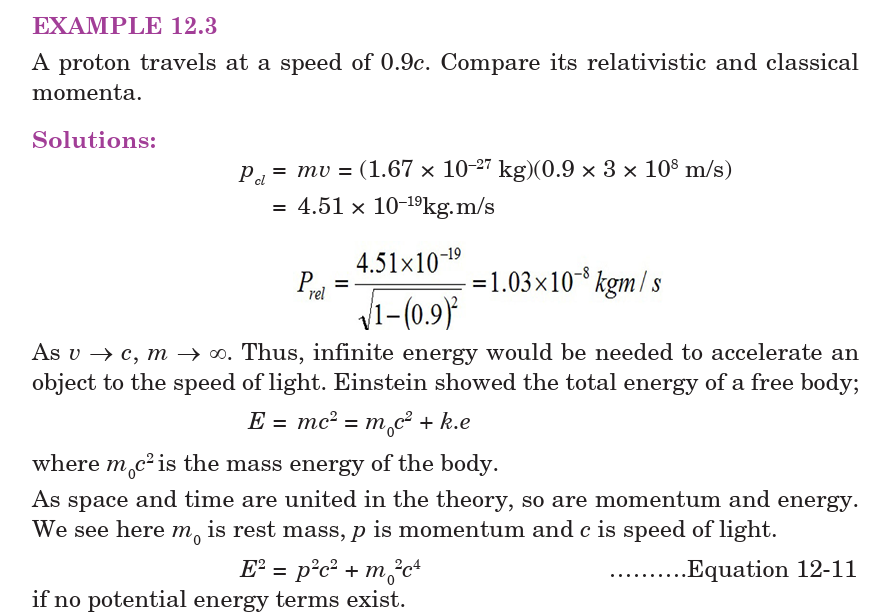

Application Activity 12.1
12.3 CONCEPT OF FRAME OF REFERENCE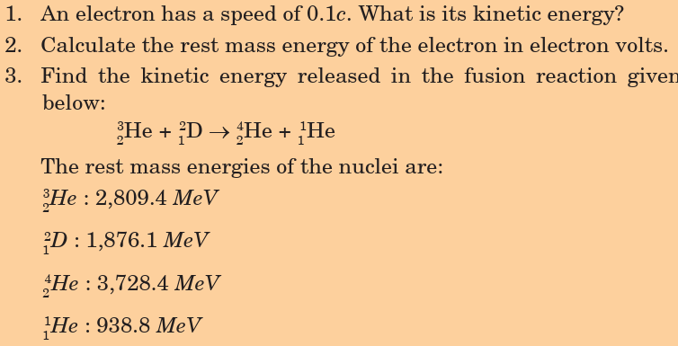
Imagine you threw and caught a ball while you were on a train moving at
a constant velocity past a station. To you, the ball appears to simply travel
vertically up and then down under the influence of gravity. However, to an
observer stood on the station platform, the ball would appear to travel in
a parabola, with a constant horizontal component of velocity equal to thevelocity of the train. This is illustrated in Fig.12-4 below.
The different observations occur because the two observers are in different
frames of reference.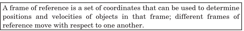
This means that when you are standing on the ground, that is your frame
of reference. Anything that you see, watch or measure will be compared to
the reference point of the ground. If a person is standing in the back of a
moving truck, the truck is now the frame of reference and everything will
be measured compared to it.
Types of Frame of Reference
There are two types of frames of reference.
Inertial Frame of Reference: It is a frame of reference in which a body
remains at rest or moves with constant linear velocity unless acted upon
by forces. Any frame of reference that moves with constant velocity with
respect to an inertial system is itself an inertial system. In other words, itis the frame of reference in which Newton’s first law of motion holds good.
Non-inertial Frame of Reference: This is a frame of reference that is
undergoing acceleration with respect to an inertial frame. An accelerometer
at rest in a non-inertial frame will in general detect a non-zero acceleration.In this frame of reference, Newton’s first law of motion does not hold good.
12.4 GALILEAN EQUATION OF TRANSFORMATION
Galilean transformations, also called Newtonian transformations, are set
of equations in classical physics that relate the space and time coordinates
of two systems moving at a constant velocity with respect to each other.
Galilean transformations formally express the ideas that space and time
are absolute; that length, time, and mass are independent of the relative
motion of the observer; and that the speed of light depends upon the relative
motion of the observer.
Let there be two inertial frames of references S and S′ where S is the
stationary frame of reference and S′ is the moving frame of reference. At
time t = t′ = 0, i.e., in the start, they are at the same position, i.e., observers
O and O′ coincide. After that S′ frame starts moving with a uniform velocity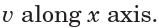
Let an event happen at position A in
the frame S′. The coordinate of the P will be x′ according to O′, the observer
in S′ and it will be x according to O in S. The frame S′ has moved a distance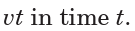
The Galilean transformation relates the coordinates of events as measured
in both frames. Given the absolute nature of time, Newtonian physics, it isthe same for both frames. So, this may look over-elaborate if we write.
Activity 12-1: Frames of Reference
Aim: this activity aims at explaining the frames of reference.
a) How many passengers are moving? How many passengers are notmoving? Explain your answer.
b) How many images there on the frame? Explain your answer. (do not
consider the ground and the sky)
12.5 POSTULATES OF SPECIAL THEORY OF
RELATIVITY
With two deceptively simple postulates and a careful consideration of how
measurements are made, Einstein produced the theory of special relativity.
First postulate: The Principle of Relativity
This states that the laws of physics are the same in all inertial frames of
reference.
This postulate relates to reference frames. It says that there is no preferred
frame and, therefore, no absolute motion.
To understand the meaning of this postulate, consider the following
situation.
You are sitting in a train that is stopped at a railway station. Another train
is facing the opposite direction on the track directly beside you. Ten minutes
before your train is due to leave, you look out through the window at the
other train and see that it is slowly starting to move relative to yours. Your
first reaction would probably be one of surprise: your train was leaving
early! After passing the train from your window, you might notice that the
station was still there, and you realize that it was the other train that was
moving.
Second postulate: The Principle of Invariant Light Speed
The speed of light is a constant, independent of the relative motion of the
source and observer.
The speed of light in vacuum (c = 3 × 10⁸ m/s ) is so high that we do not notice
a delay between the transmission and reception of electromagnetic waves
under normal circumstances. The speed of light in vacuum is actually the
only speed that is absolute and the same for all observers as was stated in
the second postulate.
12.6 CONCEPT OF SIMULTANEITY
The concept of simultaneity says that two events that are simultaneous to
one observer are not necessarily simultaneous to a second observer. Both
observers are correct in their observations -- there is no best or preferred
frame of reference.
If the speed of light is the same in all moving coordinate systems, this means
that events that occur simultaneously in one system may not be observed asbeing simultaneous in another coordinate system.
An example is illustrated in the Fig. 12.7 below.
An observer O′ stands in the middle of a moving boxcar and another observer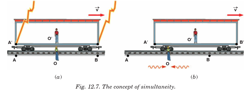
O stands at rest beside the track. When the positions of the observers
coincide, a lightning bolt strikes at each end of the boxcar, leaving mass on
the ground and at each end of the boxcar. The light from the lightning strikes
at A and B reaches to observer O at the same time, so observer O′ concludes
that the lightning strikes occurred simultaneously. But to observer O′ in
the moving boxcar, the lightning strikes do not appear to occur at the same
time. The light traveling from A′ to O′ travels further than the light from B′
to O′. Because of the motion, O′ moves towards the incoming beam from B′
and away from the incoming beam from A′. So to observer O′ the strike at
B′ appeared to occur before the strike at A′.
END OF UNIT ASSESSMENT
1. If you were on a spaceship travelling at 0.50c away from a star, when
would the starlight pass you?
2. Does time dilation mean that time actually passes more slowly in
moving references frames or that it only seems to pass more slowly?
3. If you were travelling away from the Earth at 0.50c, would you notice
a change in your heartbeat? Would your mass, height, or waistline
change? What would observers on the earth using a telescope to see
you say about you?
4. What happens to the relativistic factor
when objects travel
at normal everyday velocities?
5. A spaceship travels at 0.99c for 3 years ship time. How much time
would pass on the earth?
6. A spaceship is travelling at a speed of 0.94c. It has gone from the earth
for a total of 10 years as measured by the people of the earth. Howmuch time will pass on the spaceship during its travel?
7. A spaceship has gone from the earth for a total time of 5 years ship
time. The people on the earth have measured the time for the ship to
be away to 25 years. How fast was the ship travelling?
8. A 520 m long (measured when the spaceship is stationary) spaceship
passes by the earth. What length would the people on the earth say the
spaceship was as it passed the earth at 0.87c?
9. A 25 m long beam is shot past a stationary space station at 0.99c. What
length does the people on board the space station measure the beam to
be?
10. A 100 m long steel beam is moving past the earth. Observers on the
earth actually measure the steel beam to be only 50 m long. How fastwas the beam travelling?
UNIT SUMMARY
Definition of relativity
Anything except light moves with respect to time and space depends on the
position and movement of someone who is watching.
Concept of space, time and mass
• Time Dilation
Time dilation is the phenomenon where two objects moving relative
to each other (or even just a different intensity of gravitational field
from each other) experience different rates of time flow. The totaltime is given by
Postulates of special theory of relativity
• First postulate
This states that the laws of physics are the same in all inertial frames
of reference.
This postulate relates to reference frames. It says that there is no
preferred frame and, therefore, no absolute motion.
• Second postulate
This states that speed of light, c is a constant, independent of therelative motion of the source and observer.
BIBLIOGRAPHY
1. Abott, A. (1989). Physics. Chicago: Heinman Educational Publisher.
2. David, V. F., Griffith, T., John, G. L., Jay, M., Beth, M., Steve, M., &
Camille, W. (2006).
Science Explorer. Mexico: Pearson Prentice hall.
3. Elizabeth, C., Donald, C., Linda, C., Lisowski, M., & Jan, J. (2006).
Science Explorer. Mexico: Pearson Prentice Hall.
4. Nelkon, M., & Parker, H. (1995). Advanced Level Physics. London:
Heinemann.
5. Richard, O. (2009). Physics for Rwanda Secondary School. Kigali:
Fountain.
6. Tom, D. (2000). Advanced Physics. London: Hodder Education.
7. Wysession, M., Frank, D., & Yancopoulos, S. (2004). Physical Science.
Boston, Massachusetts, Upper Saddle River, New Jersey: Pearson
Prentice Hall.
8. Valerio Faraoni,(2003): Exercises on Environmental Physical, Springer,
ISBN-10: 0-387-33912-4 ISBN-13: 978-0387-33912-2
9. Peter Hughes, N.J. Mason,(2001): Introduction to Environmental
Physics: Planet Earth, Life and Climate,
10. Gerard P.A. Bot, (2010): Agricultural Physics. Publisher: Springer,
ISBN: 978-3-540-74697-3, ISBN: 978-3-540-74698-0
11. Franklin Hiram King, (1904): A Text Book of the Physics of Agriculture,
Publisher: Madison, Wis., ISBN: 1176279092 / ISBN-13: 9781176279094
12. Roger A. Freedman and William J. Kaufmann III, (2008): Stars and
galaxies. Universe, Third Edition, W.H. Freeman and Company, New
York. ISBN-13:978-0-7167-9561-2
13. Neil F. Comins, (2009): Discovering the Universe: From the stars to
the Planets, W.H. Freeman and Company, New York. ISBN-13:978-1
4292-3042-1
14. STACY E. PALEN, (2002): Theory and Problems of Astronomy.
Schaumâ ™s Outline Series, McGraw-HILL.
15. STAN GIBILISCO, (2003): Astronomy demystified. McGraw-HILL
16. Marc L. KUTNER,(2003): Astronomy: A Physical Perspective,
Cambridge University Press, ISNB-13:978-0-511-07857-6
17. Stan Gibilisco (2010): Electronics Demystified, Second Edition. ISBN
13: 978-0071768078 ISBN-10: 0071768076
18. Advanced Physics, Tom Duncan, John Murray (2000).
19. Fundamentals of Physics, David Halliday, Robert Resnick and Jearl
Walker, 7th Edition John Wily (2004).
20. Hastings, R. J., 1987, “Creation Physics” and the speed of light;
Unpublished manuscript.
21. Morse, P., 1974, Thermal Physics: New York, Benjamin.
22. Tryon, E. P., 1989, Cosmic Inflation, in Meyers, R. A., ed., Encyclopedia
of Astronomy and Physics: San Diego, California, Academic Press.
23. Weinberg, S., 1977, the First Three Minutes: A Modern View of theOrigin of the Universe: New York, Basic Books.