General
- Y1: Integrated Science ECLPE SB File Uploaded 17/08/22, 09:41
- Y1: Integrated Science ECLPE TG File Uploaded 17/08/22, 09:44
UNIT 8:KIRCHHOFF’S LAWS IN ELECTRIC CIRCUITS
Key unit competence
Analyze complex electric circuits using Kirchhoff’s laws.
Introductory Activity 8
Look carefully and try to interpret the following illustrations and answer thequestions below:
a) What type of electrical devices available in the illustration above?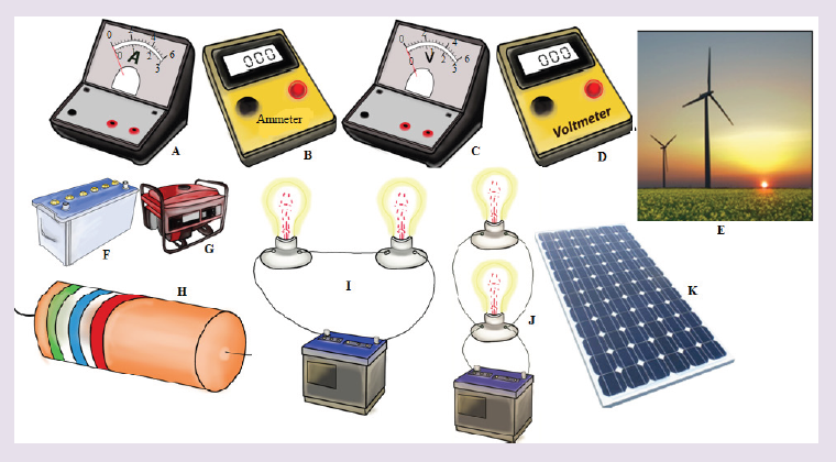
b) Suggest the names of the available devices in the illustration above?
c) Is there any complete circuit in the illustration above? What kind of
electrical circuits identified in the illustration above?
d) Have you ever used or connected these electrical components
somewhere? If yes, what were the difficulties in handling these
electrical components in circuit construction?
e) What can be considered to select the best electrical device(s) to be
used in electrical circuit construction?
f) What can be put in recognition when manipulating these electrical
components to minimize risks in the process of circuit construction?
8.1 Simple electric circuit and its construction
Activity 8.1
Making a simple electric circuit with a battery, bulb(s) , and wires
Task1: Making a series circuitProvided materials: 1 battery,aswitch,3 pieces of copper wire and bulb(s).
Technical procedures: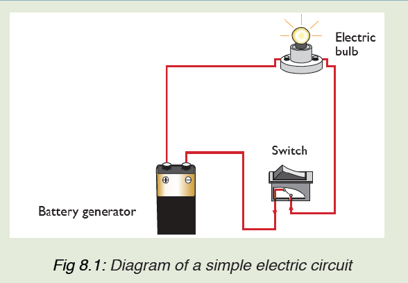
i. Arrange the battery as shown in figure above.
ii. Connect the bulb in series with other components and switch on.
iii. Switch off and explain what happens to the bulb?
iv. Explain what makes the bulb light?
Task 2 :Making a parallel circuit
Provided materials: 1 battery,3 bulbs,Assembled battery holder, 3 bulb
holders and 4 pieces of copper wire.
Technical procedures:
i. Construct a complete circuit with one battery and one bulb.
ii. Using other two wires, add a second bulb as shown in the figurebelow.
iii. What do you notice happened to the first bulb when the second bulb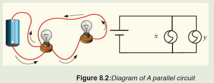
was added?
iv. Look carefully at how a parallel circuit is set up. Write a prediction
of what you think will happen if you unscrew one of the bulbs in the
parallel circuit. By comparing your prediction and the observation,
explain your observation?
v. Unscrew bulb “X”. Describe what happens to bulb “Y”.
vi. Tighten bulb “X” and unscrew bulb “Y”. Describe what happens to
bulb “X”.
vii. Based on the performed experiments for series and parallel circuits,
a) What advantages and disadvantages can you recognize in two
cases above?
b) Identify the characteristics of a series connection and a parallel
connection?
Task 3: Making a simple electric circuit with a bulb, a battery and wires
Provided materials: 2 pieces of copper wire,1 bulb, and 1 battery
Procedure
1. Examine diagrams A-J below. Predict whether the circuit will be
complete, and record your prediction on the chart below.
2. Your tutor, with a helper, demonstrate the arrangements to testyour predictions. Record your results on the chart below
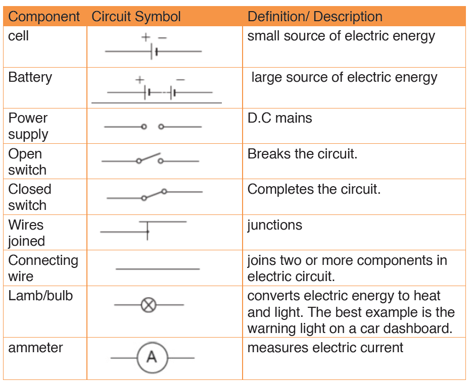
8.1.1 Electric circuit components and their symbols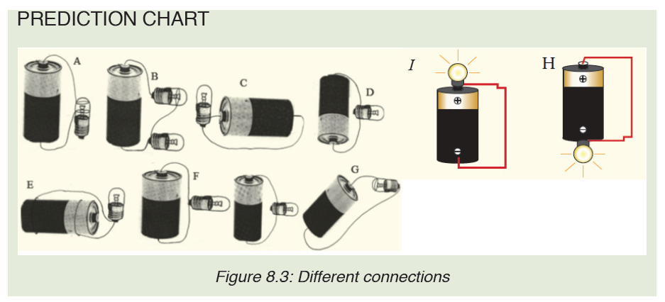
In electric circuit diagrams, we represent the actual components with
symbols. Table below shows some of the components, their symbols anddefinition that are used in electric circuit diagrams.
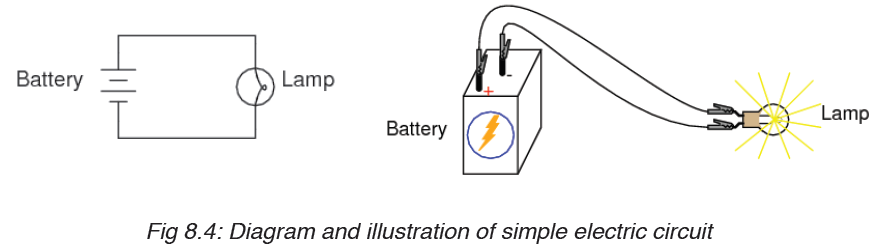
8.1.2 Sample arrangement of electric components in a simple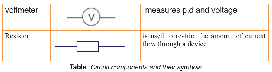
electric circuit.
Remember the cell provides electrical energy needed to light the bulb.
The bulb converts electrical energy into light and heat energy.
A cell is a kind of a ‘pump’ which provides electrical energy needed to drive
charges along a complete path formed by the wire through the bulb switch
and back again to the cell.
When the switch is open, the bulb does not light. This is called an open
circuit. When the bulb lights the circuit is called closed circuit.
In a series circuit, the current is the same at all points; it is not used up. In a
parallel circuit the total current equals the sum of the currents in the separate
branches.• Schematic diagram and its corresponding illustrations:
• ILLUSTRATION OF BREAK IN ELECTRIC CIRCUITS
Application activity 8.1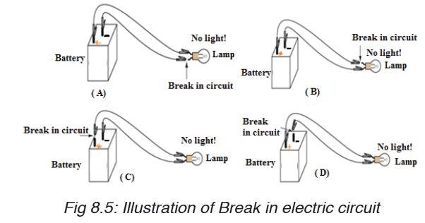
1. Define the term electric circuit.
2. Draw a diagram for a simple circuit using preferable electric
components.
3. What is an open circuit?
4. Draw a labeled diagram of a simple cell.4. The following are some symbols of electric components.

a) Name the electric components represented by these symbol.
b) Using these symbols, draw a simple circuit diagram.
8.2. Voltage or terminal potential and electromotive force in
electric circuit.
Activity 8.2
Provided different dry cells ammeter and voltmeters. Read the value ofvoltage labeled on each dry cell and complete this table.
Any other comment: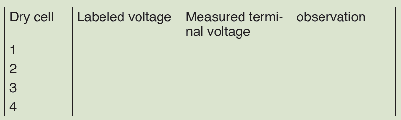
………………………………………………………………………….
….………………………………………………………………………………………………
8.2.1 Potential difference (p.d)
Potential difference is defined as the work done in moving one coulomb
of charge from one point to the other in an electrical circuit. The SI unit of
potential difference is the volt (V).
In the electric circuit, the electrons move towards the positive terminal of the
battery. The battery lifts the electrons up through an electrical height. This
electrical height is called a potential.
The positive and the negative terminals have a difference in potential. Thepotential difference is also known as the voltage.
• The volt
Volt is defined as energy consumption of one joule per electric charge of one
coulomb.
• MEASUREMENT OF VOLTAGE
Figure (A) shows analog voltmeter and (B) shows digital voltmeter the
symbol for a voltmeter. A voltmeter is used to measure voltage across adevice in an electric circuit.
The positive terminal of voltmeter is connected to the wire from the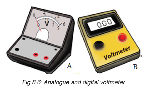
positive terminal of the cells and the negative terminal to the wire leading
to negative terminal. A voltmeter is always parallel to the device whosevoltage is to be measured.
Voltmeters have uniform scales calibrated in volts or millivolts. The most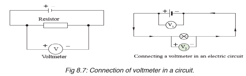
used scales have a range of 0 – 5 V and 0 – 1.5 V. Figure below shows ascale of a voltmeter.
8.2.2 Electromotive force.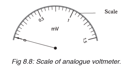
Electromotive force is voltage, or the difference in the electric tension or the
difference in charge between two points that causes an electric current.
The potential difference between two points of a conductor creates an
electromotive force which pushes free electrons in a conducting material
to move towards the positive terminal, creating current.
Electromotive force, or, as it is often written, e.m.f., may be described as that
source of energy which enables electrons to move around an electric circuit.
It is now necessary to define this quantity.
For anything to move from rest, there must be some energy change. To
enable electrons to move round an electrical circuit, they must receive
energy from the source of e.m.f. which is usually a battery or a generator.
Note:
– The terminal potential difference (or voltage) of a battery or generator
when it delivers a current, I is related to its electromotive force, and its
internal resistance r as follows:
1. When delivering current ( on discharge):Terminal voltage = Electromotive force –Voltage drop in internal resistance
V =ε − Ir
2. When receiving current ( on charge):
Terminal voltage = emf + (Voltage drop in internal resistance)
3. When no current exists:
Terminal voltage = Emf of battery or generator.
All voltage sources have two fundamental parts: a source of electrical
energy that has a characteristic electromotive force (emf), and an internal
resistance . The emf is the potential difference of a source when no current
is flowing.
The numerical value of the emf depends on the source of potential difference.
The internal resistance of a voltage source affects the output voltage when
a current flows.
The voltage output of a device is called its terminal voltage and is given by,
where I is the electric current and is positive when flowing away from the
positive terminal of the voltage source.When multiple voltage sources are inseries, their internal resistances add and their emfs add algebraically.
Consider the circuit shown in Figure 8.9.A, consisting of a battery connected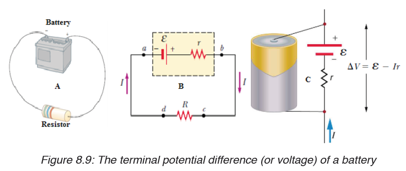
to a resistor. We generally assume that the connecting wires have no
resistance. The positive terminal of the battery is at a higher potential than
the negative terminal. Because a real battery is made of matter, there is
resistance to the flow of charge within the battery. This resistance is called
internal resistance r.
For an idealized battery with zero internal resistance, the potential difference
across the battery (called its terminal voltage) equals its emf. However, for
a real battery, the terminal voltage is not equal to the emf for a battery in a
circuit in which there is a current.
Now imagine moving through the battery from a to b and measuring the
electric potential at various locations. As we pass from the negative terminal
to the positive terminal, the potential increases by an amount . However, as
we move through the resistance r,
the potential decreases by an amount Ir, where I is the current in the circuit.
Thus, the terminal voltage of the battery,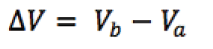
Example 1 :
A battery has an emf of 12.0 V and an internal resistance of 0.05 Ω. Its
terminals are connected to a load resistance of 3.00Ω. Find the current in
the circuit and the terminal voltage of the battery.
Solution:It is possible to calculate current from the equation given by:
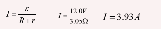
And from equation, we find the terminal voltage; ΔV =ε − Ir ,
ΔV =12.0V − (3.93A)(0.05Ω) =11.8V
To check this result, we can calculate the voltage across the load
resistance R:
ΔV = IR = (3.93 A)(3.0Ω) =11.8V
Example 2
The current in the figure below is 0.125 A in the direction shown. For each
of the following pairs of points, what is their potential difference, and which
point is at the high potential?a) A, B; b) B, C; c) C,D; d) D,E; e) C,E ; f) E,C.
Solution: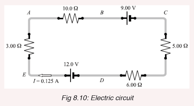
Recall the following facts:
1. The current is the same (0.125 A) at all points in this circuit because
the charge has no other place to flow.
2. Current always flows from high to low potential through a resistor.
3. The positive terminal of a pure emf (the long side of its symbol)
is always the high-potential terminal. Therefore, taking potential
drops as negative, we have the following: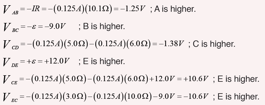
Notice that the answers to e) and f) agree with each other.
Application activity 8.2
1. Define the term potential difference and state its SI units.
2. Name the instrument used to measure voltage.
3. Define a volt.
4. In a circuit, 5 joules are used to drive 2 coulombs of charge across a
bulb in a simple circuit. Find the potential difference across the bulb?
5. Name the instrument used to measure potential difference.
6. Two cells, A and B connected in parallel are in series with a bulb asshown in Figure below.
Copy the diagram and show where the: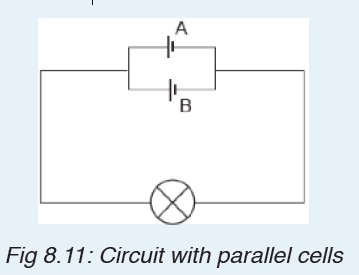
a) ammeter should be connected in order to measure the current
through cell A.
b) voltmeter should be connected to measure the potential difference
across both the bulb and cell B.
7. A dry cell has an emf of 1.52 V. Its terminal potential drops to
zero when a current of 25 A passes through it. What is its internal
resistance?
8.3. Electric receptors and Sources of electric current
Activity 8.3Look and interpret the illustrations and try to answer questions that follow:
a) What is a source of electric current based on the images above?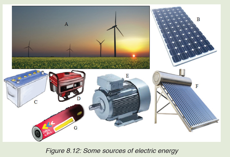
b) What is another name of electric source of energy?
c) Suggest some of electric sources you have found.
d) On the picture above are some sources of electric energy. Name
them and tell what the common role they have is.
e) Tell what energy is changed in electric energy for each device.
8.3.1 Sources of electric current
There are several different devices that can supply the voltage necessary to
generate an electric current. The two most common sources are generators
and electrolytic cells.
Generators use mechanical energy, such as water pouring through a dam or
the motion of a turbine driven by steam, to produce electricity. The electric
outlets on the walls of homes and other buildings, from which electricity to
operate lights and appliances is drawn, are connected to giant generators
located in electric power stations. Each outlet contains two terminals. The
voltage between the terminals drives an electric current through the appliance
that is plugged into the outlet.
Generator electrolytic cells use chemical energy to produce electricity.
Chemical reactions within an electrolytic cell produce a potential difference
between the cell’s terminals. An electric battery consists of a cell or group of
cells connected together.
There are many sources of electric current other than mechanical generators
and electrolytic cells. Fuel cells or engines, for example, produce electricity
through chemical reactions. Unlike electrolytic cells, however, fuel cells do
not store chemicals and therefore must be constantly refilled.
Certain sources of electric current operate on the principle that some metals
hold onto their electrons more strongly than other metals do. Platinum, for
example, holds its electrons less strongly than aluminum does. If a strip of
platinum and a strip of aluminum are pressed together under the proper
conditions, some electrons will flow from the platinum to the aluminum. As
the aluminum gains electrons and becomes negative, the platinum loses
electrons and becomes positive.
The strength with which a metal holds its electrons varies with temperature.
If two strips of different metals are joined and the joint heated, electrons will
pass from one strip to the other. Electricity produced directly by heating is
called thermoelectricity.
Some substances emit electrons when they are struck by light. Electricity
produced in this way is called photo-electricity. When pressure is applied
to certain crystals, a potential difference develops across them. Electricity
thus produced is called piezoelectricity. Some microphones work on this
principle.
Notice: An electric generator is a device which is used to produce electric
energy, which can be stored in batteries or can be directly supplied to the
homes, shops, offices, etc. Electric generators work on the principle of
electromagnetic induction. A conductor coil (a copper coil tightly wound
onto a metal core) is rotated rapidly between the poles of a horseshoe type
magnet. A conductor coil (a copper coil tightly wound onto a metal core) is
rotated rapidly between the poles of a horseshoe type magnet. The conductor
coil along with its core is known as an armature. The armature is connected
to a shaft of a mechanical energy source such as a motor and rotated. The
mechanical energy required can be provided by engines operating on fuels
such as diesel, petrol, natural gas, etc. or via renewable energy sources
such as a wind turbine, water turbine, solar-powered turbine. When the coil
rotates, it cuts the magnetic field which lies between the two poles of the
magnet. The magnetic field will interfere with the electrons in the conductor
to induce a flow of electric current inside it.
Physical sources such as batteries and generators may be regarded as
approximations to ideal voltage sources. Figure below shows the symbolsfor independent voltage sources.
Cells connected in Series or parallel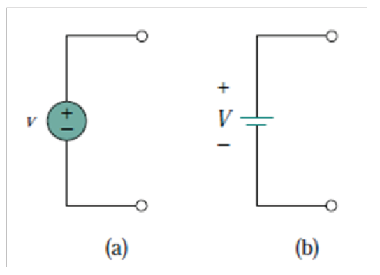
The electromotive force (e.m.f.), ε , of a cell is the p.d. between its terminals
when it is not connected to a load (i.e. the cell is on ‘no load’).
The e.m.f. of a cell is measured by using a high resistance voltmeter
connected in parallel with the cell. The voltmeter must have a high resistance
otherwise it will pass current and the cell will not be on no-load.
The voltage available at the terminals of a cell falls when a load is connected.
This is caused by the internal resistance of the cell which is the opposition
of the material of the cell to the flow of current.
The internal resistance acts in series with other resistances in the circuit. the
figure below shows a cell of e.m.f. ε volts and internal resistance, r , and XYrepresents the terminals of the cell.
When a load (shown as resistance R) is not connected, no current flows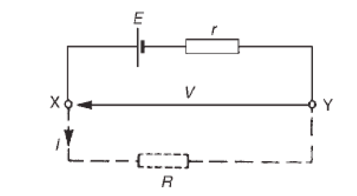
and the terminal p.d., V =ε . When R is connected a current I flows which
causes a voltage drop in the cell, given by r V = Ir . The p.d. available at the
cell terminals is less than the e.m.f. of the cell and is given by:
V =ε − rI
When different values of potential difference V, across a cell or power supply
are measured for different values of current I, a graph may be plotted as
shown in figure below. Since the e.m.f. ε of the cell or power supply is the
p.d. across its terminals on no load (i.e. when I = 0 ), then ε is as shown bythe broken line.
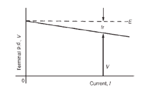
Since V =ε − rI then the internal resistance may be calculated from
When a current is flowing in the direction shown in Figure above the cell is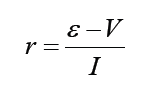
said to be discharging (ε >V )
When a current flows in the opposite direction to that shown in Figure
above the cell is said to be charging ε <V
A battery is a combination of more than one cell. The cells in a battery
may be connected in series or in parallel.
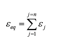
(i) For cells connected in series:Total e.m.f. εeq sum of cell’s e.m.f.
Total internal resistance req = sum of cell’s internal resistances
Example 1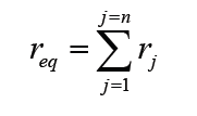
1. Three cells each of emf of 1.5 V and internal resistance 0.6 Ω are connected
in series to form a battery. What current passes or flows when
the battery is connected across a 5 Ωresistance and what is the potential
difference across the terminal of the battery?Answer
The pd across the terminal of battery: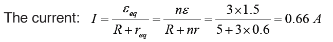
V = nε − nri = 3×1.5 − 3×0.6×0.66 = 3.31V
(ii) For cells connected in parallel:
If each cell has the same e.m.f. and internal resistance:Total e.m.f. ε eq = e.m.f. of one cell i.e.ε eq =ε
Total internal resistance of n cells
Example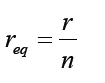
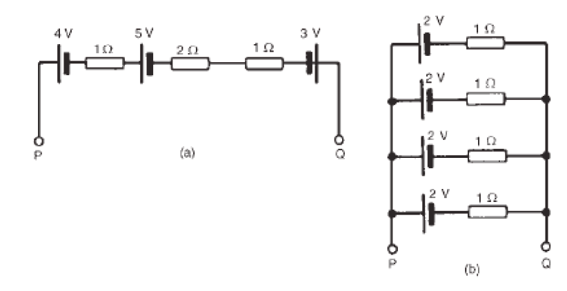
1. For the circuits shown in Fig. the resistors represent the internal resistance
of the batteries. Find, in each case:
i. the total e.m.f. across PQii. the total equivalent internal resistances of the batteries
8.3.2 Electrical receptors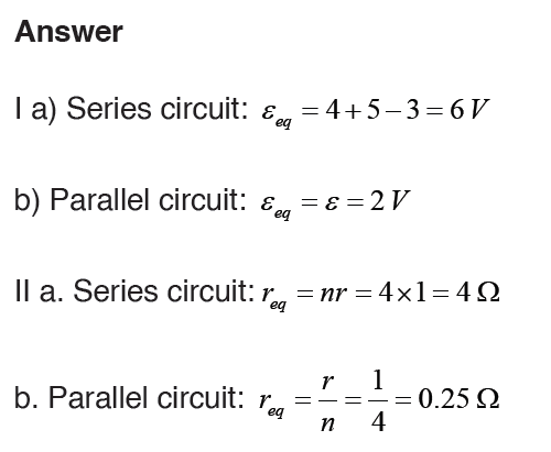
A receptor is any electrical device that can transform electrical energy into
any other form of energy. Example: the lamp, the motor, clippers, iron,
electric cookers.
Passive receptors (thermal receptors) transform electrical energy into
heat energy only by the joule effect. Examples: bulbs, electric irons, electric
heaters.
Active receptors are capable of transforming electric energy not only into
heat energy but also into other forms of energy. Examples: electric motors,
batteries (secondary cells).
An active receptor is characterized by its counter-electromotive force and its
internal resistance.
The counter-electromotive force also known as back electromotive force
(cemf). It is its capacity of transforming a part of energy (electricity) in other
form of energy (except heat). It is also the voltage, or electromotive force, that
pushes against the current which induces it. CEMF is caused by a changing
electromagnetic field. Back electromotive force is a voltage that occurs in
electric motors where there is relative motion between the armature of the
motor and the external magnetic field.
The internal resistance of an active receptor is the measure of its capacity
to absorb heat energy by the joule effect when a current is flowing through it.Back electromotive force of an active receptor is the ratio:
where P is the Power it transforms into energy other than heat and I electric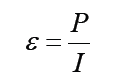
current.
Receptors are often associated in parallel because in series there will be
a big loss of energy. And to associate receptors in series, we will need a
generator which also will be in series.
In Series
If we have n identical receptors characterized by cemf εk and rk for each
receptor, k =1, 2,3,...,n k =1, 2, 3, ......n all in series with a cell (E) and external
resistance R e, the total internal resistances of receptors will be rt= nr k andthe total cemf εk = nεk Then the intensity is
In Parallel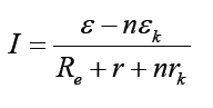
As we know that for parallel the potential difference is the same for each
blanch, here also if we have n receptors in parallel, the c.e.m.f of one is thesame for others. The total internal resistance is
The power consumed by the receptor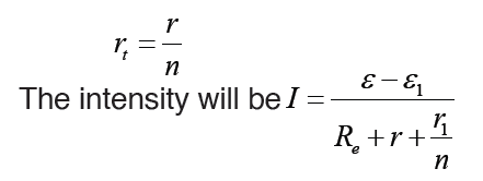
The electric energy produced by the cell to the receptor transforms partially
into heat (Joule’s effect) into chemical energy (voltameter) or into mechanical
energy (motor). The energy produced per second by cell is:P =ε I
Application activity 8.3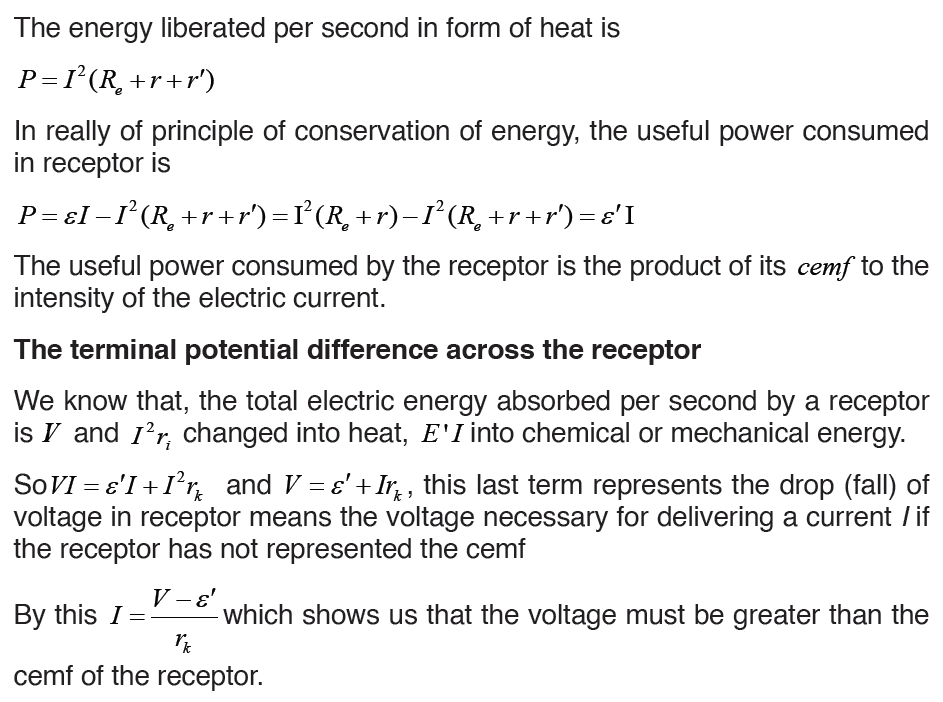
1. Explain the difference between load resistance in a circuit and internal
resistance in a battery.
2. Is the direction of current through a battery always from the negative
terminal to the positive terminal? Explain.
3. A real battery with an emf of provides 50 W to an external resistance
of 4.
a) Find the internal resistance of the battery.
b) For what value of external resistor the supplied power is 100 W?
4. What is the internal resistance of the battery in the following circuit?
5. A battery has an emf of 15.0 V. The terminal voltage of the battery is
11.6 V when it is delivering 20.0 W of power to an external load resistor R.
a) What is the value of R?b) What is the internal resistance of the battery?
8.4. Connection of resistors either in series or parallel or
mix-up
Activity 8.4
Task1: Arrangement of resistors in series circuits.
Provided materials: Battery cells, three torch light bulbs and 4
conducting wires
Technical procedures:
– Arrange the battery cells as shown in figure below and connect all the
two bulbs in series and switch on.
– Remove one bulb and notice what happens based on your
observations.
– Arrange the circuit to have two bulbs, and then to have one bulb andnotice the observation.
Use your observations to answer the following questions: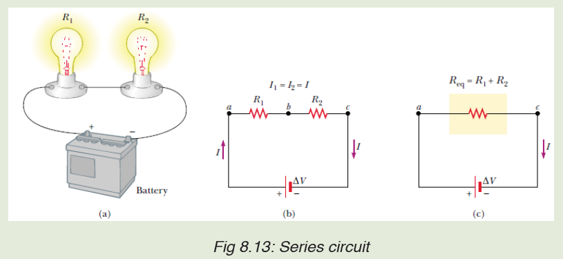
a) What happens in the circuit with three bulbs when one bulb is removed?
b) What happens when the circuit has two bulbs?
c) What happens when the circuit has one bulb only?
Task 2: Arrangement of resistors in series circuits
Technical Procedures:
– Arrange the battery cells as shown in figure below and connect all the three
bulbs in parallel and switch on.
– Remove one bulb and notice your observations. Remove the second bulband notice your observations.
Use your observation to answer to questions below: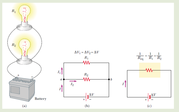
a) Explain what happens in the circuit with two bulbs when one bulb
is removed?
b) What happens when the circuit has two bulbs?
c) What happens when the circuit has one bulb only
Circuits consisting of just one battery and one load resistance are very
simple to analyze, but they are not often found in practical applications.
Usually, we find circuits where more than two components are connected
together. There are two basic ways in which to connect more than two circuit
components: series and parallel.
8.4.1 Resistors in series
The defining characteristic of a series circuit is that there is only one path for
electrons to flow. Consider three resistors R1, R2 and R3 connected in series
across a battery of potential difference V. Across the resistors the potential
difference drops are V1, V2 and V3 but the current flow I is constant due to thesame amount of charges flowing across each resistor.
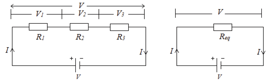
For any n resistors connected in series combination, the effective resistance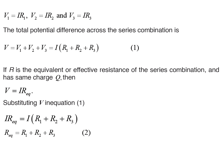
is
Req = R1 + R2 + R3 + R......n
8.4.2 Resistors in parallel
The defining characteristic of a parallel circuit is that all components are
connected between the same set of electrically common points and the
resistors form more than one continuous path for electrons to flow.
Assume three resistors of resistance R1, R2 and R3connected in parallel
across a battery of potential difference V. The potential difference across
each resistor is the same and is equal to the potential difference V across
the battery, but the current flow splits into three parts I1, I2 and I3 due to theseparation of charges
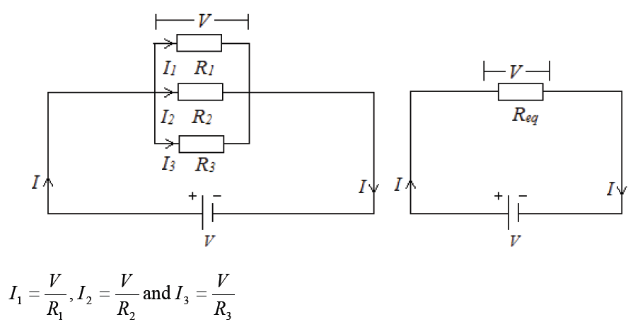
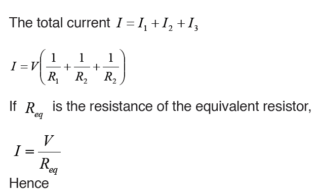
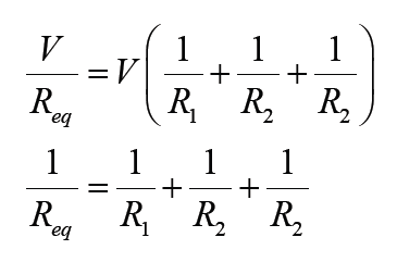
For n resistors connected in parallel combination, the effective resistance is
Household circuits are always wires so that the lights and appliances are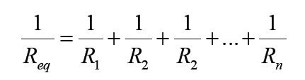
connected in parallel. This way each device operated independently of
the others, so if one is turned off the others remain on. This also had the
advantage that the voltage supplied to each element is the same.Example1: Find the equivalent resistance in the circuit below:
Example 2: A parallel circuit is shown in the figure below. In this case the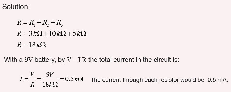
current supplied by the battery splits up, and the amount going through
each resistor depends on the resistance.
From the figure below, if the values of the three resistors are
R1 = 8Ω, R2 = 8Ω, and R3 = 4Ω .Determine the total resistance of the circuit.
Solution: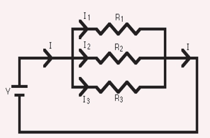
The total resistance R is found by
This gives that R = 2Ω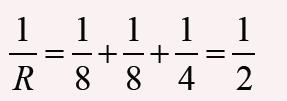
With a 10 V battery, by V = I R the total current in the circuit is:
Note that the currents add together to 5A, the total current.
Example 3: Interpret the circuit below and determine the total resistanceof the circuit.
Solution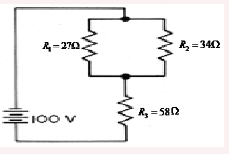
Here we can use the shorter product over sum equation as we only havetwo parallel resistors.
1. Use the concept of equivalent resistance to determine the unknown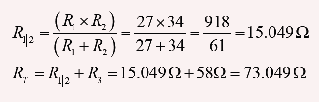
resistance of the identified resistor that would make the circuit’s equivalent.
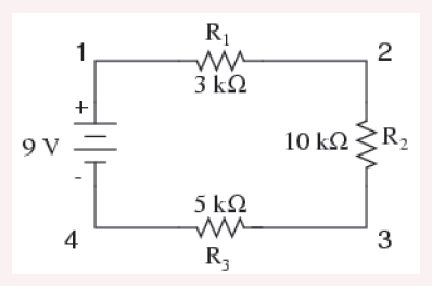
2. A parallel pair of resistance of value of 3Ω and 6Ωare together connected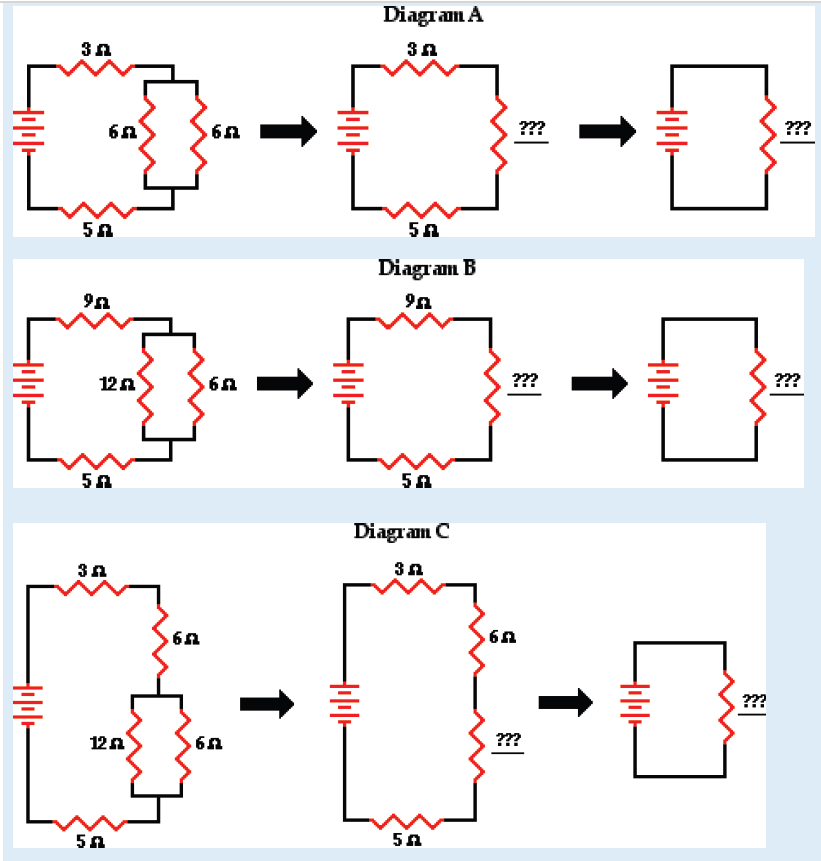
in series with another resistor of value 4 Ω and a battery of e.m.f. 18 V asshown on the fig. (a) below. Calculate the current through each resistor.
3. (a) Find the equivalent resistance between points a and b in Figure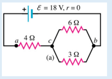
below. (b) A potential difference of 34.0 V is applied between points aand b. Calculate the current in each resistor.
4. Use your understanding of equivalent resistance to complete the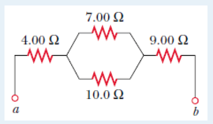
following statements:
i. Two 3 Ω resistors placed in series would provide a resistance which
is equivalent to one ___ Ω resistor.
ii. Three 3 Ω resistors placed in series would provide a resistance
which is equivalent to one ___ Ω resistor.
iii. Three 5 Ω resistors placed in series would provide a resistance
which is equivalent to one ___ Ω resistor.
iv. Three resistors with resistance values of 2 Ω, 4 Ω and 6 Ω are
placed in series. These would provide a resistance which is equivalent
to one ___ Ω resistor.
v. Three resistors with resistance values of 5 Ω, 6 Ω and 7 Ω are
placed in series. These would provide a resistance which is equivalent
to one _____ Ω resistor.
vi. Three resistors with resistance values of ,3 Ω and are
placed in series. These would provide a resistance which is equivalent
to one _____ Ω resistor.
5. As the number of resistors in a series circuit increases, the overall
resistance __________ (increases, decreases, remains the same) and
the current in the circuit __________ (increases, decreases, remains the
same).
6.Imagine that we add a third resistor in series with the first two. Does the
current in the battery (a) increase, (b) decrease, or (c) remain the same?
Does the terminal voltage of the battery (d) increase, (e) decrease, or (f)remain the same?
7. Imagine that we add a third resistor in parallel with the first two. Does the
current in the battery (a) increase, (b) decrease, or (c) remain the same?
Does the terminal voltage of the battery (d) increase, (e) decrease, or (f)
remain the same?
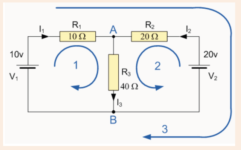
8.5. Kirchhoff’s laws and its applications in solving
problems in complex electric circuits
Activity 8.5
A single-loop circuit contains two resistors and two batteries, as shown in
figure 5.34 (neglect the internal resistances of the batteries). (a) Find the
current in the circuit. (b) What power is delivered to each resistor? Whatpower is delivered by the 12V battery?
8.5.1 Kirchhoff’s laws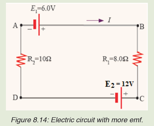
Simple circuits can be analyzed using the expression V = IR and the rules for
series and parallel combinations of resistors. Very often, however, it is not
possible to reduce a circuit to a single loop.
The procedure for analyzing more complex circuits is greatly simplified if
we use two principles called Kirchhoff’s rules developed by the German
Physicist Gustav Robert Kirchhoff (1824-1887).
First, here are two terms that we will use often. A junction in a circuit is a
point where three or more conductors meet. Junctions are also called nodes
of branch points. A loop is any closed conducting path.
In figure below, the points a and b are junctions, but points c and d are not.The curved lines show some possible loops in this circuits.
Kirchhoff’s junction rule: “the algebraic sum of the currents into any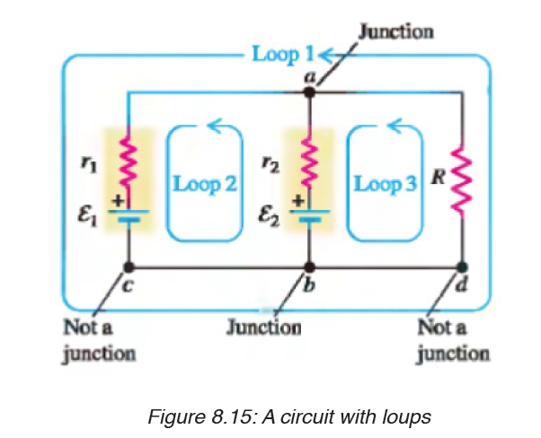
junction is zero.” That is,
i.e The sum of the currents entering the junction must equal the sum of the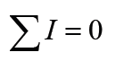
currents leaving the junction.
Kirchhoff’s loop rule: “the algebraic sum of the potential differences in
any loop, including those associated with emfs and those of resistiveelements must equal zero”. That is,
Kirchhoff’s first rule is a statement of conservation of electric charge. All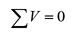
charges that enter a given point in a circuit must leave that point because
charge cannot build up at a point.
Kirchhoff’s second rule follows from the law of conservation of energy.
The sum of the increases in energy as the charge passes through some
circuit elements must equal the sum of the decreases in energy as it passes
through other elements. The potential energy decreases whenever the
charge moves through a potential drop –IR across a resistor or whenever it
When applying Kirchhoff’s second rule in practice, we imagine traveling
around the loop and consider changes in electric potential, rather than the
changes in potential energy.
Problem solving strategy:
1. Junction rule. Assign symbols and directions to the currents in the
various junctions. If you guess the wrong direction for a current it
does not matter. The end result will be a negative answer for that
current and the magnitude will be correct.
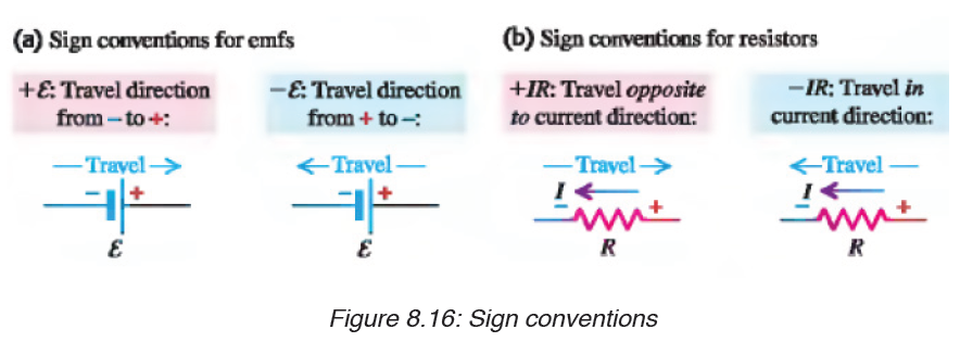
2. Loop rule. You must choose a direction for moving around the loop.
As you move around the loop the voltage drops and increases should
be recorded according to the rules (a-d) below.
a) If a resistor is traversed in the direction of the current, the change in
potential across the resistor is –IR.
b) If a resistor is traversed in the direction opposite the current, the
change in potential across the resistor is +IR.
c) If a source of emf is traversed in the direction of the emf (from – to +)
the change in potential is
d) If a source of emf is traversed opposite the direction of the emf (from
+ to –) the change in potential is
moves in the reverse direction through a source of emf. The potential energy
increases whenever the charge passes through abattery from the negativeterminal to the positive terminal.
Example
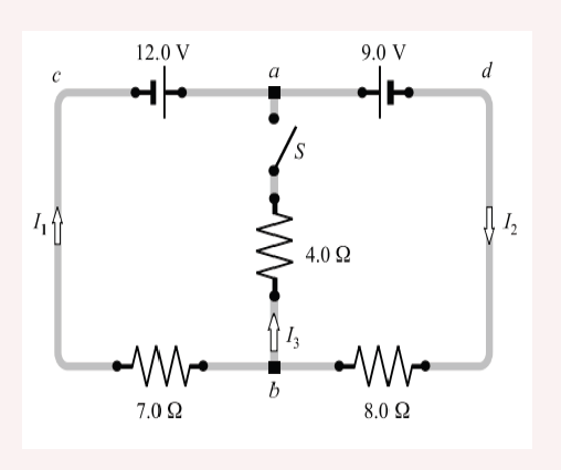
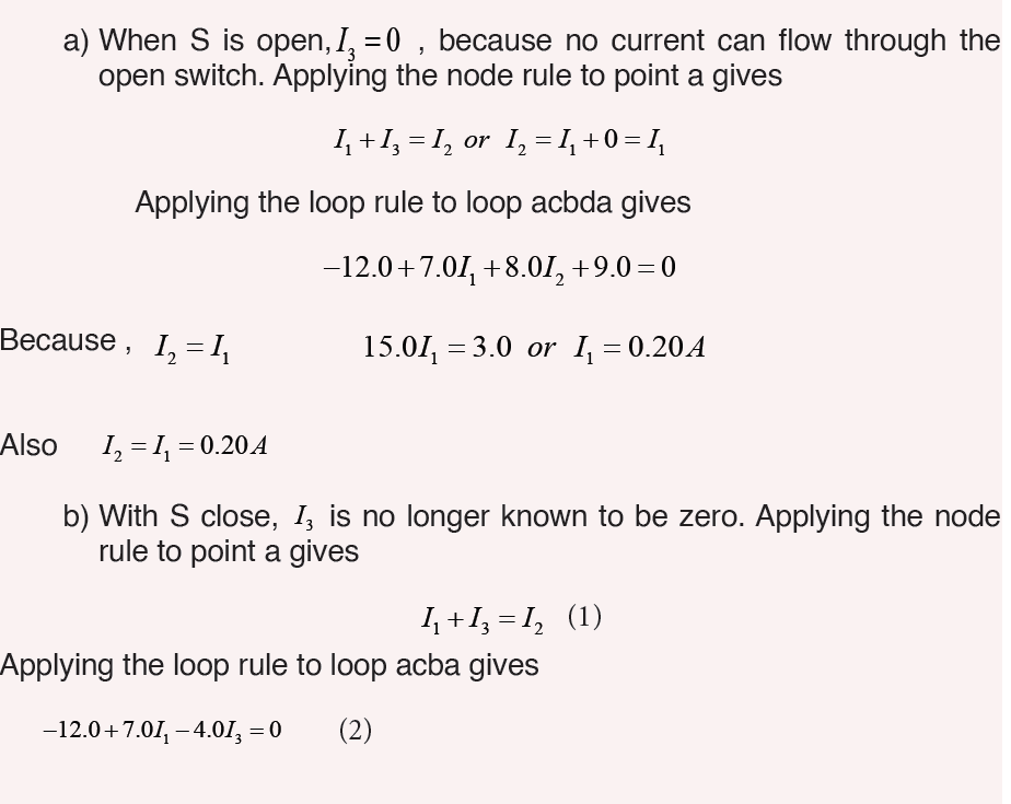
1. In figure below, find I1, I2, and I3 if S is
a) Open
b) Closed
8.5.2 Application of Kirchhoff’s laws in solving problems in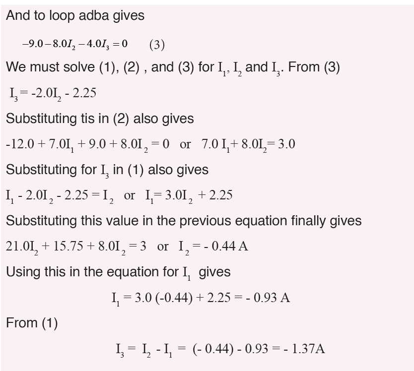
complex electric circuitsExample 1: Find the currents in the circuit given below:
Solution:
This circuit cannot be reduced further because it contains no resistors in
simple series or parallel combinations. We therefore revert to Kirchhoff’s
rules. If the currents had not been labeled and shown by arrows, we would
do that first. No special care needed to be taken in assigning the current
directions, since those chosen incorrectly will simply give negative numerical
values.
We apply the node rule to node b in the figure above.Current into b = Current out of b.
The minus sign tells us that I3 is opposite in direction to that shown in the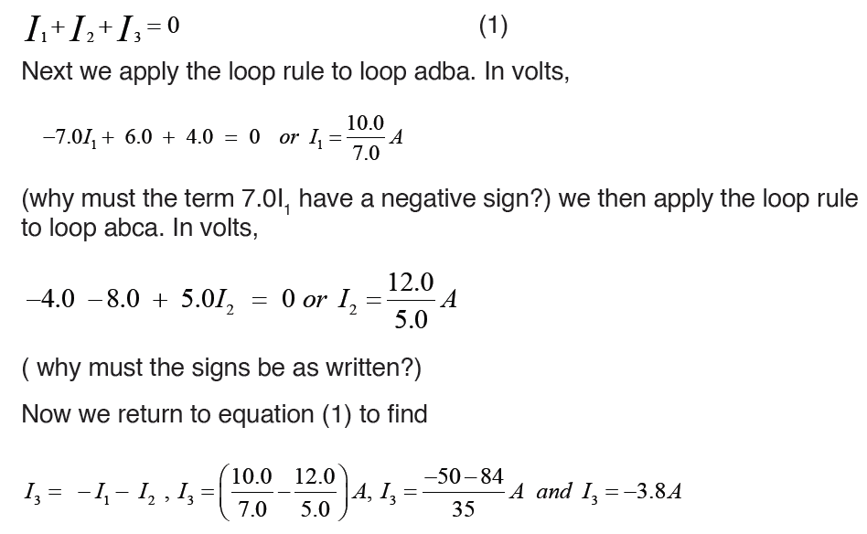
figure.
Example 2: The circuit shown in figure below contains two batteries, each
with an emf and an internal resistance, and two resistors. Find (a) the current
in the circuit (magnitude and direction); (b) the terminal voltage of the 16.0V battery; (c) the potential difference of a with respect to point c.
Solution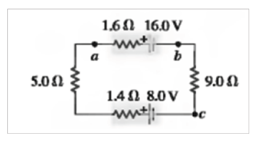
(a) The current is counterclockwise, because the 16 V battery determinesthe direction of current flow.
Example 3: In figure below, the battery has an internal resistance of 0.7Ω .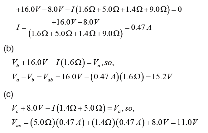
Find
i. the current drawn from battery,
ii. the current in each resistor,iii. The terminal voltage of the battery.
Solution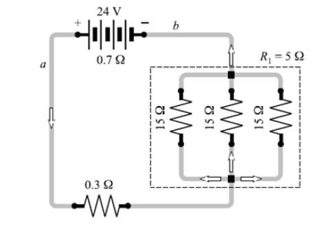
i. For parallel group resistance we have
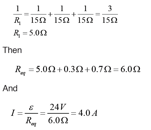
Method 2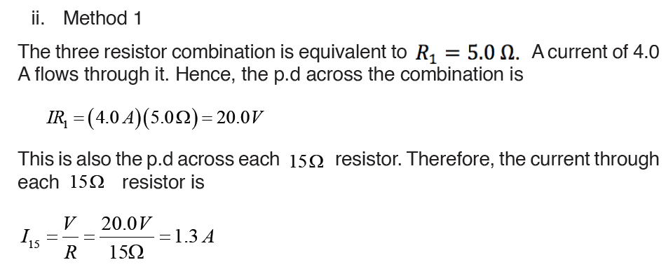
In this special case, we know that one – third of the current will go througheach resistor. Hence
Application activity 8.5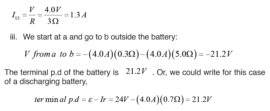
In the circuit below, each cell has e.m.f of 1.5 V and zero internal resistance.
Each resistor has a resistance of 10Ω . There are currents I1 and I2 in thebranches as shown.
(a) Use Kirchhoff’s first law to write down an expression for the current in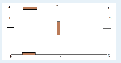
BE, in terms of I1 and I2
(b) Use Kirchhoff’s second law to write down equations for the circuit loops
i) ABEFA ; ii) CBEDCNote that you are not required to solve these equations.
SKILLS LAB
Conduct a survey to find out how people construct electric circuits and apply
Kirchhoff’s laws in analysis of complex electric circuits before installation
process.
Collect and analyze data about when, where, and why people use
Kirchhoff’s laws in dealing with complex electric circuits.
To complete this project you must
• Develop a survey sheet about electric components, demonstration of
Kirchhoff’s laws and complex electric circuit.
• Distribute your survey sheet to other student-teachers, family
members and neighbors.
• Compile and analyze your data.
• Create a report to display your findings in your sheet.
Plan it! To get started, think about the format and content of your survey
sheet. Brainstorm what kinds of questions you will ask. Develop a plan for
involving student-teachers in your class or other classes to gather more
data.
End unit assessment 8
1. State Kirchhoff Current Law and Kirchhoff Voltage Law
2. Distinguish between electric sources of currents from receptors.3. Find the current across the 10V battery
4. The figure below shows four resistors connected in a circuit with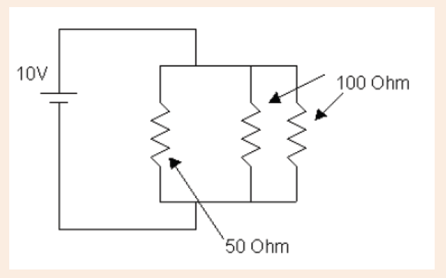
a battery. Which of the following correctly ranks the potentialdifference, ΔV , across the four resistors?
5. Determine the values of the the current flowing through each of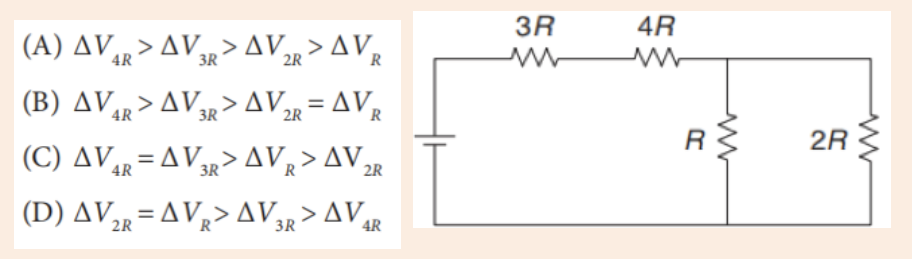
the resistors.