General
- Physics S4 SB File Uploaded 25/01/22, 11:19
- Physics S4 TG File Modified 25/01/22, 11:36
Unit 1: Thin lenses
LIGHT Thin Lenses

Key unit Competence
By the end of this unit, the learner should be able to explain the properties of lenses and image formation by lenses.
My goals
By the end of this unit, I will be able to:
* explain physical features of thin lenses
* state the types of lenses and explain their properties
* differentiate between lenses and curved mirrors
* explain the phenomenon of refraction of light by lenses
* construct the ray diagrams for formation of images by lenses
* explain the defects of lenses and how they can be corrected
* describe the daily applications of lenses
Introduction
Observe and think
Look at yourself in a flat mirror and choose one of the following that identifies your observation;
a) my image is clearly seen without changes.
b) my image shows some changes.
What do you think
a) What do you think about formation of your image by the mirror?
b) What are the characteristics of this image formed?
Key concept
Image formation through a mirror.Discovery activity
a) Look through a plain glass window and observe what happens. Discuss with your neighbor on what is observed.
b) Look through an open window and discuss with your neighbor about the observations.
c) Compare the observations in part (a) and (b) above.
d) Look through the lenses and describe the nature of image formed.
What I discover
Just curved mirrors change images, certain transparent medium called lens alter what you see through them.
A lens is a transparent medium (usually glass) bound by one or two curved surfaces. Different lenses give various natures of images depending on their characteristics.
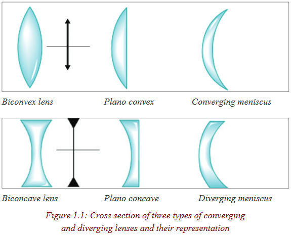
Types of lenses and their characteristics
A lens is a piece of glass with one or two curved surfaces. The lens which is thicker at the centre than at the edges is called a convex lens while the one which is thinner at its centre is known as a concave lens. The curved surface of the lens is called a meniscus. The lens in the human eye is thicker in the centre, and therefore it is a convex lens
Activity 1
Required Materials
• Notebook
• 2 convex lenses
• 2 concave lenses
• Flashlight or a torch bulb
• White paper
Procedure
1. Look closely at the lenses and answer these questions in your notebook:
a. How are the lenses shaped?
b. How are the lenses alike?
c. How are the lenses different?
2. Look through the lenses at the pages of a book, your hands, a hair, and other things. Draw what you see in your notebook and label each picture with the type of lens with which you observed the object. Be sure to answer the following questions:
a. How does a concave lens make things look like?
b. How does a convex lens make things look like?
3. Lenses bend light in different directions. Shine a flashlight through the lenses onto a piece of white paper and then answer the following questions in your notebook:
a. In what direction do convex lenses bend light?
b. In what direction do concave lenses bend light?
4. Shine the flashlight through different combinations of lenses: two convex lenses, two concave lenses, one concave and one convex lens. Draw pictures of what you see and answer these questions:
a. What happens when you use multiple lenses at the same time?b. Can you use two different lenses to make things far away appear closer?
5. If you can, darken the room and place a convex lens between a sunlit window and a white piece of paper. Place the lens close to the paper and then slowly move the lens towards the window. Draw a picture of what you see in your science notebook.
Do you see that rays change the direction after the lens? How do the emergent rays from each of the lenses behave?
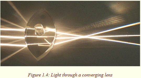
The light rays from the ray box change the direction after passing through the lens. They are therefore refracted by the lens. Hence, lenses form images of objects by refracting light.
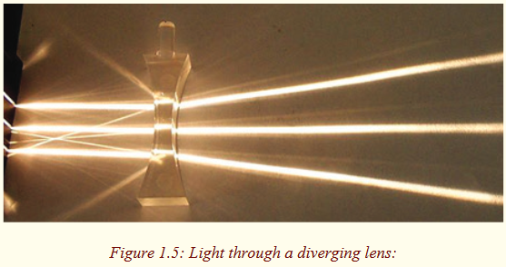
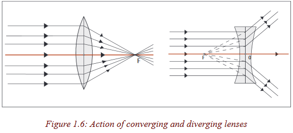
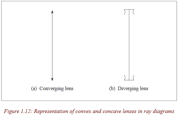
You can see that the rays from the convex lens are getting closer and closer to a point. The rays are thus converging, and hence a convex lens is called a converging lens. You can also see that the refracted rays from the concave lens are spreading out. This kind of lens is called diverging lens.
Summary:
1. A lens is a transparent medium (usually glass) bounded by one or two curved surfaces. There are two types of lenses; a convex lens also called a converging lens and a concave lens also known as a diverging lens.
2. A convex lens is the one which is thicker at the centre than at the edges. A concave lens is the one which is thinner at the centre than at the edges.The figure below shows three types of convex lenses and three types of concave lenses.
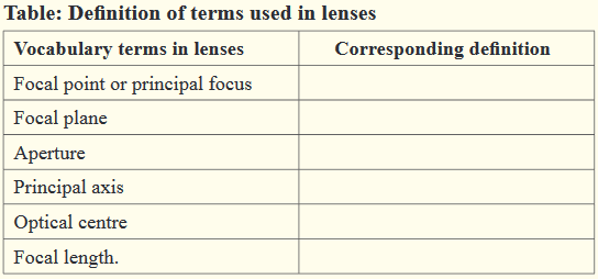
Terms used in lenses
Activity 2
(i) Place a convex lens on a white sheet of paper with its sharp edge perpendicular to the paper.
(ii) Draw two parallel lines each touching the apex of the lens.
(iii) Measure the length between the two lines. Write down in your notebook the comments about the length measured?
The length between the lines is the width of the lens. This width of the lens is called the aperture of the lens.
Activity 3
Place two similar Plano convex lenses together so that the two plane surfaces are in contact.Write down in your notebook your observation.
When do the two Plano convex lenses form a bi-convex lens? The two plane surfaces of the Plano convex lenses form a vertical line which divides the lens into two halves. This line is called the axis of the lens.
Activity 4
(i) You have learned about symmetry in secondary mathematics. How many lines of symmetry does a convex lens have?
(ii) Place a convex lens on a white sheet of paper and perpendicular to it, draw its outline.
(iii) Draw its lines of symmetry.
(iv) Where do these lines meet?
(v) Repeat the above steps ii) and iii) but with a concave lens.
Discuss in your group and write down in your notebook the observation.
Lenses have two lines of symmetry, a vertical line and a horizontal line. The vertical line is called the axis of the lens (already seen in activity 2). The horizontal line is known as the principal axis of the lens.
Notice that these lines meet at a point. This point is the centre of the lens, called the optical centre of the lens denoted by O.
Activity 5
(i) Place a convex lens on a white sheet of paper and draw its outline.
(ii) Produce the outlines so as to make spheres from which the lens was cut.
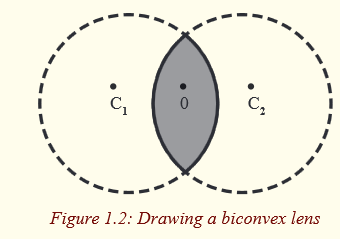
(iii) Note the centres C1 and C2 of the spheres formed.
(iv) Join the two centres of the spheres.
(v) Measure the distance between each centre and the optical centre.
What do you notice about the measured distance?
Can you see that the distances, OC1 and OC2 are equal?
Repeat the same but with a concave lens.
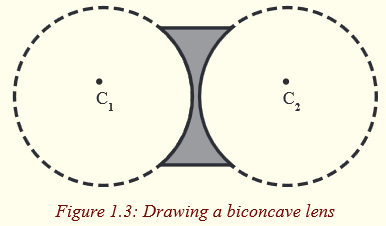
Do you see that the concave lens is not part of the spheres? Discuss with your neighbour and write in your notebook the observation.
The centre of each sphere is called the centre of curvature of the surface of a lens and the distance from the centre of curvature to the optical centre is the radius of curvature of the surface. Since the convex lens forms part of the spheres, its centre of curvature is real and hence its radius of curvature.
Activity 6
(i) Use a torch to produce several rays of light to shine on the convex lens.
(ii) Look at rays emerging from the lens.Can you see that the rays converge to a point? Which name do you give to this point? Write down the observation in your notebook.
Repeat the experiment but with the concave lens. Write down the observation in your notebook.
This point to which all parallel rays converge after refraction by a convex lens is called the principal focus of the convex lens.The rays emerge from the lens when they are spreading out.
They are diverged and appear to come from a point. This point from which the rays appear to diverge after refraction by the concave lens is the principal focus of the lens.Since rays converge to this point for the case of a convex lens, the principal focus of a convex lens is real.
The principal focus of a concave lens is virtual as the rays appear to come from it.Repeat the above experiments by changing the lenses so that their right sides become the left.
Do you see that the same thing happens for each?
Light can travel into the lens from the left or from the right. It therefore has two principal foci on both sides of the lens.The principal focus of a lens is also called the focal point of the lens, and it is denoted by F.
Activity 7
(i) Hold a convex in a lens holder so that the rays of light from a distant tree are focused on a white piece of paper by moving the paper to and fro from the lens.
(ii) Measure the distance from the lens to the sheet of paper.
Repeat the above experiment with a fatter lens.Does the fatter lens give a shorter focal length or a longer one?
Discuss on the observation and write short notes in your notebook.
Since the image forms where the refracted rays meet and because the rays from the distant tree are parallel, the piece of paper must then be at the principal focus of the lens. This distance from the lens to the image is the focal length of the lens. The focal length of the lens is thus the distance from the centre of the lens to the principal focus. It is always denoted by f.
The fatter lens has a shorter focal length, implying that the thicker the lens, the shorter the focal length and vice versa.
We have already seen that the lens has two principal foci.
It means that these principal foci are at equal distances on the opposite sides of the lens.Repeat the experiment with the concave lens.
What do you notice?
The image cannot be seen. This is because the concave lens has a virtual principal focus.
Activity 8
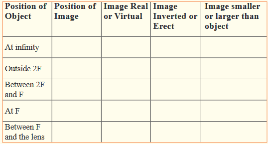
Read and interpret the sentences below and fill in the table redrawn in your notebook.
a) The distance between the edges of the lens.
b) The line through the optical centre at right angles to the lens or the line passing through the optical centre that joins the centers of curvature of the two surfaces of the lens.
c) A point on the principal axis to which all rays parallel and close to the axis converge in case of a convex lens or from which they appear to diverge in case of a concave lens after passing through the lens.
d) The distance from the optical centre to the principal focus of the lens.
e) A plane containing a focal point in which all parallel rays close to the axis converge or appear to diverge after refraction by the lens.
f) The center of the lens or point in which vertical line through the lens meets the principal axis.
Go Further
Visit the library and draw the diagrams in your notebook using convex and concave lenses. Indicate all terms defined in the table above on the diagrams.
Refraction of light through lenses
Lenses can be thought of as a series of tiny refracting prisms, each of which refracts light to produce an image. These prisms are near each other (truncated) and when they act together, they produce a bright image focused at a point.
Each section of a lens acts as a tiny glass prism. The refracting angles of these prisms decrease from the edges to its centre. As a result, light is deviated more at the edges than at the centre of the lens.
The refracting angles of the truncated prisms in a converging lens point to the edges and so bring the parallel rays to a focus.
The truncated prisms of the diverging lens point the opposite way to those of the converging lens, and so a divergent beam is obtained when parallel rays are refracted by this lens because the deviation of the light is in the opposite direction.
The middle part of the lens acts like a rectangular piece of glass and a ray incident to it strikes it normally, and thus passes undeviated.
Properties of images formed by lenses
Activity 9
(i) Hold a hand lens about 2m from the window. Look through the lens. (CAUTION: Do not look at the sun).
What do you see?
(ii) Move the lens farther away from your eye. What changes do you notice?
(iii) Now, hold the lens between the window and a white sheet of paper, but closer to paper.
(iv) Slowly move the lens away from the paper towards the window. Keep watching the paper.
What do you see?
What happens as you move the paper?
Do you see that an inverted image of trees outside is formed on the paper?
How do you think the image is formed?
Rays come from all points on the objects. Where these rays meet or appear to meet after refraction by the lens is the position of the image.
Activity 10
You are provided with a lamp, a convex lens of known focal length, a lens holder and a white sheet of paper.
(i) Arrange the apparatus as shown below to investigate different images formed when the object (lamp) is placed at different positions from the lens.
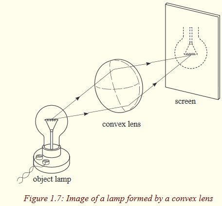
(ii) For each position of the object, move the screen (white sheet of paper) until you get a sharp image.
(iii) Fill in the table to show your results
Can you see that some images are larger than the object, some smaller and others same size as the object?
Do you notice that the images are inverted?
What do you notice when an object is between F and the lens?
Can you see that it is not seen on the screen?
Repeat the above experiment but with a concave lens of known focal length.
What do you notice in your observation?
Now, remove the screen and observe with the eye.
What do you notice?
Do you see that the image is small and upright (erect)?
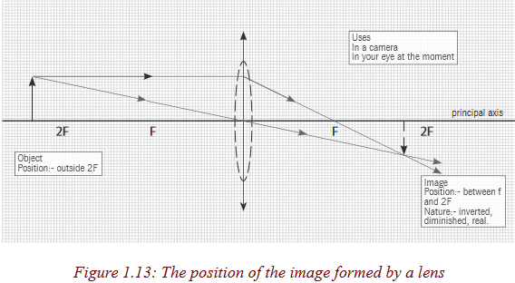
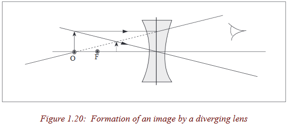
Notice that an image cannot be seen on the screen irrespective of the position of the object.The nature of the image formed by a convex lens depends on the position of the object along the principal axis of the lens.The principal focus of a lens plays an important part in the formation of an image by a lens since parallel rays from the object converge to it, and thus, we consider points F and 2F when describing the nature of the images formed by the lens.
These images can be larger or smaller than the object or same size as the object. When an image is larger than the object, we say that it is magnified and when it is smaller, we say that it is diminished.
Images which can be formed on the screen are Real images. Because light rays pass through these images, real images can be formed on the screen. All real images formed by the convex lens are inverted.
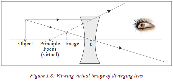
When an object is between F and the lens, there is no image formed on the screen. The image formed is not real and is only seen by removing the screen and placing an eye in its position. We say that it is a virtual image.
For a virtual image, rays appear to come from its position.Unlike for a convex lens where the nature of the image depends on the position of the object, a concave lens gives only an upright, small, virtual image, and is situated between the principal focus and the lens for all positions of the object.
Critical thinking:
1. Design an experiment to study images formed by convex lenses of various focal lengths. How does the focal length affect the position and size of the image produced?
2. Suppose you wanted to closely examine the leaf of a plant, which type of a lens would you use? Explain your decision.
Ray diagrams and properties of images formed by lenses
Activity 11
Shine on a convex lens in a dark room using a torch bulb. How many rays do you see emerging from the lens? Notice that the emergent rays are infinite
We have already seen that an image is formed where rays from the object meet. Rays come from all points on the objects. However, for simplicity, only a few rays from one point are considered when drawing ray diagrams. Where these rays meet or appear to meet after refraction by the lens is the position of the image.
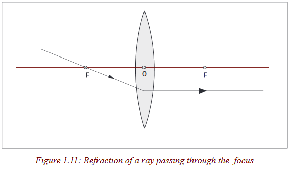
To locate the position of the image, two of the following three rays are considered.
1. A ray parallel to the principal axis which after refraction passes through the principle focus or appears to come from it.

2. A ray through the optical centre which passes through the lens undeviated (un deflected).
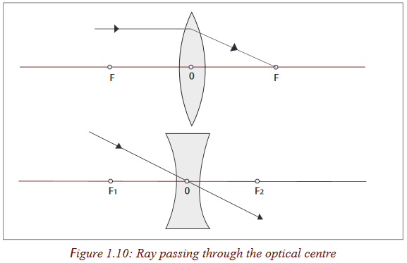
3. A ray through the principal focus which is refracted parallel to the principal axis.
The central part of a lens acts as a small parallel –sided block which slightly displaces but does not deviate a ray passing through it and for a thin lens, the displacement can be ignored.
In ray diagrams, a thin lens is represented by a straight line at which all the refraction is considered to occur. In reality, bending takes place at each surface of the lens.
Activity 12
(i) On a graph paper, draw a long horizontal line to represent the principal axis of the lens and a shorter line, at right angles to represent a thin lens.
(ii) Using 2cm to represent 10 units on both axes, mark the position of F on each side of the lens at 20cm from the lens. Also mark the points 2F at twice the focal length of the lens.
(iii) Mark the position of an object (pin), 20cm tall on the principal axis at a distance of 45cm from the lens.
(iv) Draw a line from the top of an object parallel to the axis that will pass through F after passing through the lens.(v) similarly, draw a line that passes through the centre of the lens.
(vi) Mark the position on the principal axis where the two lines meet.
(vii) Measure the distance of this position from the lens.
The position where the two lines meet is the position of the image.
Is the image inverted or upright?
The tip of the image is at the point where the two lines meet. Since the object is standing on the principal axis, the bottom of the image is also at the axis, hence the image is inverted.
Measure the height of the image (using the scales).
Is the image magnified or diminished?
Ray diagrams for a convex lens
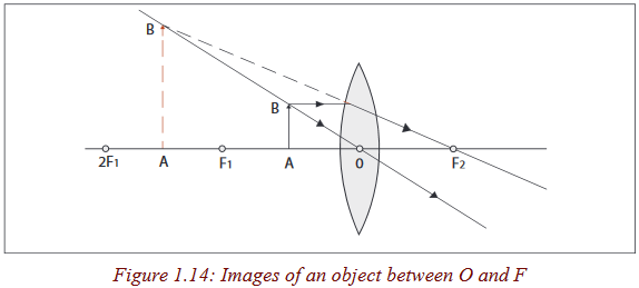
Object between the lens and F
Nature of image
The image is virtual, erect, larger than the object and behind the object.
Exercise
How is this lens useful when the object is in this position?
Object at F
Nature of image
The image is formed at infinity.
Exercise
Can you think of how useful is the lens when an object is at its focal point?
What is it?
Object between F and 2F
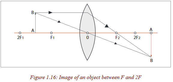
Nature of image
The image is real, inverted, larger than object (magnified) and beyond 2F.
Exercise
How is the lens useful when the object is in the above position?
Object at 2F
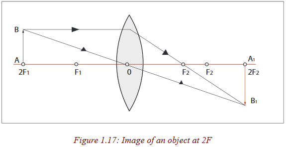
Nature of image
The image is real, inverted and same size as object.
Object beyond 2F
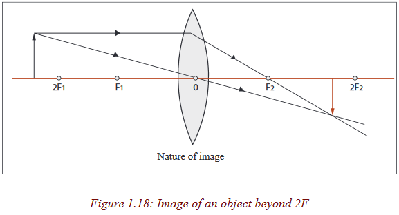
The image is real, inverted, smaller than object (dimensional) and is formed between F and 2F.
Discover
What can be a daily application of the lens when an object is in this position?
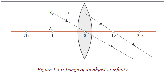
Object at infinity
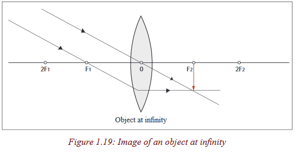
Nature of image
The image is real, inverted, smaller than object and is formed at F.When an object is between the lens and the principal focus, the rays from the object never converge, instead they appear to come from a position behind the lens. In this case, the lens is used as a simple magnifying glass because it forms an upright and magnified image (Figure 1.14).
When an object is at the principal focus of the lens, refracted rays emerge from the lens parallel to each other, and the lens is used as a search light torch, and theatre spotlights (Figure 1.15).
Figure 1.16 shows that when an object is between F and 2F, the lens forms a magnified real image. In this case, a lens is used as a film projector.
When an object is beyond 2F (Figure 1.18), a lens forms real and small image. The lens is used as a camera because this small, real image can be formed on a piece of film.
Accurate construction of ray diagrams
Problems for locating the position of the image can be solved by constructing a ray diagram as an accurate scale drawing on a graph paper.
Activity 13
An object 2cm high stands on the principal axis at a distance of 9cm from a convex lens. If the focal length of the lens is 6cm, what is the nature, size and position of the image.
Scale: Let 1cm on the paper represent 2cm of actual distance.
Example
1. An object is placed 40cm away from a diverging lens of focal length 20cm. If it is 2cm high, determine graphically the position, size and nature of the image.
2. Let 1cm on the paper represent 10cm on the horizontal axis and 1cm on the vertical axis of the actual distance.
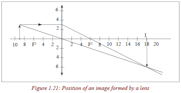
It is 4cm high and is formed at 18 cm from the lens.
The image is virtual, erect, 0.7cm tall and is formed at 13cm from the lens on the same side as the object.
The thin lens formula
Activity 14
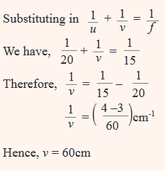
Using the same question in the above activity (13), find the position of the image v for an object at a distance u infront of a convex lens of focal length f , using the formula

What value of the image distance have you got?
Compare the value obtained with the one obtained from a ray diagram.
What do you notice in accordance to your observations?
Activity 15
(i) Draw a ray diagram to determine the nature and position of the image of an object placed 10cm from a diverging lens of focal length 15cm.
(ii) Using the above information, find the nature and position of the image using a lens formula. (assign f a negative sign during your substitution).
What is the location of the image?
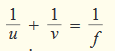
The lens formula gives the relationship between the object distance, u, image distance, v, and the focal length, f of the lens.
This relation is given by

Where u is the distance of the object from the lens,v the image distance and fthe focal length of the lens
The sign convention
From activity 13, we notice that all the distances are measured from the optical centre and in activity 14, we substituted for u, v and f using positive numerical values. It therefore follows that distances of real images and real principal focus are positive.
In activity 14, then you will notice that the image distance from the lens is negative but equal to the distance determined graphically. This distance is obtained by using a negative numerical value of the focal length. Since a concave lens has a virtual principal focus, and forms virtual images, distances of virtual images and virtual principal foci are negative.
Sign convention states that real is positive while virtual is negative. This should be put under consideration when one is using the lens formula to solve problems.
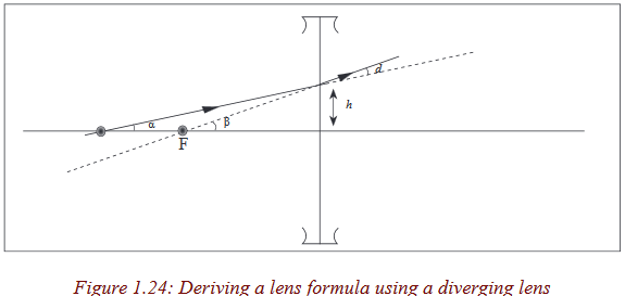
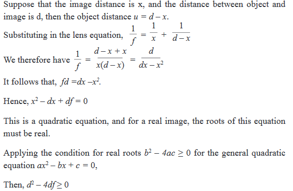
Derivation of the lens formula Convex lens
Consider a point object O on the principal axis, at a distance, u greater than the focal length from the lens. Suppose that a ray from O is incident on the lens at a small height h above the axis and is refracted to form an image I at a distance v from the lens.

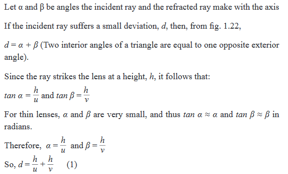
Now consider a ray from a finite object parallel to the principal axis and incident on the lens at the small height, h. After refraction, this ray passes through the focal point, F, a distance, f, from the lens.
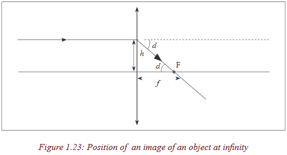
This incident ray suffers the same deviation, d, as above since the lens is considered as a small angle prism and all rays entering a small angle of prism at small angles of incidence suffer the same deviation.
From the figure above, the deviation, d, is equal to the angle the refracted ray makes with the axis (alternate angles)

Concave lens
Consider a point object O on the principal axis of the diverging lens at a distance, u, so that its image is formed at a distance, v.
Let angles α and β be the angles made by the incident and refracted rays with the axis respectively.
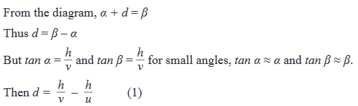
Now consider a ray from a finite sized object parallel to the axis. This ray appears to come from the focal point F after refraction.
If we introduce the “real is positive” sign convention, the focal length of the diverging lens is negative and the distance v in equation (1) is also negative since it’s a virtual image.

Magnification
Activity 16
(i) Using the same drawing in activity 15, measure the heights of the object and the image respectively.
(ii) Find the ratio of the image height to the object height.
(iii) How many times is the image larger than the object?
(iv) Now, find the ratio of the distance of image from the lens to the distance of object from the lens.
(v) Compare the two ratios.
What do you notice in accordance to your observation?
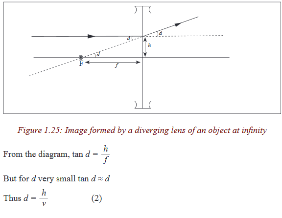
You can notice that the ratio of image height to object height is equal to that of image distance to object distance from the lens. This ratio is called Linear magnification of the image. It tells us the number of times the image is larger than the object. It is sometimes called Lateral or transverse magnification.
Thus, the lateral, transverse or linear magnification of an image produced by the lens is the ratio of image size to the object size or image distance to object distance.

consider a ray from a finite object at a distance u through the optical centre of a converging lens passing through a point I, the position of an image at a distance v.
Applications of the lens formula

Example
An object is placed 20cm from a converging lens of focal length 15 cm.
Find the nature, position and magnification of the image.The object is real and therefore u = + 20cmSince the lens is converging, f = + 15cm
Exercise
1. An object is placed 12cm from a converging lens of focal length 18 cm. Find the nature and the position of the image.
2. Find the nature and position of the image of an object placed 15cm from a diverging lens of focal length 15cm. Critical thinking exercise From the magnification formula and the lens formula, show that the image distance v can be related to the focal length of the lens by m

Least possible distance between object and real image with converging lens
Activity 17
You are provided with a convex lens of known focal length, a pin and a white screen.
(i) Place an object (pin) in front of a concave lens at a distance greater than the focal length.
(ii) Place the screen on the other side of the lens and move it to and fro until a clear image is seen.
(iii) Measure the distance between the object and the screen.
(iv) Repeat the above procedures for other values of object distance.
(v) Compare the corresponding distances between the object and the image with the focal length of the lens.
(vi) Are the distances between corresponding objects and images greater than four times the focal length of the lens?
(vii) Discuss in your groups and write short notes in your notebook.
Experiments show that it is not always possible to obtain a real image on a screen although the object and the screen may both be at a greater distance from a converging lens than its focal length.
Theory shows that the minimum distance between the object and the screen for an image to be formed is four times the focal length, f. Therefore, the distance between an object and a screen must be equal to or greater than four times the focal length.
Consider a point object O on the principal axis of a converging lens forming an image I.
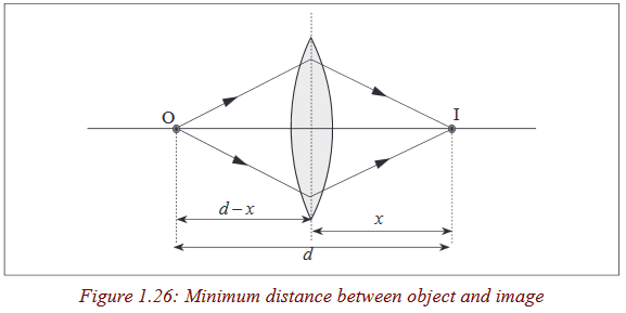

Thus the distance d between the object and the screen must be greater than or equal to 4f otherwise no image can be formed on the screen.
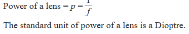
Power of the lens
Activity 18
(i) Focus a distant object through the window with a thin lens.
(ii) Note the distance of the screen from the lens.
(iii) Repeat the above procedures with a thicker lens.
(iv) Compare the distances of the images formed for each case.
Do you notice that the image formed by the thicker lens is nearer to the lens than that formed by the thinner one?
Discuss and write short notes in your note book.
Since the image formed by the thicker lens is nearer, the thicker lens is more powerful than the thinner lens of the same material.We have already seen that an image of a distant object forms at the focus of the lens and the thicker the lens the shorter the focal length.
So the power of the lens depends on its focal length, that is, as the focal length becomes shorter, the power increases.The power of the lens is defined as the reciprocal of its focal length in metres.
Quick activity
1. Calculate the power of the lens of focal length of 15 cm.2. A converging lens has a power of 0.02D, what is its focal length?
Determination of the focal length of the lens
Converging lens
Rough method
Activity 19
(i) Place a converging lens on a table while facing a window.
(ii) Place a white screen behind the lens.Move the screen to and fro (forwards and backwards) until a sharp image of a distant object is seen on the screen.
Discuss and write down the observation in your notebook.Measure the distance from the lens to the screen.
The distance from the lens to the screen is the focal length of the lens since rays from a distant object strike the lens when they are parallel.
Graphical determination of focal length of a convex lens
Activity 20
You are provided with a lamp, a screen with cross wires, a convex lens, a lens holder and a white sheet of paper
(i) Set up the lens in front of an illuminated object at a given distance u=15cm and adjust the screen until a sharp image is seen.
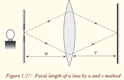
ii) Measure the distance, v from the lens to the screen.
(iii) Repeat the above for values of u = 20cm, 25cm, 30cm, 35cm, 40cm and 45cm.
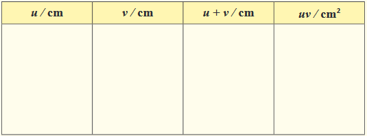
(iv) Record your results in a suitable table including values of uv and u + v.
(v) Plot a graph of uv against u + v.
(vi) Find the slope (gradient), of the graph.

The above expression is an equation of a line and hence a graph of uv against u + v is a straight line passing through the origin and its slope is the focal length f of the lens.
Instead of using an illuminated object, a pin may be set up in front of the lens so that it forms a real image on the opposite side whereby the position of this image can be located by the help of a search pin using the method of no-parallax.
Diverging lens
Determination of focal length of a diverging lens by Concave mirror method
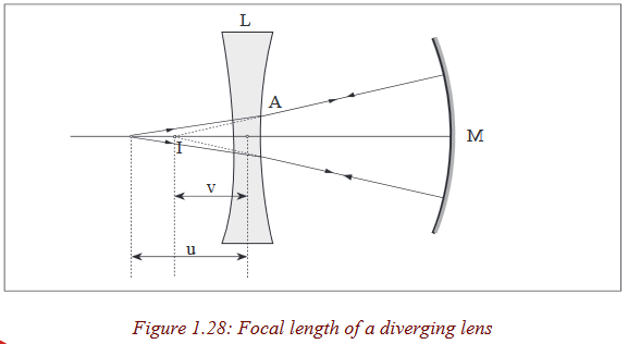
Activity 21
You are provided with a concave lens, concave mirror of known radius of curvature, a screen with cross wires and a lamp.
(i) Place an object in front of a concave lens (diverging lens) at a measurable distance from the lens.
(ii) Place a concave mirror behind the lens so that a diverging beam is incident on it.
(iii) With the object and the lens in position, move the mirror to and fro until an image coincides with the object.
(iv) Measure the object distance.
(v) Measure the distance between the lens and the mirror, Lm.
(vi) Calculate the image distance v from the lens v = r – Lm, where r is the radius of curvature of the mirror.
(vii) Find the focal length of the lens using
Discuss on the observation and write short notes in your notebook.
We have already seen that a concave lens forms virtual images of real images which cannot be seen on the screen. So, to determine the focal length of a diverging lens, we need to form a virtual object for the diverging lens so that a real image is produced. This is achieved in the experiment by putting a concave mirror behind the lens so as to reflect back the diverging rays from the lens.
As you saw in your lower secondary classes, when an object is placed at the principal focus of a concave mirror, the image is formed at the same position with it. Now, since the object and its image are coinciding, it means that they are at the centre of curvature of the mirror; v is negative as I is a virtual image for the lens, and as the object and image are coincident, the rays must be incident normally on the mirror M. Thus, reflected rays from the mirror pass through its centre of curvature which is the position of the virtual image
Combination of lenses
Activity 22
Have you ever critically looked at the microscope?
Look at the microscope provided and count the number of lenses it has.How many lenses have you seen?
In our next unit, we shall talk about instruments which use lenses to focus objects. Among others, a microscope uses a combination of two lenses to focus objects.
Effective focal length of a combination of lenses
Activity 23
a) (i) Focus a distant tree through a window using a convex lens onto a white sheet of paper.
(ii) Measure the distance from the lens to the paper.
b) (i) With the convex lens still in position, place another convex lens similar to the above besides and in contact with it.
(ii) Move the paper to and fro until a clear image of the tree is focused on it.
(iii) Measure the distance from the lenses to the white sheet of paper.
Since the rays from a distant tree are parallel, they meet at the focal plane of the lens (in a) and of the combination of the lenses (in b).
Therefore, the distance from the lens to the white sheet of paper is the focal length of the lens (in a) and the distance from the combination of the two lenses to the screen is the focal length of the combination.
From the above activity, let the focal length of the individual lenses be f1 and f2 respectively.
Substitute the values the focal lengths obtained from the a experiment in the equation
where F is the focal length of the combination.What do you notice?
Can you see that the left hand side of the equation is equal to the right hand side?
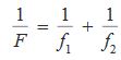
The focal length of a combination of lenses in contact is obtained from the relation,
Note that sign convention still holds for the focal lengths of the lenses during substitution of the numerical values in the formula.
Exercise:
Find the focal length of a combination of a converging lens and a diverging lens of focal lengths 5cm and 10cm respectively.
Derivation of the expression of effective focal length of the lens combination. The focal length, fof a combination of two thin lenses of focal lengths f1 and f2 respectively can be found by considering a point object O placed on the principal axis of the lenses in contact.
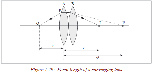
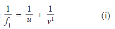
In the absence of lens B, ray OP would pass through point I1 which would be a real image of lens A.If u is the object distance and v1 is the image distance, then from the lens formula;
It follows that
With lens B in position, II acts as a virtual object for this lens forming an image at I.This means that for lens B, the object distance is –v1and the image distance is v.
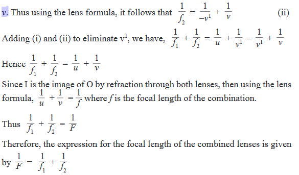
This formula applies to any two thin lenses in contact, such as two converging lenses, or a converging and diverging lens. When the formula is to be used, the sign convention must be applied.
Example
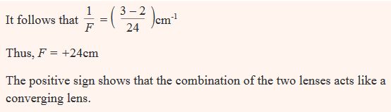
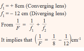
A thin converging lens of focal length 8cm is placed in contact with a diverging lens of focal length 12cm. Calculate the focal length of the combination.
Exercise
1. An object O is placed 12cm from a thin converging lens P of focal length 10cm and an image is formed on a screen S on the other side of the lens. A thin diverging lens, Q is now placed between the converting lens and S, 50cm from the converging lens. Find the position and nature of the final image if the focal length of the diverging lens is 15cm.
2. An object is placed 6.0cm from a thin converging lens A of focal length 5.0cm. Another thin converging lens B of focal length 15cm is placed co-axially with A and 20cm from it on the side way from the object. Find the position, nature and magnification of the final image.
Defects of lenses and their corrections
Activity 24
(i) Place a white sheet of paper on a horizontal ground.
(ii) Hold a glass ruler above the paper so as to focus rays from the sun on to the paper.
(iii) Observe carefully the image formed on the sheet of paper.
(iv) Repeat the above with the convex lens.What have you observed?
Share the ideas about the observations.
Notice that the image has coloured patches.
This defect where by an image formed has coloured patches is called chromatic aberration.
There are two kinds of defects; spherical aberration and chromatic aberration.
Spherical aberration
This arises in lenses of larger aperture when a wide beam of light incident on the lens, not all rays are brought to one focus. As a result, the image of the object becomes distorted. The defect is due to the fact that the focal length of the lens for rays far from the principal axis are less than for rays closer to a property of a spherical surface and as a result, they converge to a point closer to the lens.
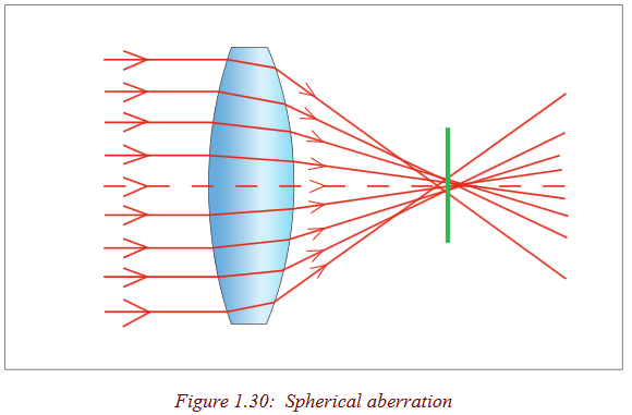
This defect can be minimised (reduced) by surrounding the lens with an aperture disc having a hole in the middle so that rays fall on the lens at a point closer to its principal axis. However, this reduces the brightness of the image since it reduces the amount of light energy passing through the lens.
Chromatic aberration
This occurs when white light from an object falls on a lens and splits it into its component colours. These colours separate and converge to different foci, and this results into an image with coloured edges.
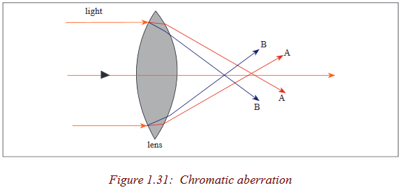
The separation takes place because the material of a glass of a lens has different refractive indices for each colour. The colours travel at different speeds in glass: red colour with the greatest and the violet with the least. As a result, violet is deviated most and red is the least deviated
Thus, a converging lens produces a series of coloured images of an extended white object as shown in the figure above (exaggerated for clarity).
Chromatic aberration can be minimised by using an achromatic lens called an achromatic doublet. This consists of a converging lens of crown glass combined with a diverging lens of flint glass cemented together with Canada balsam.
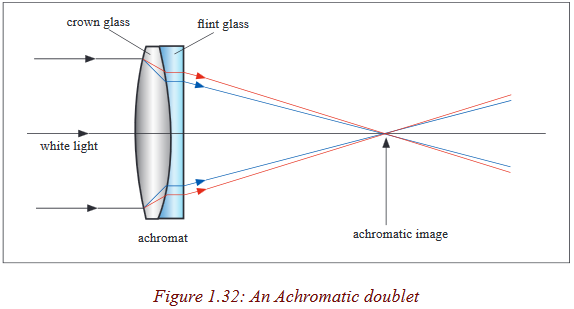
The flint glass of the diverging lens produces the same dispersion as the crown glass of the converging lens but in the opposite direction and the overall combination is converging. As a result, the achromatic combination converges the white light to one focus.
Activity 25
Disscuss with your neighbour the applications of lens combinations in daily lives and write short notes in your notebook.
Refraction through prisms
Activity 26
Problem
Have you ever heard of a prism?How does it look like?
Procedures
a) Consider the shapes of the glasses provided below.
Observe them clearly and identify the shape of a prism.
Explain your reasoning in your notebook.
b) With the help of a teacher, have different shapes of glasses. Touch, observe and identify the real shape of the prism.
c) Examine the features of the one selected as a prism. Discuss them with your neighbour and write them in your notebook.
In optics, a prism is transparent material like glass or plastic that refracts light. Atleast two of the flat surfaces must have an angle less than 90o between them. The exact angle between the surfaces depends on the application.
Terms associated with refraction through prism
Activity 27
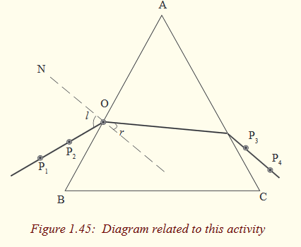
(i) Place a glass prism on a white sheet of paper fixed on a soft board and mark its outline ABC.

(ii) Remove the glass prism and measure an angle between two slanting faces of the prism.
(iii) Draw a normal line ON, and draw a line making a given angle with the normal.
(iv) Place the glass prism back in its outline and stick two pins, P1 and P2 in the paper along the line. While looking through the prism through face AC, stick pins P3 and P4 in the paper exactly in line with image, I1 and I2 of the pins, P1 and P2.
(v) Remove the prism and join points P3 and P4 .
(vi) Join point O to the point where the line through P3 and P4 meets face AC.
(vii) Discuss the observations through presentations.
What name can you give to the angle between the line passing through pins P1 and P2 and the normal ON?
What do you think is the name of an angle between the normal ON and the line from the point where the line through P3 and P4 meets face AC?
What is the name of the line that passes through P3 and P4?
What do you think is the name of an angle between the line passing through P3 and P4 and the normal to AC?
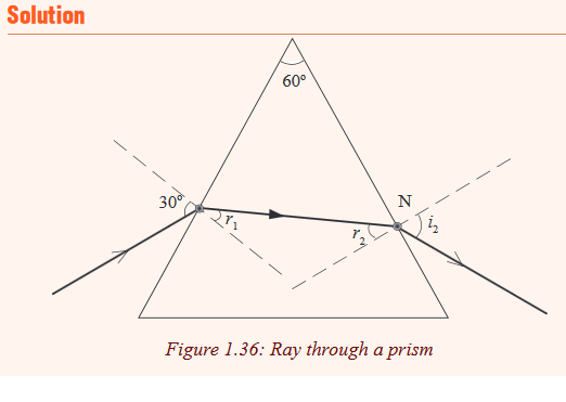
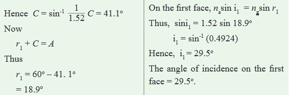
Angle A: This is called refracting angle or angle of the prism. It is the angle between the inclined surfaces of the prism
.Angle i; This is the angle of incidence on the first face of the prism.
Angle r1; This is the angle of refraction on the first face of the prism.
Angle r2; This is the angle of refraction on the second face of the prism.
Angle l2 ; This is the angle of emergence from second face of the prism. Sometimes this is denoted by letter e.
General formulae for the prism
Activity 28
In groups of four, use geometry of the above drawn figure and derive the relation r1 + r2 = A.
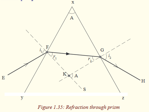
In the figure, E F is a ray incident on the refracting surface YX of the prism X Y Z from air and then to air from surface XZ of the prism. KF and KG are normals at the points of incidence and emergence of the ray respectively.

The position and shape of the third side of the prism does not affect the refraction under consideration and so is shown as an irregular in Fig.
Example
A ray of light falls from air to a prism of refracting angle 60o at an angle of 30o. Calculate the angle of emergence on the second face of the prism (Take refractive index of the material of glass, ng = 1.5).
Example
A prism of refracting angle of 67o and index of refraction of 1.6 is immersed in a liquid of refractive index 1.2. If a ray travelling through a liquid makes an angle of incidence of 53o. Calculate the angle of emergence of the ray from the second face of prism.

Exercise
A ray of light incident from air to a prism of refracting angle 60o grazes the boundary on the second face of the prism. Find the angle of incidence of the ray on the first face. (Take ng = 1.52).
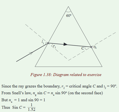

Deviation of light by a prism
Activity 29
Have you ever heard of the word deviation?List down in your notebook atleast two ways in which light can be deviated.
Light can be deviated by reflection and refraction. Since a prism refracts light, it therefore changes its direction.
Activity 30
You are provided with a glass prism of refracting angle 60o, four optical pins, a white sheet of paper, a soft board and fixing pins.
(i) Place a prism on a white sheet of paper and mark its outline ABC.

(ii) Remove the prism and draw a normal line ON to face AB and draw a line making an angle of 10o to ON to represent the incident ray.
(iii) Place back the prism in its outline and fix pins P1 and P2 along the line.
(iv) While looking through the other face AC of the prism, fix pins P3and P4 so that they appear in line with images of P1 and P2.
(v) Remove the prism and draw a line through P3 and P4 on to face AC of the prism.
(vi) Measure the angle of deviation d.
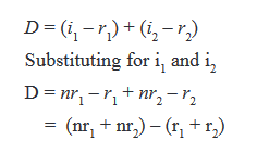
A prism deviates light on both faces. These deviations do not cancel out as in a parallel sided block where the emergent ray, although displaced, is parallel to the incident ray surface. The total deviation of a ray due to refraction at both faces of the prism is the sum of the deviation of the ray due to refraction at the first surface and its deviation at the second face.
Let d1 and d2 be angles of deviation at the first and second faces of the prism respectively.
Total deviation D = d1 + d2
Angle of deviation at the first face, d1 = i1 – r1 and the angle of deviation at the second face, d2 = i2 – r2
Thus D = i1 – r1 + i2 - r2 = (i1 + i2) – (r1 + r2)
But r1 +r2 = A
Therefore D = (i1 + i2) – A
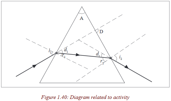
Angle of minimum deviation and determination of refractive index n of a material of the prism
Activity 31
(i) Place a prism on a white sheet of paper and mark its outline ABC.
(ii) Remove the prism and draw a normal line ON, and then several lines at different angles to ON to represent the incident rays.
(iii) Place the prism back in its outline and fix pins P1 and P2 along one line.
(iv) While looking through the other face AC of the prism, fix pins P3and P4 in such a way that they appear in line with images of P1 and P2.
(v) Remove the prism, and draw a line through P3 and P4 .
(vi) Measure angle of deviation d of the ray.
(vii) Repeat the above procedures for other values of i
(viii) Record your values in a suitable table.

(ix) Plot a graph of deviation d against angle of incidence.
The graph is a U-curve and its minimum value corresponds with the angle of minimum deviation. So Dmin can be read from the deviation axis.
Experiment shows that as the angle of incidence i is increased from zero, the deviation begins to decrease continuously to some minimum value Dmin and then increases to a maximum as i is increased further to 90o.
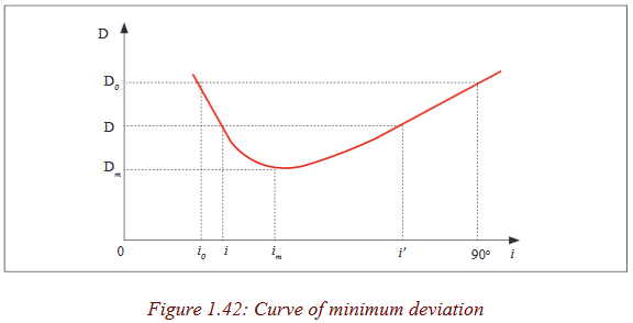
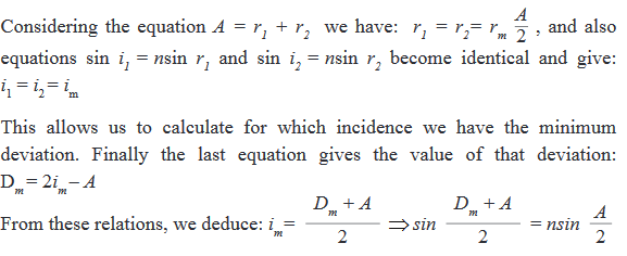
From the variation fig 1.41 above, there is one angle of incidence which gives a minimum deviation. The experiment shows that this minimum deviation occurs when the angle of emergence is exactly equal to the angle of incidence and the two anternal angles of refraction are equal. At this value, a ray passes symmetrically through the prism and the ray inside the prism is perpendicular to the directing plane, see figure 1.42.
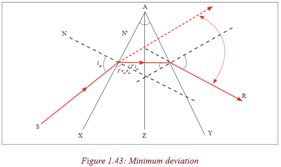

Angle of minimum deviation and the refractive index n of the material
Experimentally, it is shown that when the angle of incidence increases, the deviation decreases, passes at a maximum then increases.When the deviation is minimal, the angles of incidence and emergence are equal.
Example
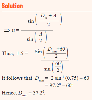
A glass prism of refracting angle 60o has a refractive index of 1.5. Calculate the angle of minimum deviation for a parallel beam of light passing through it.
Exercise
A glass prism of refracting angle 72o and index of refraction 1.66 is immersed in a liquid of refractive index 1.33. What is the angle of minimum deviation for a parallel beam of light passing through the prism?
Deviation of light by a small angle prism
Consider a ray incident almost normally in air in a prism of small refracting angle A (less than about 60 or 0.1 radian) so that the angle of incidence i is small.

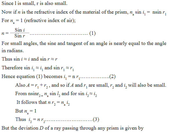
The expression D = A (n – 1) shows that for a given angle A, all rays entering a small angle prism at small angles of incidence suffer the same deviation.
Example Light is incident at a small angle on a thin prism of refracting angle 5o and refractive index 1.52o. Calculate the deviation of the light by the prism.
For small angle prism, D= (n –1) A
n = 1.52 and A = 5
Thus D = (1.52 – 1)5.= 0.52 x 5 = 2.6o
Example
A mono chromatic light is incident on one refracting surface of a prism of refracting angle 60o, made of glass of refractive index 1.50. Calculate the least angle of incidence for the ray to emerge through the second refracting surface.
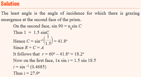
So the least angle of incidence for a ray to emerge on the second face of a 60oprism of refractive index 1.5 is 27.9o.
Determination of refractive index of a material of a prism
Activity 32
(i) Place a glass prism on a white sheet of paper fixed on a soft board and mark its outline ABC.
(ii) Remove the glass prism and draw a normal line ON, and several lines at different angles to ON to represent incident rays.
(iii) Place the glass prism back in its outline and stick two pin P1 and P2in the paper along one of the lines drawn to represent an incident ray. While looking through the prism through face AC, stick pins P3 and P4in the paper exactly in line with image, I1 and I2 of the pins, P1 and P2.
(iv) Remove the prism and join points P3 and P4 . This line represents the emergent ray.
(v) Join point O to the point where the line through P3 and P4 meets face AC. This ray represents the refracted ray.
(vi) Measure angle of refraction, r.
(vii) Repeat the above procedures for other values of i.
(viii) Record your results in a table including values of sin i and sin r.

(ix) Plot a graph of sini against sinr and find the slope of the graph.
(x) Discuss through group presentation about the graph obtained.
The graph is a straight line graph and the gradient represents the mean value which is the refractive index of the material.
Dispersion of light by a prism
Activity 33
(i) Place a plane mirror in a basin and then pour water into the basin
.(ii) Leave the water to settle and slowly place the basin on sunshine so that the plane mirror reflects the light rays from the sun on a white wall or iron sheet.
(iii) Observe what is formed on the wall( iron sheet).
Discuss with your group and write in your notebook about the observation.
Sunlight split into many colours when it fell into water. This process is called dispersion. Dispersion is the splitting of light into its component colours.
Activity 34
(i) Place a prism in the centre of a piece of paper so that its refracting surface is directly facing the windows in order to receive light from the sun.
(ii) Place a white screen on the far side of the prism so that the refracted rays hit it.
(iii) Observe what is formed on the screen.
(iv) In brief, write in your notebook the observation.
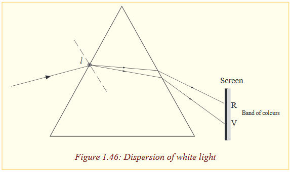
A band of seven colours is formed on the screen. The colours are in order of Red, orange, yellow, green, blue, indigo and violet (ROYGBIV) which are colours of rainbow. This band of colours is called a spectrum.
Thus, when a narrow beam of white light falls on a glass prism, it splits into a range of colours and these colours separate to form a spectrum, a process called dispersion. This occurs because white is not a single colour but mixture of all colours of the rainbow. The prism refracts each colour by a different amount because the colours travel at different speeds in the glass and thus the glass has different refractive indices for each colour.
The speed of a red colour is greatest and that of a violet colour is the least, and so the refractive index of a material of the prism for red colour is the least and that of the violet colour is the greatest. Now it follows that since the angle of incidence in air is the same for all the colours, red in deviated least by the prism and the violet rays are the most deviated as shown in the figure above (exaggerated for clarity because the colours overlap).
Applications of total internal reflection of light by a prism
Activity 35
(i) You are provided with a glass prism with angles measuring 45o- 45o-90o.
(ii) Place the prism on a sheet of paper and use a ray-box to shine in a ray of light as shown in the figure below.
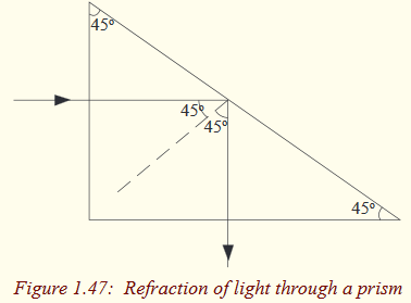
(iii) What do you notice about the phenomemenon above?
Notice that light goes straight through the first surface and when it meets the second surface, it is internally reflected. So, the long side of the prism acts as a mirror and turns light through an angle of 90o. Two prisms of the same type as above can be arranged in away and used in a periscope; an instrument used to see the top of an obstruction.
Use of prisms in periscopes
Activity 36
(i) Arrange two prisms provided and shine on one of the prisms using a ray box as shown below.
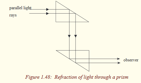
(ii) Discuss in your respective group about the phenomenon.
Light is tuned through 90o at each prism and it emerges parallel to the incident light. In prism periscopes, light from an object is turned through 90o at each prism ands reaches the observer at a different altitude to that of an object. So the image of the object is formed at another altitude but is same size as object.
Activity 37
(i) Place the same prism above on a piece of paper and use your ray box to shine on it as shown below.

(ii) What do you notice?
You can see that rays of light are turned through 180o.
An arrangement of two prisms each turning light through an angle of 180o is used in prism binoculars; instruments used to view hidden objects. This will be discussed in the next unit.
Critical Thinking Exercise
a) Give reasons why prism rather than plane mirrors are used in periscopes and prism binoculars.
b) Explain why diamonds are cut with their sides flat and others slanting.
In periscopes and prism binoculars, plane mirrors can be used but prisms are preferred because of the following reasons.
In the first place, a prism allows light to undergo total internal reflection and thus the images are formed by total internal reflection where as a mirror allows light to both reflect and refract at its surface. So for a prism, all the light
(100%) from the object is reflected but for a mirror some light is absorbed (about 95% is reflected) and thus a prism produces a brighter image than a mirror.
The silvering on the mirrors wears off with time but with prism no silvering is needed.Some mirrors, for example, thick plate mirrors produce multiple images of one object because of reflections and refractions at the surfaces and inside the glass but a prism produces anyone image.
Diamonds are cut that way so as to make use of total internal reflection. The multiple reflections inside diamond make it bright.
Exercises
1. A ray of light incident at an angle i on a prism of angle, A, passes through it symmetrically. Write an expression for the deviation, d, of the ray in terms of i and A. Hence find the value of d, if the angle of the prism is 60o and the refractive index of the glass is 1.48.
2. A beam of monochromatic light in incident normally on the refracting surface of a 60o glass prism of refractive index 1.62. Calculate the deviation caused by the prism.
3. a) Define the critical angle of a medium.
b) One side of a triangular glass prism put in a pool of water of refractive index 4/3 and the other side was left open to air. A ray of light from water was incident on the prism at an angle i = 21.7o. The light just grazes as it emerges out of the prism. Given that the refractive index of glass 1.52, determine the refracting angle A of the prism.
4. A monochromatic light is incident at an angle of 45o on a glass prism of refracting angle 70o in air. The emergent ray grazes the boundary of the other refracting surface of the prism. Find the refractive index of the material of glass.
5. A prism of diamond has a refracting angle of 60o. A ray of yellow light is incident at an angle of 60o on one face. Find the angle of emergence if the refractive index of diamond for yellow light is 2.42.
6. A ray of light just undergoes total internal reflection at the second face of a prism of refracting angle 60o and refractive index 1.5. What is its angle of incidence on the first face?
7. A sharp image is located 78.0mm behind a 65.0mm-focal-length converging lens. Find the object distance
(a) using a ray diagram,
(b) by calculation.
8. What is
(a) the position, and
(b) the size of the image of a 7.6cm high flower placed 1.00m from a 50.0mm focal length camera lens?
9. An object is placed 10cm from a lens of 15m of focal length. Determine the image position.
10. Two converging lenses A and B, with focal lengths fA=20cm and fB = -25cm, are placed 80cm apart, as shown in the figure (1). An object is placed 60cm in front of the first lens as shown in figure (2). Determine
(a) the position, and
(b) the magnification, of the final image formed by the combination of the two lenses.

11. Where must a small insect be placed if a 25cm focal length diverging lens is to form a virtual image 20cm in front of the lens?
12. Where must a luminous object be placed so that a converging lens of focal length 20cm produces an image of size four times bigger than the object (Consider the case of a real image and the case of a virtual)
13. From a real object AB we want to obtain an inverted image four times bigger than the object. We place a screen 5m away the object. Specify the kind, the position and the focus of the lens to use. Give the graphical and the algebraic.
14. In cinematography the film is located at 30m from the screen and the image has a magnification of 100. Determine the focal length of the lens used in projection.15. An object AB of 1cm is placed at 8cm from a converging lens of focal length 12cm. Find its image (Position, nature and the size).
16. An object of 2cm is placed at 50cm from a diverging lens of focal length 10cm. Determine its image.
17. An object located 32.0 cm infront of a lens forms an image on a screen 8.00 cm behind the lens.
(a) Find the focal length of the lens.
(b) Determine the magnification.
(c) Is the lens converging or diverging?
18. A movie star catches the reporter shooting pictures of her at home. She claims the reporter was trespassing. To prove her point, she gives as evidence the film she seized. Her 1.72m height is 8.25mm high on the film and the focal length of the camera lens was 210mm. How far away from the subject was the reporter standing?
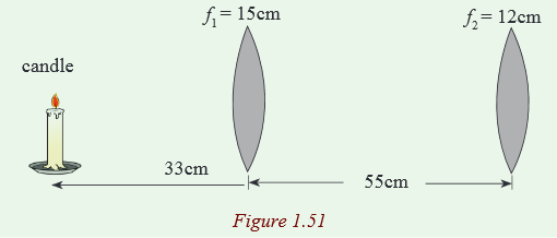
19. A lighted candle is placed 33cm in front of a converging lens of focal length f1=15cm, which in turn is 55cm in front of another converging lens of focal length f2=12cm. (a) Draw a ray diagram and estimate the location and the relative size of the final image. (b) Calculate the position and relative size of the final image.
20. When an object is placed 60cm from a certain converging lens, it forms a real image. When the objet is moved to 40cm from the lens, the image moves 10cm farther from the lens. Find the focal length of this lens.
21. A converging glass lens (n=1.52) has a focal length of 40.0cm in air. Find its focal length when it is immersed in water, which has an index of refraction of 1.33
.22. Verify that the focal length f of a symmetrical biconvex lens which the two faces have a radius of curvature R and refractive index 1.5 is fmeter=Rmeter.
23. We put in contact a converging lens of focal length 20cm and a diverging lens of focal length 50cm. What are the nature, the power and the focal length of the constituted lens?
24. To a converging lens of focal length 20cm we put in contact a second lens so that the constituted system has the power of 4 diopters. Determine the nature of the second lens and calculate the focal length.
25. In a physics lab students want to determine the focal length x of a thin diverging lens. They stick to it a converging lens of 5 diopters and they use the system to have a real and inverted image A’B’ of size equal to the one of the object AB. The distance from the object AB to the screen where they watch the image is 4m. Calculate x.
26. A thin glass lens n = 1.5 has a focal length +10cm in air. Compute its focal length in water n = 1.33.
27. A prism which has a refracting angle equals 60o and refractive index 1.5 receives a ray at an angle of incidence 45o; calculate the angle of emergence and the deviation of the ray.
28. Calculate for the same prism (Question 1) the value of minimum deviation as well as the value of i = i’.
29. Let consider a prism made in glass of refracting angle A=59o and the refractive index 1.52.
a) Calculate the deviation that makes an emerging ray with the extension of the incident ray for an incidence equal to 35o.
b) Calculate the angle of minimum deviation and specify the value of the angle of the corresponding angle of incidence and refraction inside the prism.
30. Given that a prism of refracting angle A = 60o and refractive index n=√331. Let consider a ray of light falling on a prism through an angle i=90o. If it goes out the prism through an angle i’, calculate i’.
32. Through what angle i must fall on the prism a ray to go out through an emergence i =90o.
33. Find the refractive index of a prism A = 60o producing a minimum deviation equal to 40o.
34. A triangular glass prism with apex angle 60.0° has an index of refraction of 1.50.
(a) Show that if its angle of incidence on the first surface is θ1 =48.6°, light will pass symmetrically through the prism,
(b) Find the angle of deviation Dmin for θ1 = 48.6°.
(c) What If? Find the angle of deviation if the angle of incidence on the first surface is 45.6°.
(d) Find the angle of deviation if θ1 = 51.6°.
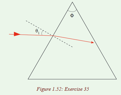
35. A triangular glass prism with apex angle Ф = 60.0° has an index of refraction n= 1.50. What is the smallest angle of incidence θ1 for which a light ray can emerge from the other side?
36. A triangular glass prism with apex angle Ф has index of refraction n. What is the smallest angle of incidence θ1 for which a light ray can emerge from the other side?
37. Place a triangular glass prism on a white sheet of paper and draw its outline.
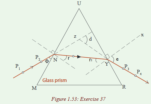
(i) Remove the prism and label the outline as MUR
(ii) Draw a perpendicular line to the face MU of the prism atN.
(iii) Draw a line TN so that it makes a relatively small angle with normal at N.
(iv) Replace the prism in its outline.
(v) Place pins P1 and P2 along TN and perpendicular to the paper.While looking through the other face UR of the prism, fix pins P3 and P4 so that they are in line with images of P1 and P2.
(vi) Remove the prism and draw a line through P3 and P4
.(vii) Repeat the above procedures with the same prism but turned upside down so that its refracting angle is facing upwards.What do you notice? Can you see that the rays are coming to a point?
38. Copy the diagram below and fill in the names and use of other optical instruments you know.

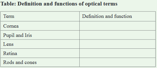
39. Use the concept obtained from unit 1 and write the definition and main function in the table below in your notebook.
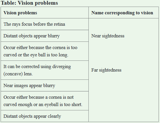
40. Match the following statements with corresponding name of vision problems in the table below in your notebook.
- S4: Physics SB File Uploaded 24/09/21, 16:33
- Physics S4 TG File Uploaded 1/11/21, 12:39