General
- Y1: Integrated Science ECLPE SB File Uploaded 17/08/22, 09:41
- Y1: Integrated Science ECLPE TG File Uploaded 17/08/22, 09:44
UNIT 13: THIN LENSES
Key unit competence
Explain the properties of lenses and image formation by lenses
Introductory Activity 13Observe these images below and answer the following questions
a) Through your observation, Name A,B,C and D and identify where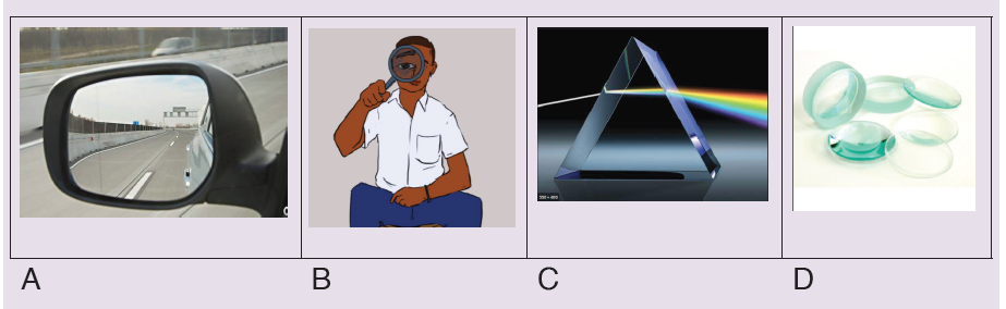
they can be used in our daily life activities
b) What is the effect of light on A, B, C and D?
c) Analyze the phenomenon in figure C thereafter write your
observation in your notebook
d) How the images are formed on the above figures? Explain your
reason
13.1. Types and characteristics of lenses
Activity 13.1
1. Look closely at the lenses and answer these questions in yournotebook:
a) How are the lenses shaped? Explain your answer
b) How are the lenses different?
c) Classify these lenses according to your observation thereafter
explain the conditions used to classify them.
A lens is an optical device with perfect or approximate axial symmetry which
transmits and refractslight, by converging or diverging the beam. Most lenses
are spherical lenses: their two surfaces are parts of the surfaces of spheres.Lenses are classified by the curvature of the two optical surfaces.
A lens is a piece of glass with one or two curved surfaces. The lens which is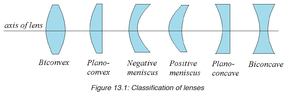
thicker at the centre than at the edges is called a convex lens while the one
which is thinner at its centre is known as a concave lens. The curved surface
of the lens is called a meniscus. The lens in the human eye is thicker in the
centre, and therefore it is a convex lens.
The light rays from the ray box change the direction after passing through the
lens. They are therefore refracted by the lens. Hence, lenses form images of
objects by refracting light.
You can see that the rays from the convex lens are getting closer and closer
to a point. The rays are thus converging, and hence a convex lens is called
a converging lens. You can also see that the refracted rays from the concave
lens are spreading out. This kind of lens is called diverging lens. When light
passes through a lens, refraction occurs at the two lens surfaces.
Using Snell’s law and geometry, you can predict the paths of rays passing
through lenses. To simplify such problems, assume that all refraction occurs
on a plane, called the principal plane that passes through the center of thelens. This approximation, called the thin lens model, applies to all the lenses.
Application activity 13.1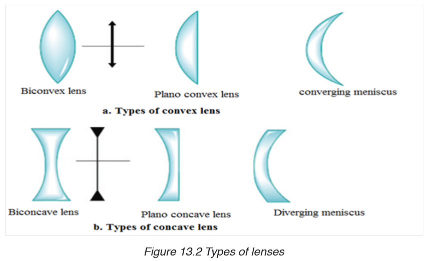
1. The cross sections of four different thin lenses are shown in Figure
below.
a) Which of these lenses, if any, are convex, or converging lenses?
b) Which of these lenses, if any, are concave, or diverging lenses?
c) Why do you make such decision at a and b?d) Where did you see these types of lenses in everyday life?
2. Make a deep research on where this types of lenses are used in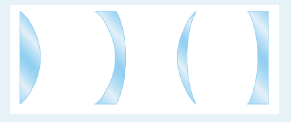
our daily life activities
13.2. Refraction of light through lenses.
Activity 13.2
i. Hold a hand lens about 2 m from the window. Look through the lens.
(CAUTION: Do not look at the sun).
What do you see?
ii. Move the lens farther away from your eye.
What changes do you notice?
iii. Now, hold the lens between the window and a white sheet of paper,
but closer to paper.
iv. Slowly move the lens away from the paper towards the window. Keep
watching the paper.
What do you see? What happens as you move the paper?
Do you see that an inverted image of trees outside is formed on the paper?
How do you think the image is formed?
Lenses can be thought of as a series of tiny refracting prisms, each of
which refracts light to produce an image. These prisms are near each other
(truncated) and when they act together, they produce a bright image focusedat a point.
Each section of a lens acts as a tiny glass prism. The refracting angles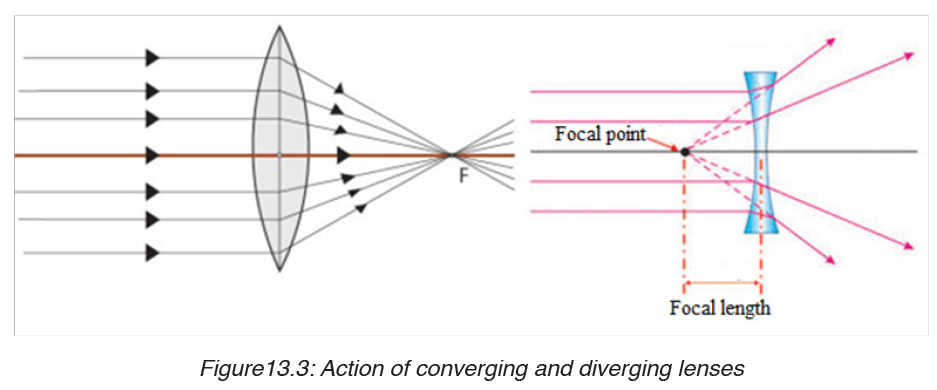
of these prisms decrease from the edges to its centre. As a result, light is
deviated more at the edges than at the centre of the lens.
The refracting angles of the truncated prisms in a converging lens point to
the edges and so bring the parallel rays to a focus.
The truncated prisms of the diverging lens point the opposite way to those of
the converging lens, and so a divergent beam is obtained when parallel rays
are refracted by this lens because the deviation of the light is in the opposite
direction.
The middle part of the lens acts like a rectangular piece of glass and a ray
incident to it strikes it normally, and thus passes without deviation.
13.2.1 Ray diagrams and properties of images formed by lenses
Notice that an image cannot be seen on the screen irrespective of the
position of the object.
The nature of the image formed by a convex lens depends on the position of
the object along the principal axis of the lens.
The principal focus of a lens plays an important part in the formation of
an image by a lens since parallel rays from the object converge to it, and
thus, we consider points F and 2F when describing the nature of the images
formed by the lens.
These images can be larger or smaller than the object or same size as the
object. When an image is larger than the object, we say that it is magnified
and when it is smaller, we say that it is diminished.
Images which can be formed on the screen are Real images. Because light
rays pass through these images, real images can be formed on the screen.
All real images formed by the convex lens are inverted.
To determine an image point, we need to consider only the three rays
indicated if Fig.13.4, which uses an arrow (on the left) as the object, and a
converging lens forming an image to the right. These rays, emanating from
a single point on the object, are drawn as if the lens were infinitely thin, and
we show only a single sharp bend at the centre line of the lens instead ofrefraction at each surface. These three rays are drawn as follows:
The point where these three rays cross is the image point for that object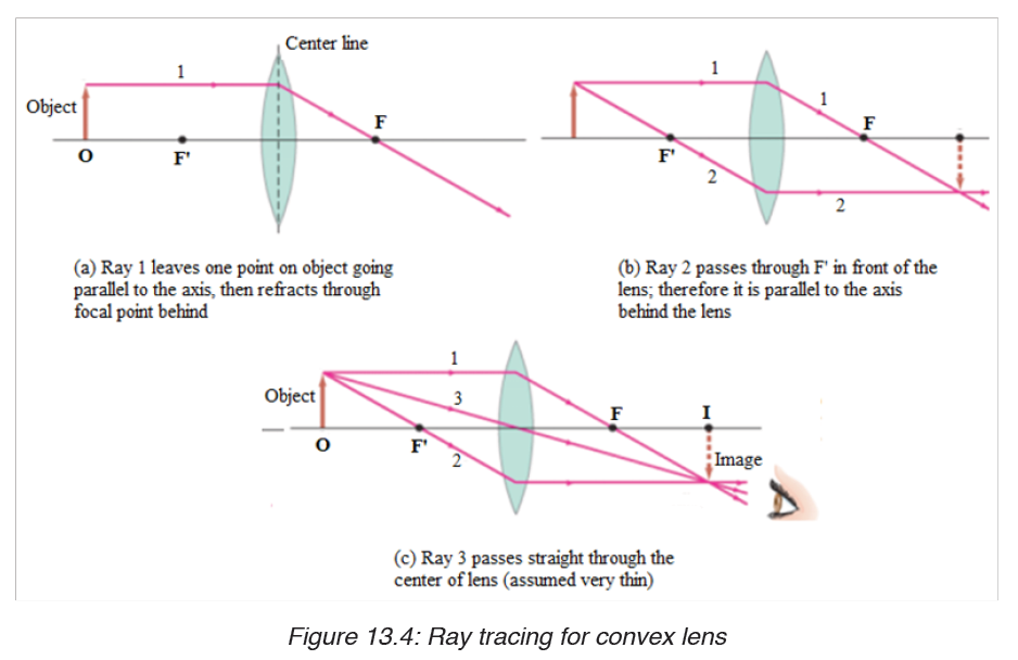
point. Actually, any two of these rays will suffice to locate the image point,
but drawing the third ray can serve as a check.
13.2.2 Graphical construction of images by Converging lens
If the lens is biconvex or plano-convex, a collimated parallel or diverging
beam of light travelling through the lens will be converged to a spot behindthe lens. In this case, the lens is called a converging lens.
When an object is placed at a distance greater than the focal length from the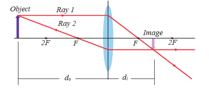
lens, the image is real and inverted on the other side of the lens. When an
object is placed at a distance equal to twice the focal length from the lens,the image is the same size as the object and inverted.
A convex lens forms a virtual image that is upright and larger compared to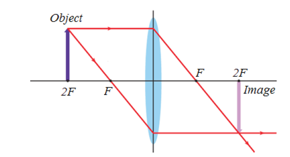
the object when the object is located between the lens and the focal point.
13.2.3 Graphical construction of images by diverging lens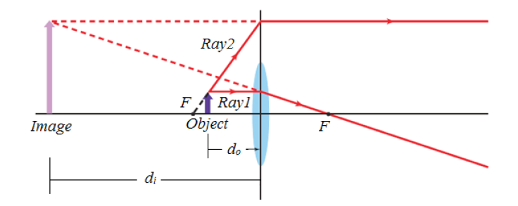
If the lens is biconcave or plano-concave, a beam of light travelling to thelens axis and passing through the lens will be diverged.
Concave lenses produce only virtual images that are upright and smaller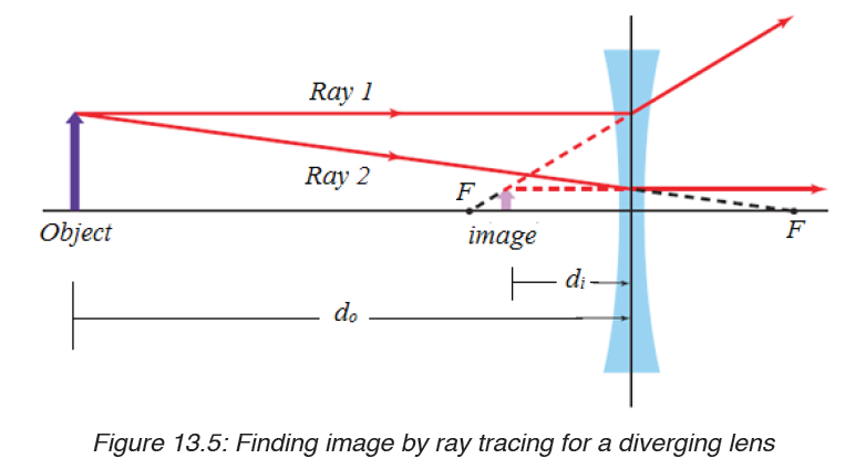
compared to their objects.
When an object is between F and the lens, there is no image formed on
the screen. The image formed is not real and is only seen by removing the
screen and placing an eye in its position. We say that it is a virtual image.
For a virtual image, rays appear to come from its position.
Unlike for a convex lens where the nature of the image depends on the
position of the object, a concave lens gives only an upright, small, virtual
image, and is situated between the principal focus and the lens for allpositions of the object.
Application activity 13.2
1. Design an experiment to study images formed by convex lenses of
various focal lengths. How does the focal length affect the position
and size of the image produced?
2. An object of length 5 cm is placed at a distance 25 cm in front of
a lens of focal length 10 cm.Use a ray diagram to construct the
image of this object and state its properties if the lens is :
a) Converging;
b) Diverging.
13.3. Thin lens equations and determination of focal length
Activity 13.3
Task 1:
i. Place a converging lens on a table while facing a window.
ii. Place a white screen behind the lens. Move the screen to and fro
(forwards and backwards) until a sharp image of a distant object is
seen on the screen.
iii. Discuss and write down the observation in your notebook.
iv. Measure the distance from the lens to the screen. What is thisdistance called?
Task 1:
i. Place a converging lens on a table while facing a window.
ii. Place a white screen behind the lens. Move the screen to and fro
(forwards and backwards) until a sharp image of a distant object is
seen on the screen.
iii. Discuss and write down the observation in your notebook.
iv. Measure the distance from the lens to the screen. What is this
distance called?
Task 2:
i. Draw a ray diagram to determine the nature and position of the image
of an object placed 10cm from a diverging lens of focal length 15cm.
ii. Using the above information, find the nature and position of the
image using a lens formula. (Assign f a negative sign during your
substitution).
iii. What is the location of the image?
13.3.1 Convex lens
We now derive an equation that relates the image distance to the object
distance and focal length of a thin lens. This equation will make the
determination of image position quicker and more accurate than doing ray
tracing. Let be the object distance, the distance of the object from the center
of the lens, and the distance of the image from the center of the lens. And
let and refer to the heights of object and image. Consider two rays shownin Figure below for a converging lens, assumed to be very thin.
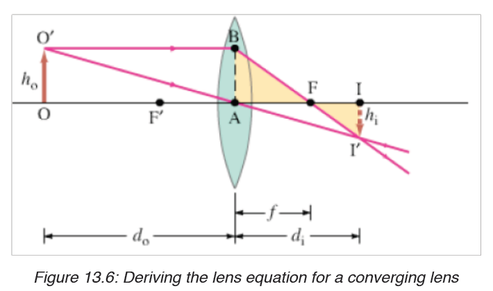
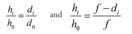
The right triangles FI’I and FBA are similar because angle AFB equals angle IFI’; so
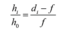
Since length 0 AB = h . Triangles OAO’ and IAI’ are similar as well. Therefore,
We equate the right sides of these equations (the left sides are the same),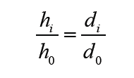
and divide di by to obtain
This is called the thin lens equation. It relates the image distance di to the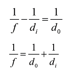
object distance d0 and focal length . It is the most useful equation in geometricoptics. If the object is at infinity, then
length is the image distance for an object at infinity, as mentioned earlier.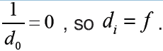 Thus the focal
13.3.2 Concave lensWe can derive the Lens equation for diverging lens using the following figure.
Triangles IAI’ and OAO’ are similar; and triangles IFI’ and AFB are similar.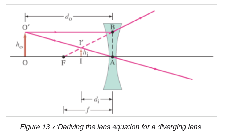
Thus (noting that length AB = h0 )
When we equate the right sides of these two equations and simply, we obtain
This equation becomes the same as that of convex lens if we make f and di negative. That is, we take f to be negative for a diverging lens and di negative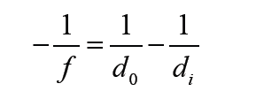
when the image is on the same side of the lens as light comes from.Thus
Will be valid for both converging and diverging lenses, and for all situations,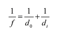
if we use the following sign conventions:
1. The focal length is positive for converging lenses and negative for
diverging lenses.
2. The object distance is positive if the object is on the side of the lens
from which light is coming; otherwise, it is negative.
3. The image distance is positive if the image is on the opposite side
from where light is coming; if it is on the same side, it is negative.
Equivalently, the image distance is positive for real image and
negative for a virtual image.
4. The height of the image, is positive if the image is upright, and
negative if the image is inverted relative to the object. (is always
taken as positive).
13.3.3 Magnification
The magnification, m, of a lens is defined as the ratio of the image heightto object height. From the above figures and the sign conventions, we have
for an upright image the magnification is positive, and for an inverted image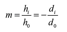
the magnification is negative.
13.3.4 The power of lenses
Whenever a ray of light passes through a lens it bends except when it passes
through the optical centre. The degree of convergence or divergence of a
lens is expressed as power. A lens of short focal length deviates the rays
more while a lens of large focal length deviates the rays less. Thus the power
of a lens is defined as the reciprocal of its focal length.Power of a lens
The unit of power is dioptre (D)1D = 1m−1
From sign convention 1, it follows that the power of converging lens, in
diopters, is positive, whereas the power of a diverging lens is negative. A
converging lens is sometimes referred to as positive lens, and a diverging
lens as a negative lens.In case the lenses are combined
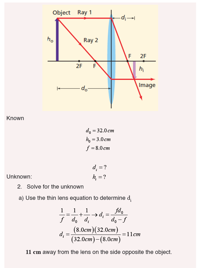
Example 13.3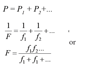
An object is placed 32.0 cm from a convex lens that has a focal length of
8.0 cm.
a) Where is the image?
b) If the object is 3.0 cm high, how tall is the image?
c) What is the orientation of the image?
Solution
1. Analyse and sketch the problem
• Sketch the situation, locating the object and the lens.• Draw the two principal rays
13.3.5 Lens maker formula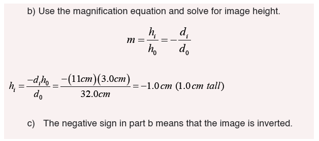
The following assumptions are made for the derivation:
– The lens is thin, so that distances measured from the poles of its
surfaces can be taken as equal to the distances from the optical centre
of the lens.
– The aperture of the lens is small.
– Object point is considered.– Incident and refracted rays make small angles.
Consider a convex lens of absolute refractive index nt to be placed in a rarer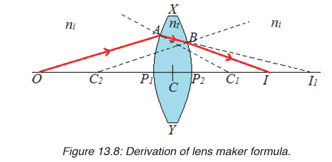
medium of absolute refractive indexni.
Considering the refraction of a point object on the surface XP1Y, the image
is formed at I1 who is at a distance of P1I1.
CI1= P1I1 (as the lens is thin)
CC1 = P1C1=R1
CO = P1O
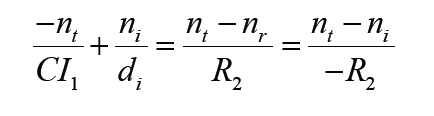
The refracted ray from A suffers a second refraction on the surface XP2Y
and emerges along BI. Therefore Iis the final real image of O. Here the
object distance is
do = CO ≈ CI1 ≈ R1It follows from the refraction due to convex spherical surface XP1Y
Let CI ≈ P2 I = d be the final image distance. Let R2 be radius of curvature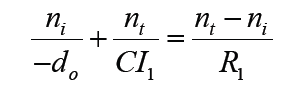
of second surface of the lens.
di = CI ≈ CI1 ≈ R2
It follows from refraction due to concave spherical surface from denser torarer medium that
Adding
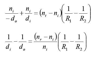
This equation gives the lens maker’s formula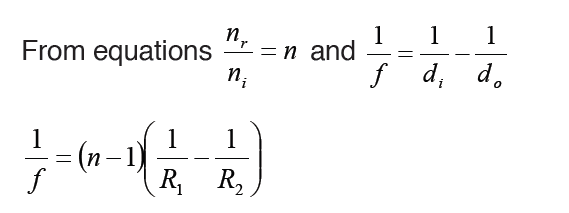
Note:
– The lens maker’s formula indicates that a convex lens can behave like
a diverging one if ni > nt i.e., if the lens is placed in a medium whose
index is greater than the index of lens. Similarly a concave lens can be
made convergent.
– The lens maker’s formula can be derived for a concave lens in the
same way.
Sign convention states that real is positive while virtual is negative. This
should be put under consideration when one is using the lens formula tosolve problems.
Application activity 13.3
1. Compute the composition and focal length of the converging lens
which will project the image lamp, magnified 4 times, upon a screen
10.0 m from the lamp.
2. A lens has a convex surface of radius 20 cm and a concave surface of
radius 40 cm and is made of glass of refractive index 1.54. Compute
the focal length of the lens, and state whether it is a converging or a
diverging lens.
13.4. Defects and correction of lenses
Activity 13.4
i. Place a white sheet of paper on a horizontal ground.
ii. Hold a glass ruler above the paper so as to focus rays from the sun
on to the paper.
iii. Observe carefully the image formed on the sheet of paper.
iv. Repeat the above with the convex lens. What have you observed?
v. Use internet to search for Defects and correction of lenses
Aberration
A lens made of a uniform glass with spherical surface cannot form a perfect
image. The spherical aberration is prominent image defect for a point source
on the optical axis of such a lens. It arises because all rays through the lensare not focused to a common point.
The dependence of index of refraction of wavelength also causes the focal
length, and thereby the image position, to depend on the color of the light.
All simple lenses suffer from such chromatic aberration.
There are several different types of aberration which can cause the image
to be an imperfect replica of the object(Spherical aberration, chromatic
aberration, coma, field curvature, barrel, pincushion distortion, astigmatism,
etc).
Notice that the image has coloured patches. This defect where by an image
formed has coloured patches is called chromatic aberration. There are two
kinds of defects; spherical aberration and chromatic aberration.
13.4.1 Spherical aberration
This arises in lenses of larger aperture when a wide beam of light incident on
the lens, not all rays is brought to one focus.
As a result, the image of the object becomes distorted. The defect is due to
the fact that the focal length of the lens for rays far from the principal axis are
less than for rays closer to a property of a spherical surface and as a result,they converge to a point closer to the lens.
This defect can be minimized (reduced) by surrounding the lens with an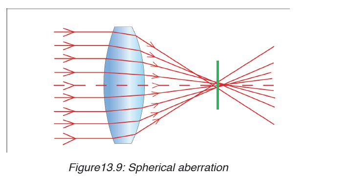
aperture disc having a hole in the middle so that rays fall on the lens at a
point closer to its principal axis. However, this reduces the brightness of the
image since it reduces the amount of light energy passing through the lens.
13.4.2 Chromatic aberration
Chromatic aberration is caused by the dispersion of the lens material. Since,
from the lens formulae, f is dependent upon n, it follows that different coloursof light will be focused to different positions.
Chromatic aberration can be minimised by using an achromatic doublet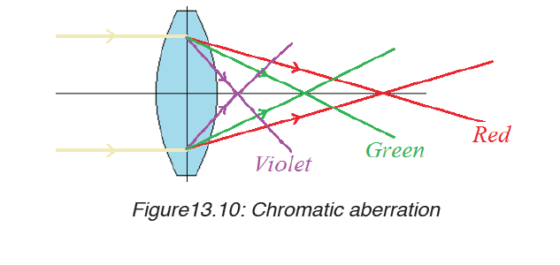
(or achromat) in which two materials with differing dispersion are bondedtogether to form a single lens.
Application activity 13.4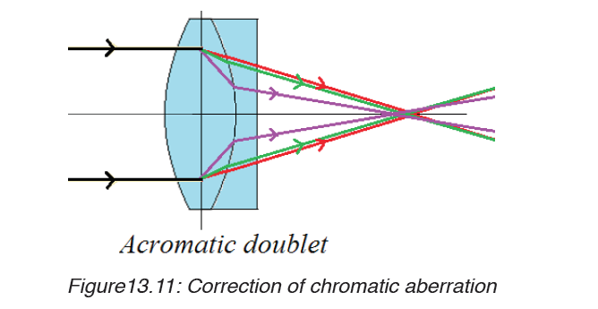
i. How spherical and chromatic aberration can be reduced?
ii. If a plano-convex lens is used as objective lens in a telescope, how
is its convex surface faced to minimize spherical aberration? Explain
13.5. Refraction through prisms
13.5.1. Terms associated with refraction through prism
Activity 13.5
Problem
Have you ever heard of a prism?
How does it look like?
Procedures
a) Consider the shapes of the glasses provided below. Observe them
clearly and identify the shape of a prism.Explain your reasoning.
b) With the help of a teacher, touch, observe and identify the real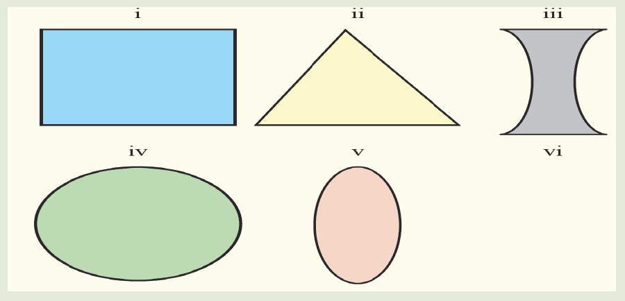
shape of the prism.
c) Examine the features of the one selected as a prism.
In optics, a prism is transparent material like glass or plastic that refracts light.
At least two of the flat surfaces must have an angle less than 90o betweenthem. The exact angle between the surfaces depends on the application
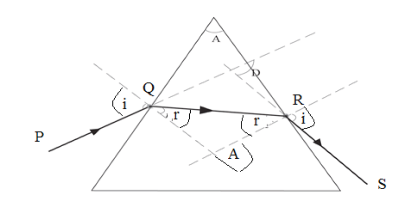
From the figure 13.12, the following terms are used in refraction through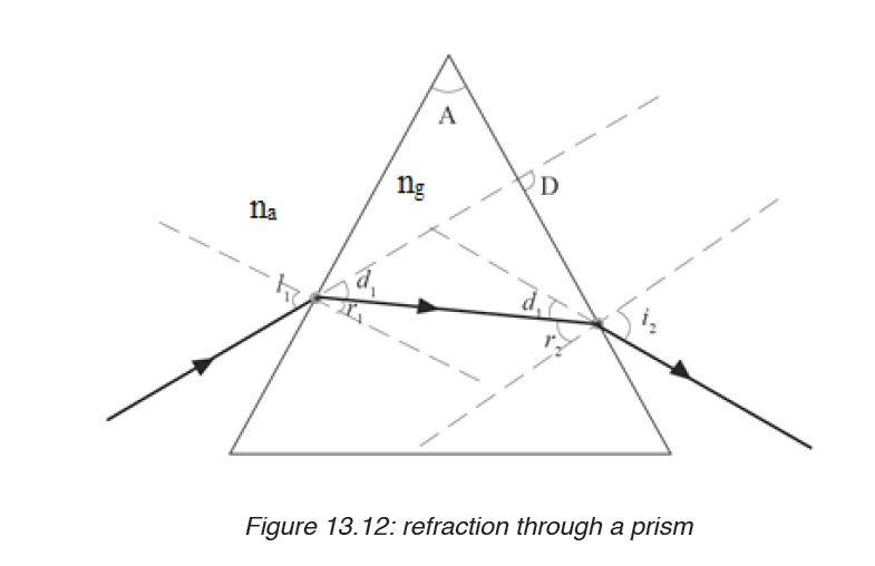
prism.
Angle A: This is called refracting angle or angle of the prism. It is the angle
between the inclined surfaces of the prism.
Angle i: This is the angle of incidence on the first face of the prism.
Angle r1: This is the angle of refraction on the first face of the prism.
Angle r2: This is the angle of refraction on the second face of the prism.
Angle l2: This is the angle of emergence from second face of the prism.
Sometimes this is denoted by letter e.
Angle D: this is the angle of deviation of rays through a prism.
na: is a refractive index in air.
ng:is a refractive index in glass
13.5.2 Dispersion of light by a prism
Dispersion of light is the separation of a beam of light into its constituent
colours. This takes place when a light beam passes through a dispersive
medium. A beam of white light incident on a prism splits into its constituent
colours to form “a visible spectrum”consisted of colours violet, indigo, blue,green, yellow, orange and red.
When a polychromatic light is incident on the first surface of the prism, each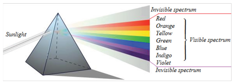
constituent colour gets refracted through a different angle. When these
colours are incident on the second surface of the prism they are again
refracted further.
Application activity 13.5
1. i. Place a prism in the centre of a piece of paper so that its refracting
surface is directly facing the windows in order to receive light from
the sun.
ii. Place a white screen on the far side of the prism so that the
refracted rays hit it.
iii. Observe what is formed on the screen.
iv. In brief, write in your notebook the observation.
2. Do a research to find other terms associated to the refraction light
through prism.
13.6 Deviation by a prism and determination of refractive index
Activity 13.6
1. Have you ever heard of the word deviation? List down in your
notebook at least two ways in which light can be deviated.
2. You are provided with a glass prism of refracting angle 60o, four
optical pins, a white sheet of paper, a soft board and fixing pins.i. Place a prism on a white sheet of paper and mark its outline ABC.
ii. Remove the prism and draw a normal line ON to face AB and draw a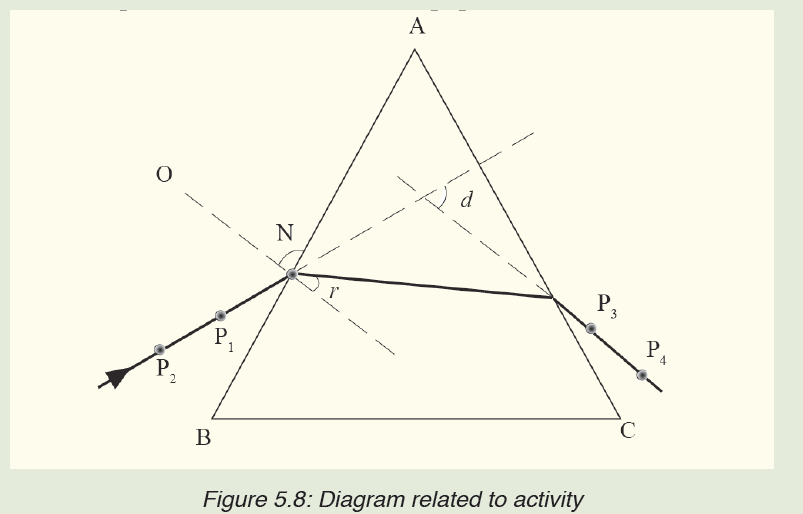
line making an angle of 10o to ON to represent the incident ray.
iii. Place back the prism in its outline and fix pins P1 and P2 along the line.
iv. While looking through the other face AC of the prism, fix pins P3 and
P4 so that they appear in line with images of P1 and P2.
v. Remove the prism and draw a line through P3 and P4 on to face AC
of the prism.
vi. Measure the angle of deviation d.
vii. What is your observation on the direction of incident ray afterrefraction?
In the figure13.13, E F is a ray incident on the refracting surface YX of the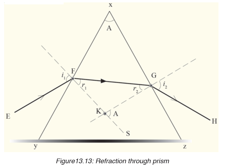
prism XY Z from air and then to air from surface XZ of the prism. KF and KG
are normal at the points of incidence and emergence of the ray respectively.
Now, from the geometry of quadrilateral XFKG,
< X FK + < X GK = 180O and
A + <F K G = 180O ……………………(1)
But since FKS is a straight line,
ΔFKG + ΔGKS = 180O…………….(2)
Comparing equation (1) and (2), it means that, ΔGKS = A.
Using ΔKFG, ΔGKS is an opposite exterior angle of r1 and r2
Thus, r1 + r2 = ΔGKS.
Hence, r1 + r2 = A
Note that given i1, r1 and i2, r2 as angles of incidence and refraction at F and
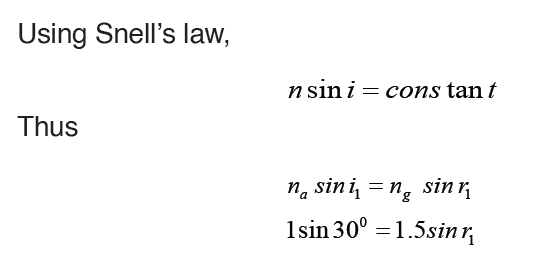
G as shown and n is the prism refractive index, and then Snells law holds.
That is; Sin i1 = n sin r1, and
Sin i2 = n sin r2
The position and shape of the third side of the prism does not affect the
refraction under consideration and so is shown as an irregular in figure.
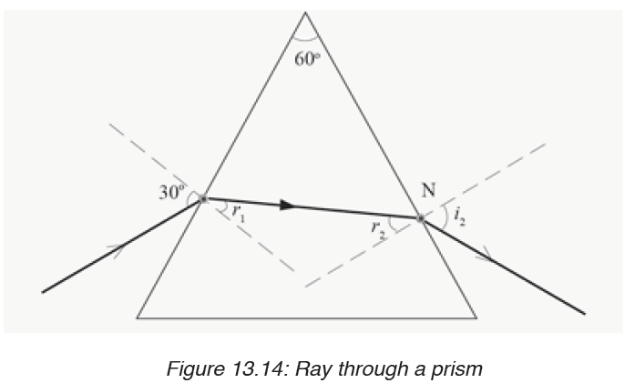
Example
A ray of light falls from air to a prism of refracting angle 60o at an angle of
30o. Calculate the angle of emergence on the second face of the prism (Take
refractive index of the material of glass, ng = 1.5).Solution
1. Deviation of light by a glass prism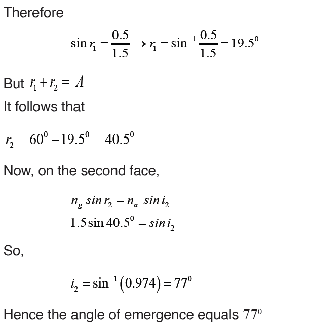
Light can be deviated by reflection and refraction. Since a prism refracts
light, it therefore changes its direction.
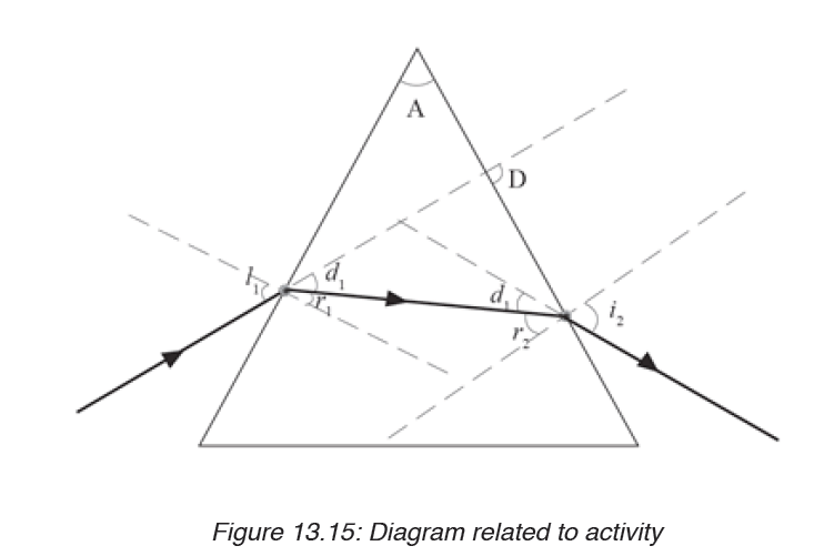
A prism deviates light on both faces. These deviations do not cancel out as in
a parallel sided block where the emergent ray, although displaced, is parallel
to the incident ray surface. The total deviation of a ray due to refraction at
both faces of the prism is the sum of the deviation of the ray due to refractionat the first surface and its deviation at the second face.
N.B: The deviation D for a small angle prism is D = A (n-1)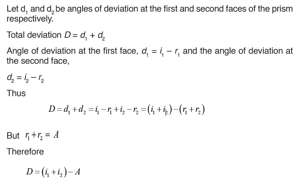
The expression D = A (n – 1) shows that for a given angle A, all rays entering
a small angle prism at small angles of incidence suffer the same deviation.
2. Angle of minimum deviation
From the variation figure below, there is one angle of incidence which gives
a minimum deviation. The experiment shows that this minimum deviation
occurs when the angle of emergence is exactly equal to the angle of incidence
and the two internal angles of refraction are equal.
At this value, a ray passes symmetrically through the prism and the rayinside the prism is perpendicular to the directing plane.
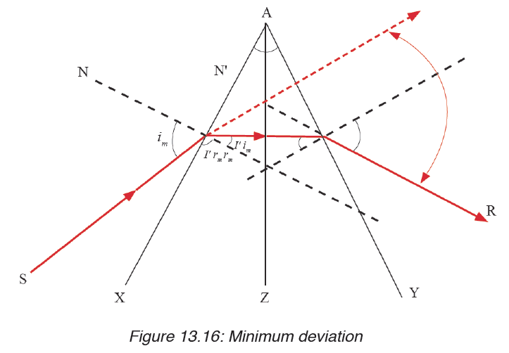
Since the angle of emergence i2 = angle of incidence i1, it follows that
3. Determination of refractive index n of a material of the prism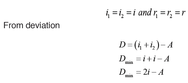
A very convenient formula for refractive index, n, can be obtained in the
minimum deviation case. The ray PQRS then passes symmetrically through
the prism, and the angles made with the normal in the air and in the glass at
Q, R respectively are equal. Suppose the angles are denoted by as shown.Then
Example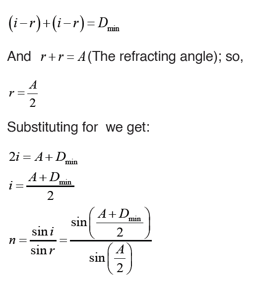
A glass prism of refracting angle 60o has a refractive index of 1.5. Calculate
the angle of minimum deviation for a parallel beam of light passing through it.Solution:
4. Applications of total internal reflection of light by a prism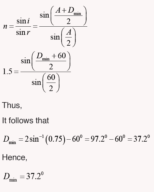
Many optical instruments use right -angled prisms to reflect a beam of light
through 90° or 180° (By total internal reflection) such as cameras, binoculars,periscope and telescope. One of the angles of right angled prism is 90°.
When a ray of light strikes a face of prism perpendicular, it enters the prim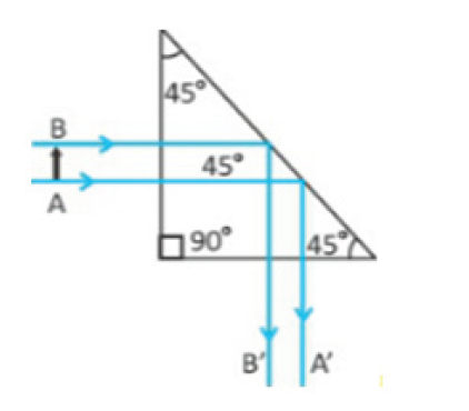
without deviation and strikes the hypotenuse at an angle of 45°. Since the
angle of incidence 45° is greater than critical angle of the glass which is 42°,
the light is totally reflected by the prism through an angle of 90°. Two such
prisms are used in periscope. The light is totally reflected by the prism by an
angle of 180°. Two such prisms are used in binoculars.
Application activity 13.6
1. A ray of light is refracted through a 60 degree prism of ordinary
glass making an incident of 35 degree with the normal i.e incident
ray =35°.What will the angle of emergent ray and the angle of
deviation measure?
2. What are the conditions for minimum deviation when a ray of
light passes through a prism?
3. Find the reflective index of the material of prism, if a thin prism of
angle A is equal to 6 degree, produces a deviation is equal to 3 degree.
4. Show that the deviation produced by a small angled prism is
independent with angle of incidence.
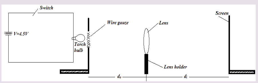
SKILLS LAB 13
DETERMINATION OF THE FOCAL LENGTH OF A LENS
Apparatus required:
1 torch bulb fitted in a bulb holder
1 switch
3 Torch cells
2 Cell holders
Connecting wires about 50cm long.
Wire gauze
Converging lens, of focal length 15cm.
Lens holder,
White screen
Metter rule.
Retort stand with its holding accessories.
Instructions:
In this experiment you will determine the focal length of the converging
lens provided.
a) Mount the on lens the holder and place it facing a window
b) Place the screen behind the lens and adjust the screen until a clear
image of a distant object is obtainedc) Measure and record the distance, x, between the lens and the screen.
End unit assessment 13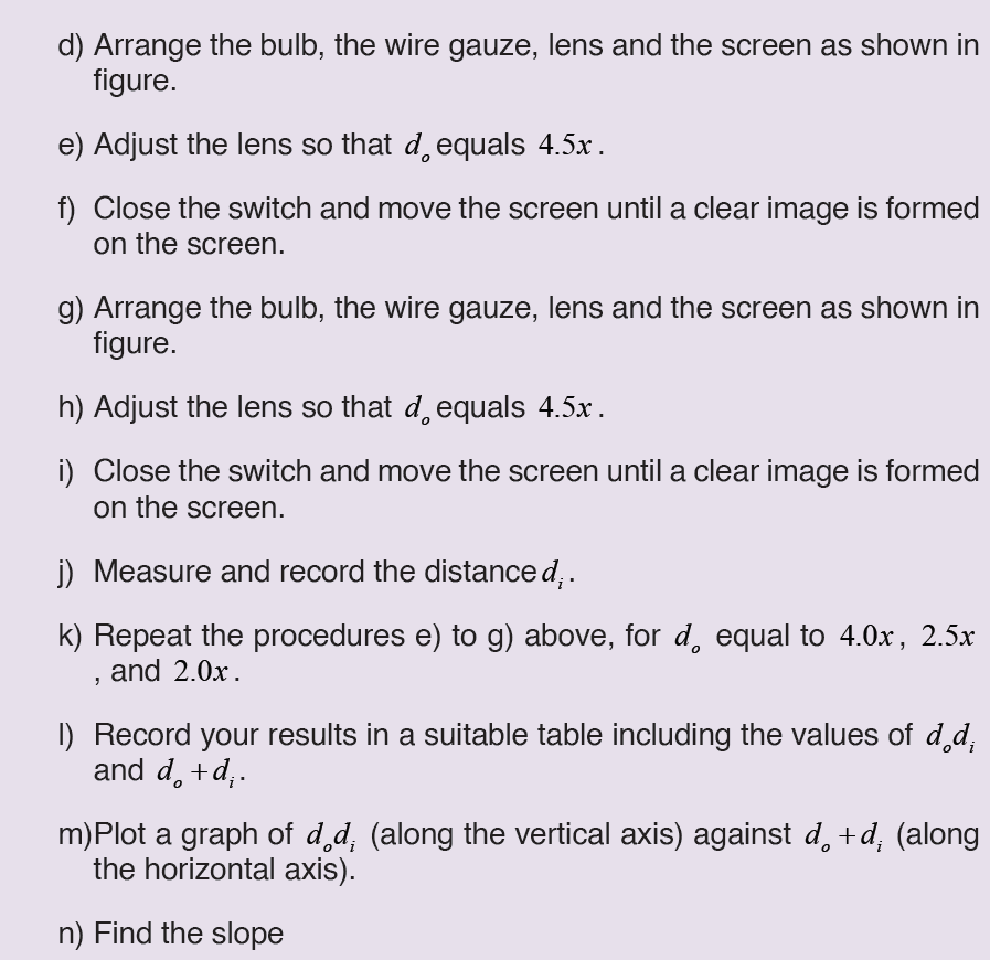
1. Complete the following concept map using the following terms:inverted, larger, smaller, and virtual.
2. Explain the lens defects and their corrections.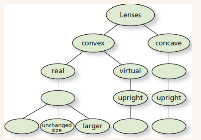
3. A sharp image is located 78.0mm behind a 65.0mm-focal-length
converging lens. Find the object distance (a) using a ray diagram,
(b) by calculation.
4. An object is placed 10cm from a lens of 15m of focal length.
Determine the image position.
5. An object of 2cm is placed at 50 cm from a diverging lens of focal
length 10cm. Determine its image height and location.
6. An object located 32.0 cm in front of a lens forms an image on a
screen 8.00 cm behind the lens.
(a) Find the focal length of the lens.
(b) Determine the magnification.
(c) Is the lens converging or diverging?,(d) Determine the power of this lens.